2007 ISUZU KB P190 catalytic converter
[x] Cancel search: catalytic converterPage 1303 of 6020
Engine Control System (4JH1) 6E-269
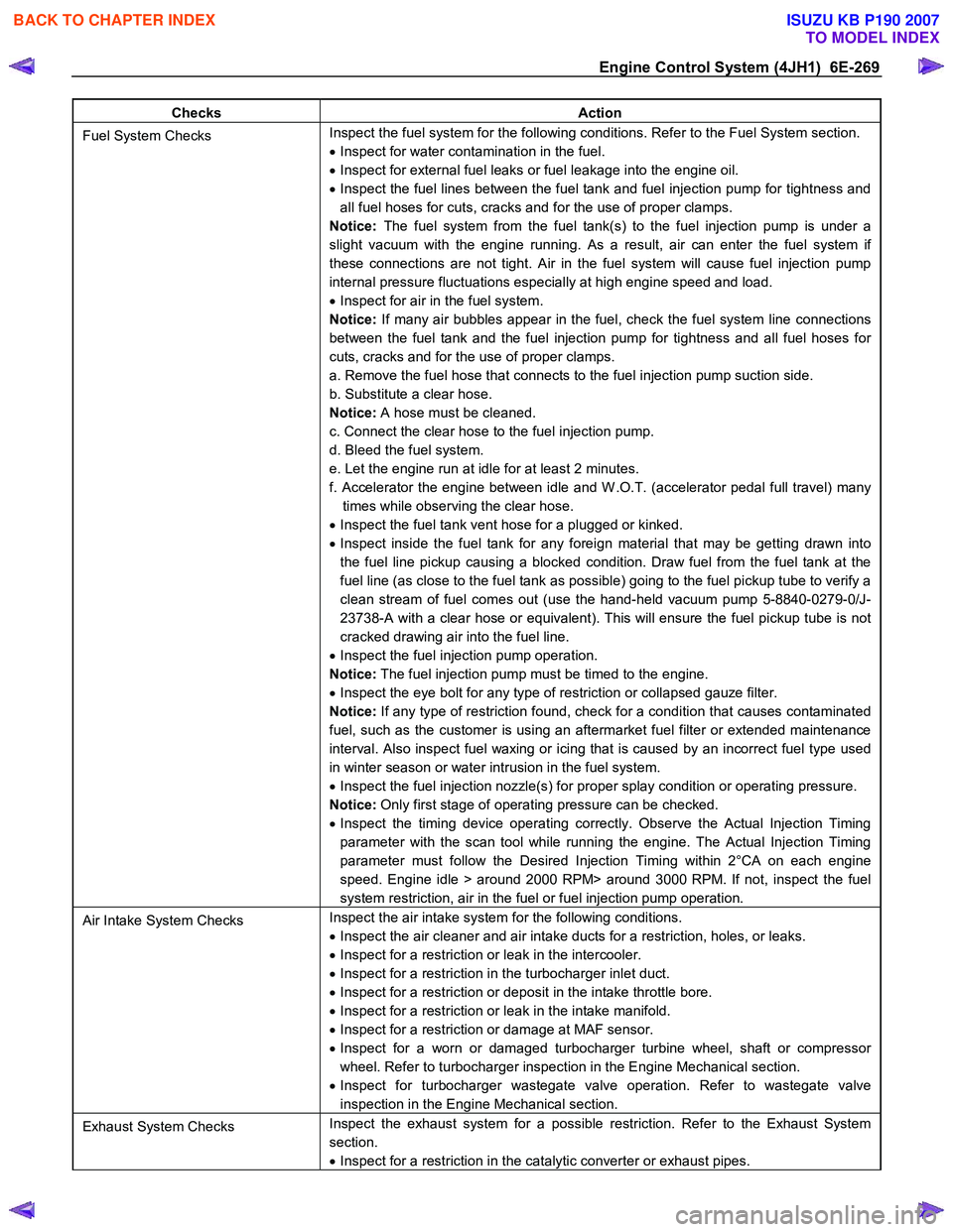
Checks Action
Fuel System Checks Inspect the fuel system for the following conditions. Refer to the Fuel System section.
• Inspect for water contamination in the fuel.
• Inspect for external fuel leaks or fuel leakage into the engine oil.
• Inspect the fuel lines between the fuel tank and fuel injection pump for tightness and
all fuel hoses for cuts, cracks and for the use of proper clamps.
Notice: The fuel system from the fuel tank(s) to the fuel injection pump is under a
slight vacuum with the engine running. As a result, air can enter the fuel system if
these connections are not tight. Air in the fuel system will cause fuel injection pump
internal pressure fluctuations especially at high engine speed and load.
• Inspect for air in the fuel system.
Notice: If many air bubbles appear in the fuel, check the fuel system line connections
between the fuel tank and the fuel injection pump for tightness and all fuel hoses for
cuts, cracks and for the use of proper clamps.
a. Remove the fuel hose that connects to the fuel injection pump suction side.
b. Substitute a clear hose.
Notice: A hose must be cleaned.
c. Connect the clear hose to the fuel injection pump.
d. Bleed the fuel system.
e. Let the engine run at idle for at least 2 minutes.
f. Accelerator the engine between idle and W .O.T. (accelerator pedal full travel) many times while observing the clear hose.
• Inspect the fuel tank vent hose for a plugged or kinked.
• Inspect inside the fuel tank for any foreign material that may be getting drawn into
the fuel line pickup causing a blocked condition. Draw fuel from the fuel tank at the
fuel line (as close to the fuel tank as possible) going to the fuel pickup tube to verify a
clean stream of fuel comes out (use the hand-held vacuum pump 5-8840-0279-0/J-
23738-A with a clear hose or equivalent). This will ensure the fuel pickup tube is not
cracked drawing air into the fuel line.
• Inspect the fuel injection pump operation.
Notice: The fuel injection pump must be timed to the engine.
• Inspect the eye bolt for any type of restriction or collapsed gauze filter.
Notice: If any type of restriction found, check for a condition that causes contaminated
fuel, such as the customer is using an aftermarket fuel filter or extended maintenance
interval. Also inspect fuel waxing or icing that is caused by an incorrect fuel type used
in winter season or water intrusion in the fuel system.
• Inspect the fuel injection nozzle(s) for proper splay condition or operating pressure.
Notice: Only first stage of operating pressure can be checked.
• Inspect the timing device operating correctly. Observe the Actual Injection Timing
parameter with the scan tool while running the engine. The Actual Injection Timing
parameter must follow the Desired Injection Timing within 2°CA on each engine
speed. Engine idle > around 2000 RPM> around 3000 RPM. If not, inspect the fuel
system restriction, air in the fuel or fuel injection pump operation.
Air Intake System Checks Inspect the air intake system for the following conditions.
• Inspect the air cleaner and air intake ducts for a restriction, holes, or leaks.
• Inspect for a restriction or leak in the intercooler.
• Inspect for a restriction in the turbocharger inlet duct.
• Inspect for a restriction or deposit in the intake throttle bore.
• Inspect for a restriction or leak in the intake manifold.
• Inspect for a restriction or damage at MAF sensor.
• Inspect for a worn or damaged turbocharger turbine wheel, shaft or compressor
wheel. Refer to turbocharger inspection in the Engine Mechanical section.
• Inspect for turbocharger wastegate valve operation. Refer to wastegate valve
inspection in the Engine Mechanical section.
Exhaust System Checks Inspect the exhaust system for a possible restriction. Refer to the Exhaust System
section.
• Inspect for a restriction in the catalytic converter or exhaust pipes.
BACK TO CHAPTER INDEX
TO MODEL INDEX
ISUZU KB P190 2007
Page 1306 of 6020
6E-272 Engine Control System (4JH1)
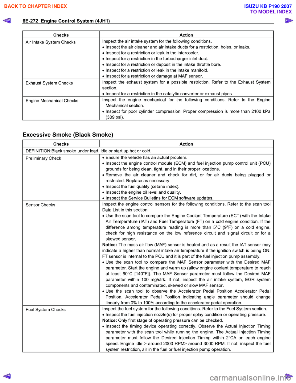
Checks Action
Air Intake System Checks Inspect the air intake system for the following conditions.
• Inspect the air cleaner and air intake ducts for a restriction, holes, or leaks.
• Inspect for a restriction or leak in the intercooler.
• Inspect for a restriction in the turbocharger inlet duct.
• Inspect for a restriction or deposit in the intake throttle bore.
• Inspect for a restriction or leak in the intake manifold.
• Inspect for a restriction or damage at MAF sensor.
Exhaust System Checks Inspect the exhaust system for a possible restriction. Refer to the Exhaust System
section.
• Inspect for a restriction in the catalytic converter or exhaust pipes.
Engine Mechanical Checks Inspect the engine mechanical for the following conditions. Refer to the Engine
Mechanical section.
• Inspect for poor cylinder compression. Proper compression is more than 2100 kPa
(309 psi).
Excessive Smoke (Black Smoke)
Checks Action
DEFINITION:Black smoke under load, idle or start up hot or cold.
Preliminary Check •
Ensure the vehicle has an actual problem.
• Inspect the engine control module (ECM) and fuel injection pump control unit (PCU)
grounds for being clean, tight, and in their proper locations.
• Remove the air cleaner and check for dirt, or for air ducts being plugged or
restricted. Replace as necessary.
• Inspect the fuel quality (cetane index).
• Inspect the engine oil level and quality.
• Inspect the Service Bulletins for ECM software updates.
Sensor Checks Inspect the engine control sensors for the following conditions. Refer to the scan tool
Data List in this section.
• Use the scan tool to compare the Engine Coolant Temperature (ECT) with the Intake
Air Temperature (IAT) and Fuel Temperature (FT) on a cold engine condition. If the
difference among temperature reading is more than 5°C (9°F) on a cold engine,
check for high resistance on the low reference circuit and signal circuit or for a
skewed sensor.
Notice: The mass air flow (MAF) sensor is heated and as a result the IAT sensor may
indicate a higher than normal intake air temperature if the ignition switch is being ON.
FT sensor is internal to the PCU and it is part of the fuel injection pump assembly.
• Use the scan tool to compare the MAF Sensor parameter with the Desired MAF
parameter. Start the engine and warm up (allow engine coolant temperature to reach
at least 60°C [140°F]). The MAF Sensor parameter must follow the Desired MAF
parameter within 100 mg/strk. If not, inspect the air intake system, EGR system
components and contaminated, skewed or slow MAF sensor.
• Use the scan tool to observe the Accelerator Pedal Position Accelerator Pedal
Position. Accelerator Pedal Position indicating angle parameter should change
linearly from 0% to 100% according to the accelerator pedal operation.
Fuel System Checks Inspect the fuel system for the following conditions. Refer to the Fuel System section.
• Inspect the fuel injection nozzle(s) for proper splay condition or operating pressure.
Notice: Only first stage of operating pressure can be checked.
• Inspect the timing device operating correctly. Observe the Actual Injection Timing
parameter with the scan tool while running the engine. The Actual Injection Timing
parameter must follow the Desired Injection Timing within 2°CA on each engine
speed. Engine idle > around 2000 RPM> around 3000 RPM. If not, inspect the fuel
system restriction, air in the fuel or fuel injection pump operation.
BACK TO CHAPTER INDEX
TO MODEL INDEX
ISUZU KB P190 2007
Page 1307 of 6020
Engine Control System (4JH1) 6E-273
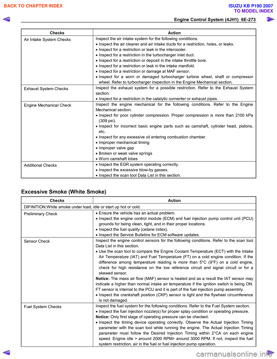
Checks Action
Air Intake System Checks Inspect the air intake system for the following conditions.
• Inspect the air cleaner and air intake ducts for a restriction, holes, or leaks.
• Inspect for a restriction or leak in the intercooler.
• Inspect for a restriction in the turbocharger inlet duct.
• Inspect for a restriction or deposit in the intake throttle bore.
• Inspect for a restriction or leak in the intake manifold.
• Inspect for a restriction or damage at MAF sensor.
• Inspect for a worn or damaged turbocharger turbine wheel, shaft or compressor
wheel. Refer to turbocharger inspection in the Engine Mechanical section.
Exhaust System Checks Inspect the exhaust system for a possible restriction. Refer to the Exhaust System
section.
• Inspect for a restriction in the catalytic converter or exhaust pipes.
Engine Mechanical Check Inspect the engine mechanical for the following conditions. Refer to the Engine
Mechanical section.
• Inspect for poor cylinder compression. Proper compression is more than 2100 kPa
(309 psi).
• Inspect for incorrect basic engine parts such as camshaft, cylinder head, pistons,
etc.
• Inspect for any excessive oil entering combustion chamber.
• Improper mechanical timing
• Improper valve gap
• Broken or weak valve springs
• W orn camshaft lobes
Additional Checks •
Inspect the EGR system operating correctly.
• Inspect the excessive blow-by gasses.
• Inspect the scan tool Data List in this section.
Excessive Smoke (White Smoke)
Checks Action
DIFINITION:W hite smoke under load, idle or start up hot or cold.
Preliminary Check •
Ensure the vehicle has an actual problem.
• Inspect the engine control module (ECM) and fuel injection pump control unit (PCU)
grounds for being clean, tight, and in their proper locations.
• Inspect the fuel quality (cetane index).
• Inspect the Service Bulletins for ECM software updates.
Sensor Check Inspect the engine control sensors for the following conditions. Refer to the scan tool
Data List in this section.
• Use the scan tool to compare the Engine Coolant Temperature (ECT) with the Intake
Air Temperature (IAT) and Fuel Temperature (FT) on a cold engine condition. If the
difference among temperature reading is more than 5°C (9°F) on a cold engine,
check for high resistance on the low reference circuit and signal circuit or for a
skewed sensor.
Notice: The mass air flow (MAF) sensor is heated and as a result the IAT sensor may
indicate a higher than normal intake air temperature if the ignition switch is being ON.
FT sensor is internal to the PCU and it is part of the fuel injection pump assembly.
• Inspect the crankshaft position (CKP) sensor is tight and the flywheel circumference
is not damaged.
Fuel System Checks Inspect the fuel system for the following conditions. Refer to the Fuel System section.
• Inspect the fuel injection nozzle(s) for proper splay condition or operating pressure.
Notice: Only first stage of operating pressure can be checked.
• Inspect the timing device operating correctly. Observe the Actual Injection Timing
parameter with the scan tool while running the engine. The Actual Injection Timing
parameter must follow the Desired Injection Timing within 2°CA on each engine
speed. Engine idle > around 2000 RPM> around 3000 RPM. If not, inspect the fuel
system restriction, air in the fuel or fuel injection pump operation.
BACK TO CHAPTER INDEX
TO MODEL INDEX
ISUZU KB P190 2007
Page 1338 of 6020
EXHAUST SYSTEM 6F – 5
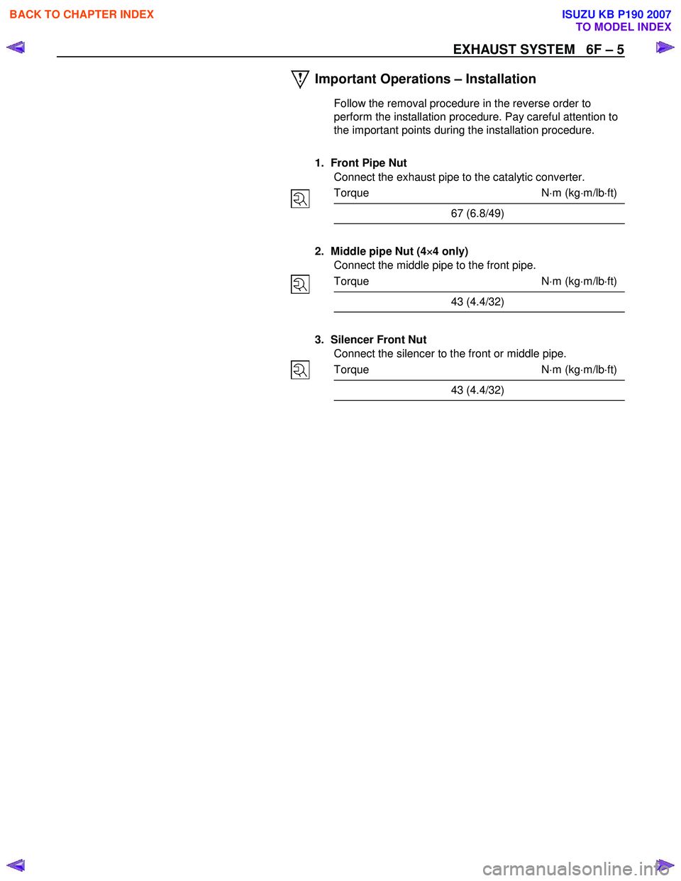
Important Operations – Installation
Follow the removal procedure in the reverse order to
perform the installation procedure. Pay careful attention to
the important points during the installation procedure.
1. Front Pipe Nut Connect the exhaust pipe to the catalytic converter.
Torque N ⋅m (kg ⋅m/lb ⋅ft)
67 (6.8/49)
2. Middle pipe Nut (4 ×
××
×
4 only)
Connect the middle pipe to the front pipe.
Torque N ⋅m (kg ⋅m/lb ⋅ft)
43 (4.4/32)
3. Silencer Front Nut Connect the silencer to the front or middle pipe.
Torque N ⋅m (kg ⋅m/lb ⋅ft)
43 (4.4/32)
BACK TO CHAPTER INDEX
TO MODEL INDEX
ISUZU KB P190 2007
Page 1339 of 6020
6F – 6 EXHAUST SYSTEM
INSPECTION AND REPAIR
Make the necessary adjustments, repairs, and part replacements if excessive wear or damage is discovered during
inspection.
Front Exhaust Pipe
Exhaust Silencer
Check the pipes for corrosion, cracking, damage or
misalignment and repair as required.
Check the rubber rings for deterioration or damage and repair
as required.
Catalytic Converter
1. Inspect outside the catalytic converter for any hitting mark.
2. Visual check inside the catalytic converter for crack or break converter element.
3. If find any problem during the inspection, replace the catalytic converter assembly.
BACK TO CHAPTER INDEX
TO MODEL INDEX
ISUZU KB P190 2007
Page 1377 of 6020
ENGINE MECHANICAL (4JK1/4JJ1) 6A-17
RTW 56ASH004401
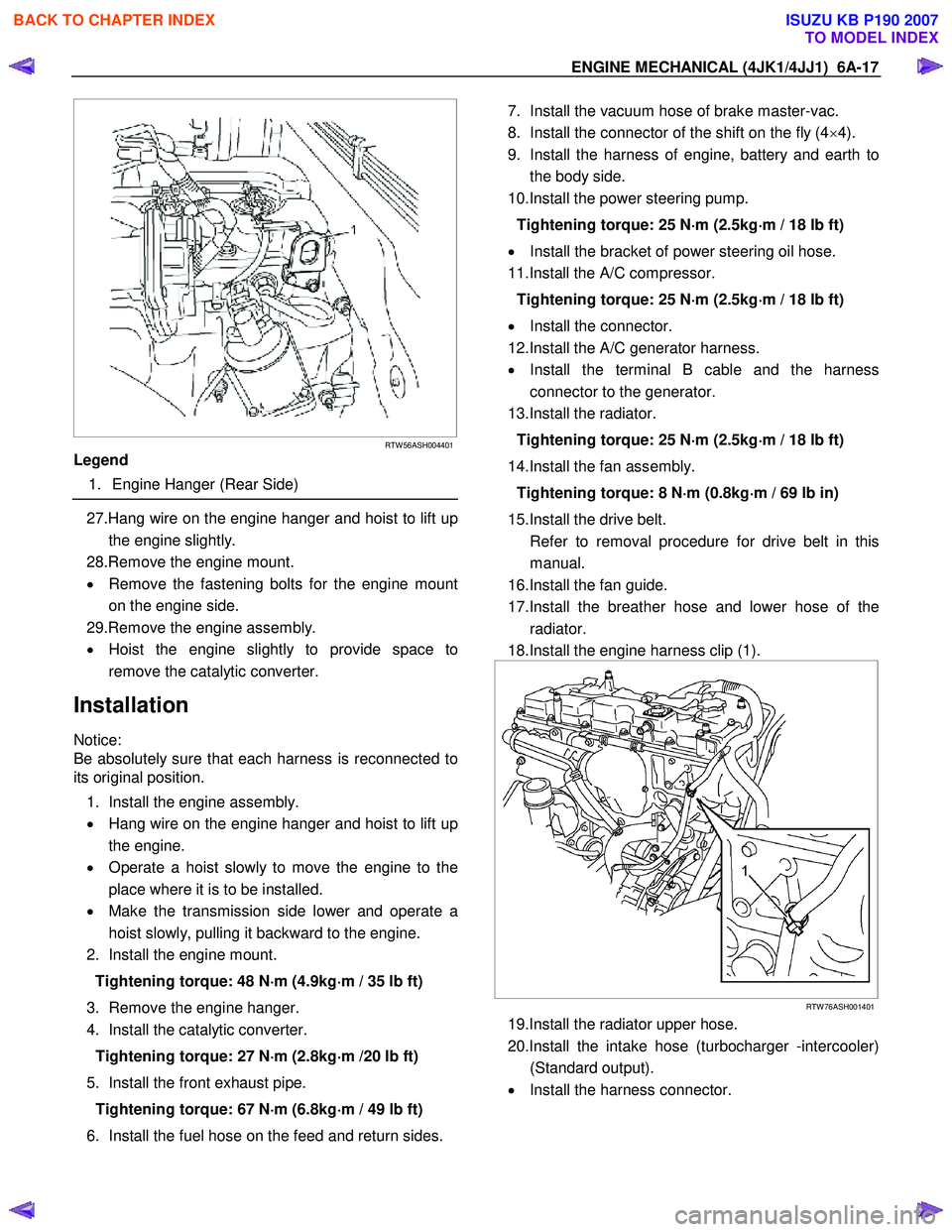
Legend
1. Engine Hanger (Rear Side)
27.Hang wire on the engine hanger and hoist to lift up
the engine slightly.
28.Remove the engine mount.
• Remove the fastening bolts for the engine mount
on the engine side.
29.Remove the engine assembly.
• Hoist the engine slightly to provide space to
remove the catalytic converter.
Installation
Notice:
Be absolutely sure that each harness is reconnected to
its original position.
1. Install the engine assembly.
• Hang wire on the engine hanger and hoist to lift up
the engine.
• Operate a hoist slowly to move the engine to the
place where it is to be installed.
• Make the transmission side lower and operate a
hoist slowly, pulling it backward to the engine.
2. Install the engine mount.
Tightening torque: 48 N ⋅
⋅⋅
⋅
m (4.9kg ⋅
⋅⋅
⋅
m / 35 lb ft)
3. Remove the engine hanger.
4. Install the catalytic converter.
Tightening torque: 27 N ⋅
⋅⋅
⋅
m (2.8kg ⋅
⋅⋅
⋅
m /20 lb ft)
5. Install the front exhaust pipe. Tightening torque: 67 N ⋅
⋅⋅
⋅
m (6.8kg ⋅
⋅⋅
⋅
m / 49 lb ft)
6. Install the fuel hose on the feed and return sides.
7. Install the vacuum hose of brake master-vac.
8. Install the connector of the shift on the fly (4 ×4).
9. Install the harness of engine, battery and earth to the body side.
10.Install the power steering pump.
Tightening torque: 25 N ⋅
⋅⋅
⋅
m (2.5kg ⋅
⋅⋅
⋅
m / 18 lb ft)
• Install the bracket of power steering oil hose.
11.Install the A/C compressor.
Tightening torque: 25 N ⋅
⋅⋅
⋅
m (2.5kg ⋅
⋅⋅
⋅
m / 18 lb ft)
• Install the connector.
12.Install the A/C generator harness.
• Install the terminal B cable and the harness
connector to the generator.
13.Install the radiator.
Tightening torque: 25 N ⋅
⋅⋅
⋅
m (2.5kg ⋅
⋅⋅
⋅
m / 18 lb ft)
14.Install the fan assembly. Tightening torque: 8 N ⋅
⋅⋅
⋅
m (0.8kg ⋅
⋅⋅
⋅
m / 69 lb in)
15.Install the drive belt.
Refer to removal procedure for drive belt in this manual.
16.Install the fan guide.
17.Install the breather hose and lower hose of the radiator.
18.Install the engine harness clip (1).
RTW 76ASH001401
19.Install the radiator upper hose.
20.Install the intake hose (turbocharger -intercooler) (Standard output).
• Install the harness connector.
BACK TO CHAPTER INDEX
TO MODEL INDEX
ISUZU KB P190 2007
Page 1989 of 6020
6F-4 EXHAUST SYSTEM (4JK1/4JJ1)
Removal
1. Rear hanger rubber
2. Silencer front nut
3. Exhaust silencer
4. Silencer hanger rubber
5. Front hanger rubber
6. Middle pipe nut (4 ×2 High Ride Suspension, 4 ×4)
7. Middle pipe (4 ×2 High Ride Suspension, 4 ×4)
8. Front pipe nut
9. Exhaust pipe gasket
Installation
Follow the removal procedure in the reverse order to
perform the installation procedure. Pay careful attention
to the important points during the installation procedure.
1. Front Pipe Nut
Connect the exhaust pipe to the catalytic converter.
Torque: 67 N ⋅
⋅⋅
⋅
m (6.8 kg ⋅
⋅⋅
⋅
m / 49 lb ft)
2. Middle pipe Nut (4 ×2 High Ride Suspension,4 ×4)
Connect the middle pipe to the front pipe.
Torque: 43 N ⋅
⋅⋅
⋅
m (4.4 kg ⋅
⋅⋅
⋅
m / 32 lb ft)
3. Silencer Front Nut
Connect the silencer to the front or middle pipe.
Torque: 43 N ⋅
⋅⋅
⋅
m (4.4 kg ⋅
⋅⋅
⋅
m / 32 lb ft)
BACK TO CHAPTER INDEX
TO MODEL INDEX
ISUZU KB P190 2007
Page 2092 of 6020
6A-78 ENGINE MECHANICAL (C24SE)
Cooling System
Radiator
Type: Cross-flow
Radiator core surface in cm
2: 2000
Cooling system capacity (in litres): 8
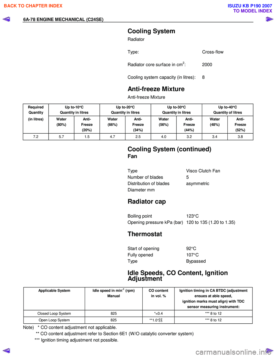
Anti-freeze Mixture
Anti-freeze Mixture
Required
Quantity Up to-10
°
°°
°
C
Quantity in litres Up to-20
°
°°
°
C
Quantity in litres Up to-30
°
°°
°
C
Quantity in litres Up to-40
°
°°
°
C
Quantity of litres
(in litres) Water (80%) An ti -
Freeze (20%) Water
(66%) An ti -
Freeze (34%) Water
(56%) An ti -
Freeze (44%) Water
(48%) An ti -
Freeze (52%)
7.2 5.7 1.5 4.7 2.5 4.0 3.2 3.4 3.8
Cooling System (continued)
Fan
Type Visco Clutch Fan
Number of blades 5
Distribution of blades asymmetric
Diameter mm
Radiator cap
Boiling point 123°C
Opening pressure kPa (bar) 120 to 135 (1.20 to 1.35)
Thermostat
Start of opening 92°C
Fully opened 107°C
Type Bypassed
Idle Speeds, CO Content, Ignition
Adjustment
Applicable System Idle speed in min-1 (rpm)
Manual CO content
in vol. % Ignition timing in CA BTDC (adjustment
ensues at able speed,
ignition marks must align) with TDC sensor measuring instrument:
Closed Loop System 825 *<0.4 *** 8 to 12
Open Loop System 825
**1.0+0.2
-0.5 *** 8 to 12
Note) * CO content adjustment not applicable.
** CO content adjustment refer to Section 6E1 (W /O catalytic converter system)
*** Ignition timing adjustment not possible.
BACK TO CHAPTER INDEX
TO MODEL INDEX
ISUZU KB P190 2007