2007 ISUZU KB P190 catalytic converter
[x] Cancel search: catalytic converterPage 2459 of 6020
6F-10 ENGINE EXHAUST
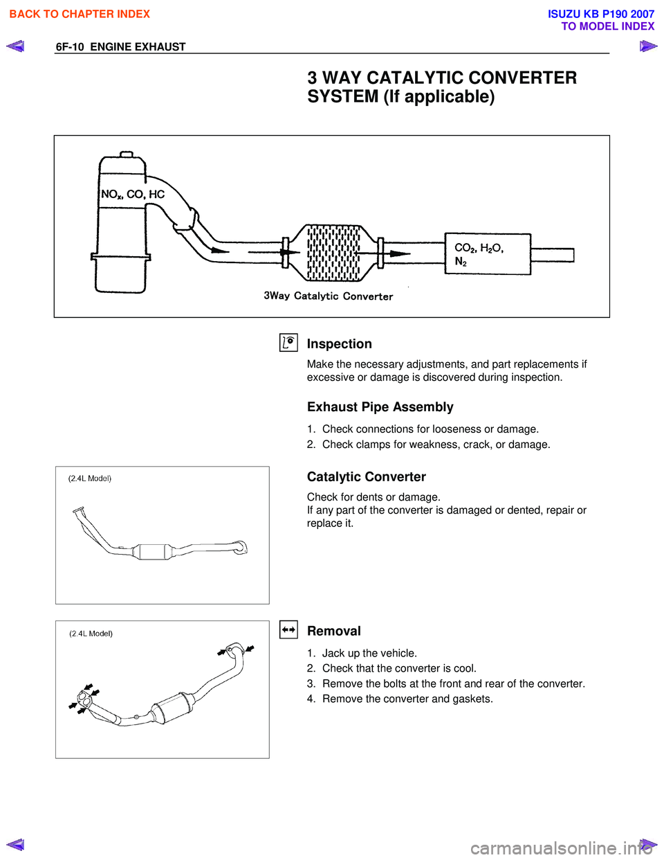
3 WAY CATALYTIC CONVERTER
SYSTEM (If applicable)
N2
Inspection
Make the necessary adjustments, and part replacements if
excessive or damage is discovered during inspection.
Exhaust Pipe Assembly
1. Check connections for looseness or damage.
2. Check clamps for weakness, crack, or damage.
Catalytic Converter
Check for dents or damage.
If any part of the converter is damaged or dented, repair or
replace it.
Removal
1. Jack up the vehicle.
2. Check that the converter is cool.
3. Remove the bolts at the front and rear of the converter.
4. Remove the converter and gaskets.
BACK TO CHAPTER INDEX
TO MODEL INDEX
ISUZU KB P190 2007
Page 2463 of 6020
6F-14 ENGINE EXHAUST
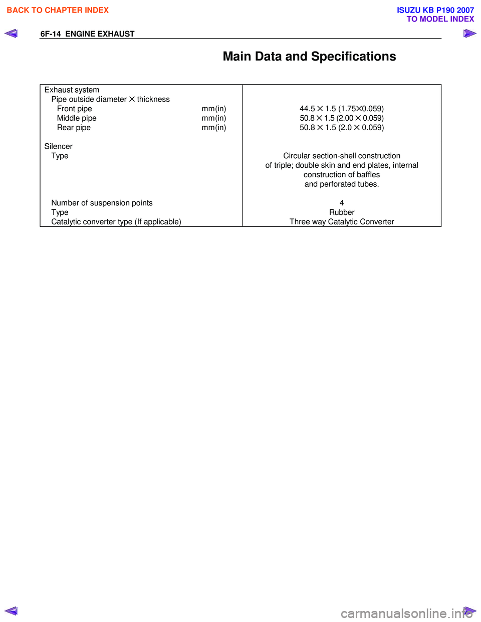
Main Data and Specifications
Exhaust system
Pipe outside diameter ✕ thickness
Front pipe mm(in) 44.5 ✕ 1.5 (1.75 ✕0.059)
Middle pipe mm(in) 50.8 ✕ 1.5 (2.00 ✕ 0.059)
Rear pipe mm(in) 50.8 ✕ 1.5 (2.0 ✕ 0.059)
Silencer
Type Circular section-shell construction
of triple; double skin and end plates, internal construction of baffles and perforated tubes.
Number of suspension points
Type
Catalytic converter type (If applicable) 4
Rubber
Three way Catalytic Converter
BACK TO CHAPTER INDEX
TO MODEL INDEX
ISUZU KB P190 2007
Page 2508 of 6020
Engine Mechanical – V6 Page 6A1–29
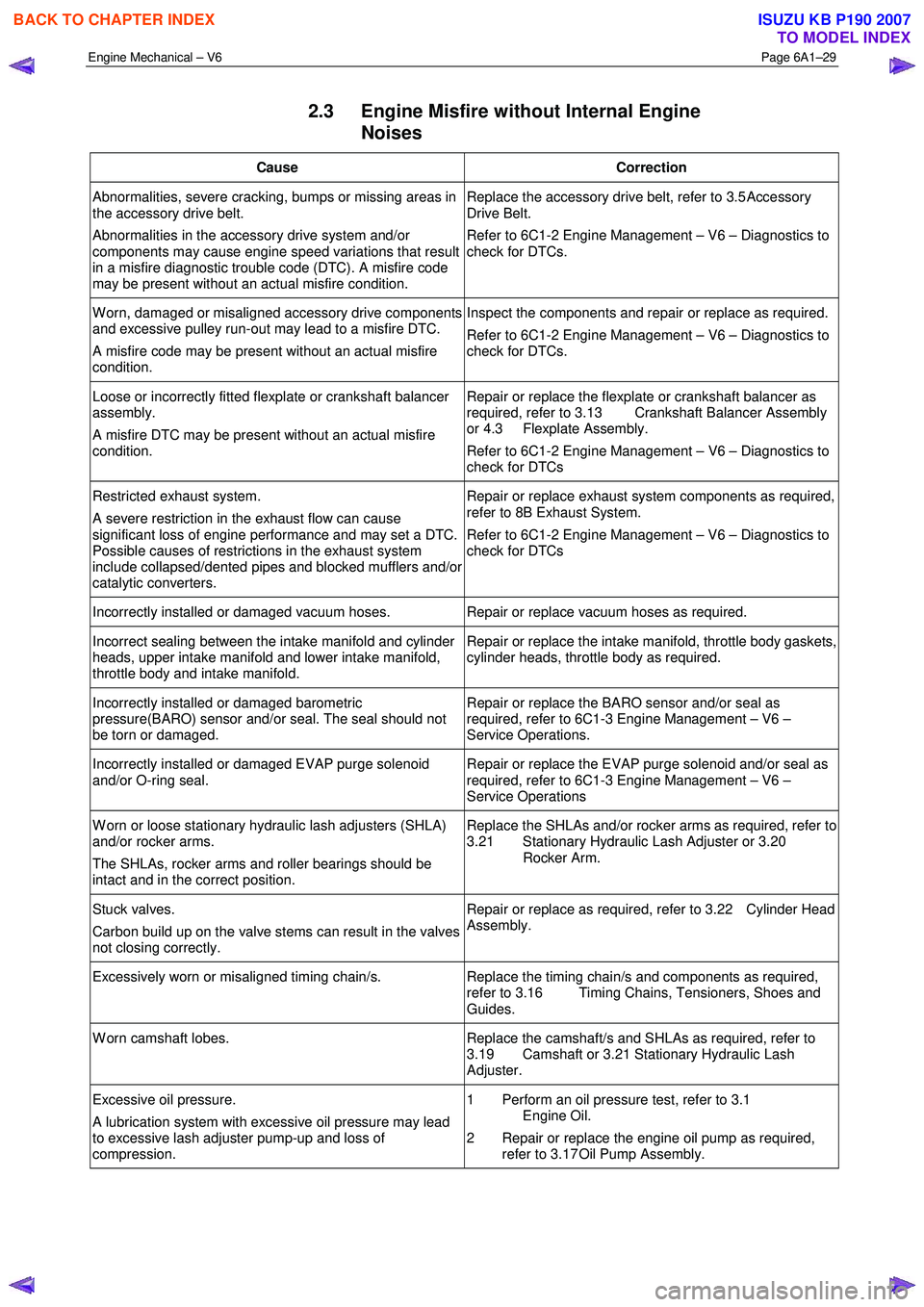
2.3 Engine Misfire without Internal Engine
Noises
Cause Correction
Abnormalities, severe cracking, bumps or missing areas in
the accessory drive belt.
Abnormalities in the accessory drive system and/or
components may cause engine speed variations that result
in a misfire diagnostic trouble code (DTC). A misfire code
may be present without an actual misfire condition. Replace the accessory drive belt, refer to 3.5
Accessory
Drive Belt.
Refer to 6C1-2 Engine Management – V6 – Diagnostics to
check for DTCs.
W orn, damaged or misaligned accessory drive components
and excessive pulley run-out may lead to a misfire DTC.
A misfire code may be present without an actual misfire
condition. Inspect the components and repair or replace as required.
Refer to 6C1-2 Engine Management – V6 – Diagnostics to
check for DTCs.
Loose or incorrectly fitted flexplate or crankshaft balancer
assembly.
A misfire DTC may be present without an actual misfire
condition. Repair or replace the flexplate or crankshaft balancer as
required, refer to 3.13 Crankshaft Balancer Assembly
or 4.3 Flexplate Assembly.
Refer to 6C1-2 Engine Management – V6 – Diagnostics to
check for DTCs
Restricted exhaust system.
A severe restriction in the exhaust flow can cause
significant loss of engine performance and may set a DTC.
Possible causes of restrictions in the exhaust system
include collapsed/dented pipes and blocked mufflers and/or
catalytic converters. Repair or replace exhaust system components as required,
refer to 8B Exhaust System.
Refer to 6C1-2 Engine Management – V6 – Diagnostics to
check for DTCs
Incorrectly installed or damaged vacuum hoses. Repair or replace vacuum hoses as required.
Incorrect sealing between the intake manifold and cylinder
heads, upper intake manifold and lower intake manifold,
throttle body and intake manifold. Repair or replace the intake manifold, throttle body gaskets,
cylinder heads, throttle body as required.
Incorrectly installed or damaged barometric
pressure(BARO) sensor and/or seal. The seal should not
be torn or damaged. Repair or replace the BARO sensor and/or seal as
required, refer to 6C1-3 Engine Management – V6 –
Service Operations.
Incorrectly installed or damaged EVAP purge solenoid
and/or O-ring seal. Repair or replace the EVAP purge solenoid and/or seal as
required, refer to 6C1-3 Engine Management – V6 –
Service Operations
W orn or loose stationary hydraulic lash adjusters (SHLA)
and/or rocker arms.
The SHLAs, rocker arms and roller bearings should be
intact and in the correct position. Replace the SHLAs and/or rocker arms as required, refer to
3.21 Stationary Hydraulic Lash Adjuster or 3.20
Rocker Arm.
Stuck valves.
Carbon build up on the valve stems can result in the valves
not closing correctly. Repair or replace as required, refer to 3.22 Cylinder Head
Assembly.
Excessively worn or misaligned timing chain/s. Replace the timing chain/s and components as required,
refer to 3.16 Timing Chains, Tensioners, Shoes and
Guides.
W orn camshaft lobes. Replace the camshaft/s and SHLAs as required, refer to
3.19 Camshaft or 3.21 Stationary Hydraulic Lash
Adjuster.
Excessive oil pressure.
A lubrication system with excessive oil pressure may lead
to excessive lash adjuster pump-up and loss of
compression. 1 Perform an oil pressure test, refer to 3.1
Engine Oil.
2 Repair or replace the engine oil pump as required, refer to 3.17 Oil Pump Assembly.
BACK TO CHAPTER INDEX
TO MODEL INDEX
ISUZU KB P190 2007
Page 2668 of 6020

Engine Mechanical – V6 Page 6A1–189
28 Remove the centre exhaust pipe (1), refer to 6F
Exhaust System - V6 - V6.
Figure 6A1 – 327
29 Disconnect the two post-catalytic converter oxygen sensor wiring harness connectors, 1 each bank.
Figure 6A1 – 328
30 Disconnect the two pre-catalytic converter oxygen sensor wiring harness connectors, 1 each bank.
31 Remove the front exhaust flange nuts, three each bank.
32 Remove the front left-hand exhaust pipe from the rubber mount.
33 Remove the front exhaust pipes from the vehicle, for further information, refer to 6F Exhaust System - V6.
Figure 6A1 – 329
34 Remove the transfer case from the vehicle (4W D Only), refer to 7D Transfer Case and Adaptor Housing.
BACK TO CHAPTER INDEX
TO MODEL INDEX
ISUZU KB P190 2007
Page 2809 of 6020
Engine Mechanical – V6 Page 6A1–32
Page 6A1–32
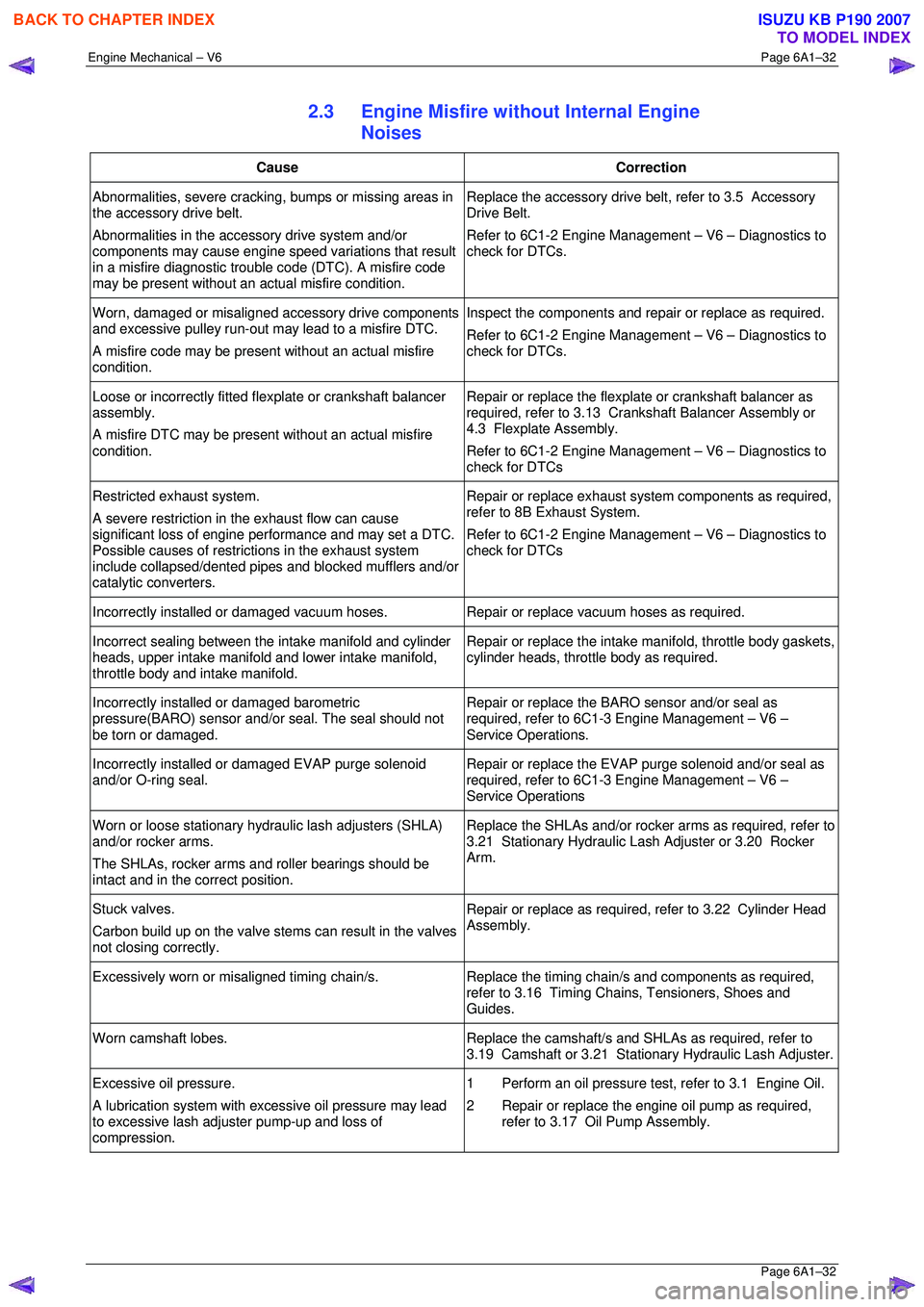
2.3 Engine Misfire without Internal Engine
Noises
Cause Correction
Abnormalities, severe cracking, bumps or missing areas in
the accessory drive belt.
Abnormalities in the accessory drive system and/or
components may cause engine speed variations that result
in a misfire diagnostic trouble code (DTC). A misfire code
may be present without an ac tual misfire condition. Replace the accessory drive belt, refer to 3.5 Accessory
Drive Belt.
Refer to 6C1-2 Engine Management – V6 – Diagnostics to
check for DTCs.
Worn, damaged or misaligned accessory drive components
and excessive pulley run-out may lead to a misfire DTC.
A misfire code may be present without an actual misfire
condition. Inspect the components and repair or replace as required.
Refer to 6C1-2 Engine Management – V6 – Diagnostics to
check for DTCs.
Loose or incorrectly fitted flexplate or crankshaft balancer
assembly.
A misfire DTC may be present without an actual misfire
condition. Repair or replace the flexplat
e or crankshaft balancer as
required, refer to 3.13 Crankshaft Balancer Assembly or
4.3 Flexplate Assembly.
Refer to 6C1-2 Engine Management – V6 – Diagnostics to
check for DTCs
Restricted exhaust system.
A severe restriction in the exhaust flow can cause
significant loss of engine performance and may set a DTC.
Possible causes of restrict ions in the exhaust system
include collapsed/dented pipes and blocked mufflers and/or
catalytic converters. Repair or replace exhaust syst
em components as required,
refer to 8B Exhaust System.
Refer to 6C1-2 Engine Management – V6 – Diagnostics to
check for DTCs
Incorrectly installed or damaged vacuum hoses. Repair or replace vacuum hoses as required.
Incorrect sealing between the intake manifold and cylinder
heads, upper intake manifold and lower intake manifold,
throttle body and intake manifold. Repair or replace the intake
manifold, throttle body gaskets,
cylinder heads, throttle body as required.
Incorrectly installed or damaged barometric
pressure(BARO) sensor and/or seal. The seal should not
be torn or damaged. Repair or replace the BARO sensor and/or seal as
required, refer to 6C1-3 Engine Management – V6 –
Service Operations.
Incorrectly installed or damaged EVAP purge solenoid
and/or O-ring seal. Repair or replace the EVAP purge solenoid and/or seal as
required, refer to 6C1-3 Engine Management – V6 –
Service Operations
Worn or loose stationary hydraulic lash adjusters (SHLA)
and/or rocker arms.
The SHLAs, rocker arms and roller bearings should be
intact and in the correct position. Replace the SHLAs and/or rocker arms as required, refer to
3.21 Stationary Hydraulic Las h Adjuster or 3.20 Rocker
Arm.
Stuck valves.
Carbon build up on the valve stem s can result in the valves
not closing correctly. Repair or replace as required, refer to 3.22 Cylinder Head
Assembly.
Excessively worn or misaligned timing chain/s. Replace the timing chain/s and components as required,
refer to 3.16 Timing Chains, Tensioners, Shoes and
Guides.
Worn camshaft lobes. Replace the camshaft/s and SHLAs as required, refer to
3.19 Camshaft or 3.21 Stati onary Hydraulic Lash Adjuster.
Excessive oil pressure.
A lubrication system with ex cessive oil pressure may lead
to excessive lash adjuster pump-up and loss of
compression. 1 Perform an oil pressure tes
t, refer to 3.1 Engine Oil.
2 Repair or replace the engine oil pump as required, refer to 3.17 Oil Pump Assembly.
BACK TO CHAPTER INDEX
TO MODEL INDEX
ISUZU KB P190 2007
Page 3021 of 6020
Engine Mechanical – V6 Page 6A1–244
Page 6A1–244
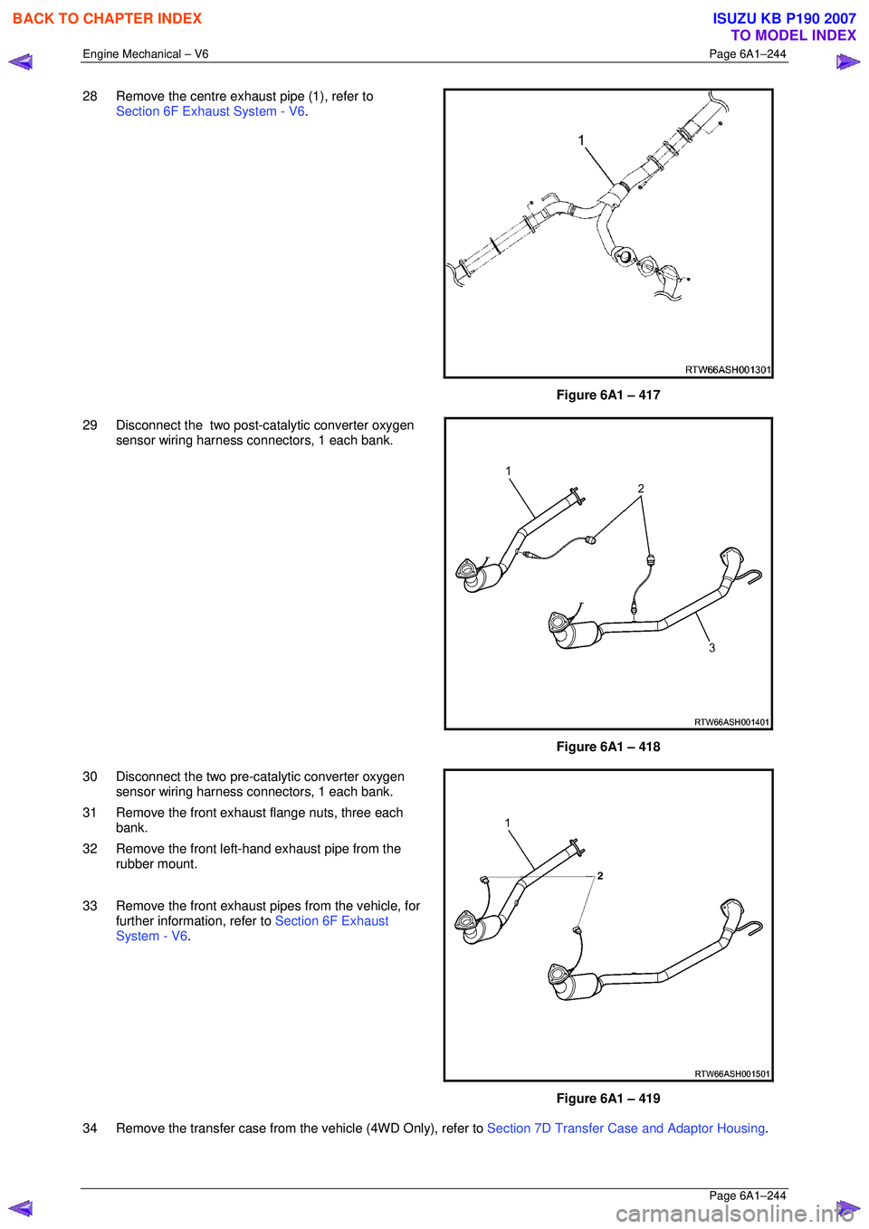
28 Remove the centre exhaust pipe (1), refer to
Section 6F Exhaust System - V6 .
Figure 6A1 – 417
29 Disconnect the two post-catalytic converter oxygen sensor wiring harness connectors, 1 each bank.
Figure 6A1 – 418
30 Disconnect the two pre-catalytic converter oxygen sensor wiring harness connectors, 1 each bank.
31 Remove the front exhaust flange nuts, three each bank.
32 Remove the front left-hand exhaust pipe from the rubber mount.
33 Remove the front exhaust pipes from the vehicle, for further information, refer to Section 6F Exhaust
System - V6 .
Figure 6A1 – 419
34 Remove the transfer case from t he vehicle (4WD Only), refer to Section 7D Transfer Case and Adaptor Housing .
BACK TO CHAPTER INDEX
TO MODEL INDEX
ISUZU KB P190 2007
Page 3269 of 6020
Engine Management – V6 – General Information Page 6C1-1–27
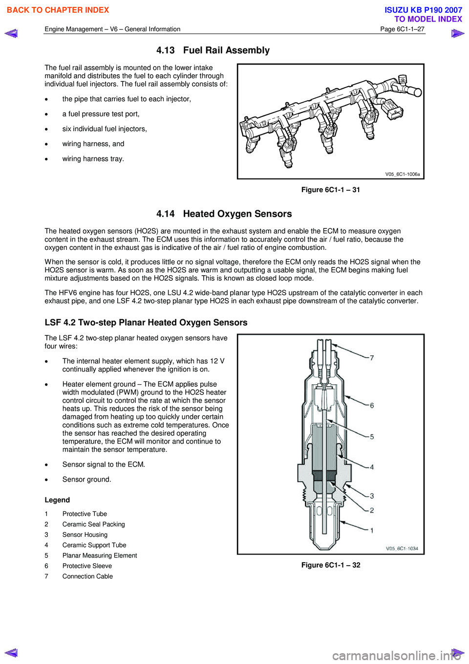
4.13 Fuel Rail Assembly
The fuel rail assembly is mounted on the lower intake
manifold and distributes the fuel to each cylinder through
individual fuel injectors. The fuel rail assembly consists of:
• the pipe that carries fuel to each injector,
• a fuel pressure test port,
• six individual fuel injectors,
• wiring harness, and
• wiring harness tray.
Figure 6C1-1 – 31
4.14 Heated Oxygen Sensors
The heated oxygen sensors (HO2S) are mounted in the exhaust system and enable the ECM to measure oxygen
content in the exhaust stream. The ECM uses this information to accurately control the air / fuel ratio, because the
oxygen content in the exhaust gas is indicative of the air / fuel ratio of engine combustion.
W hen the sensor is cold, it produces little or no signal voltage, therefore the ECM only reads the HO2S signal when the
HO2S sensor is warm. As soon as the HO2S are warm and outputting a usable signal, the ECM begins making fuel
mixture adjustments based on the HO2S signals. This is known as closed loop mode.
The HFV6 engine has four HO2S, one LSU 4.2 wide-band planar type HO2S upstream of the catalytic converter in each
exhaust pipe, and one LSF 4.2 two-step planar type HO2S in each exhaust pipe downstream of the catalytic converter.
LSF 4.2 Two-step Planar Heated Oxygen Sensors
The LSF 4.2 two-step planar heated oxygen sensors have
four wires:
• The internal heater element supply, which has 12 V
continually applied whenever the ignition is on.
• Heater element ground – The ECM applies pulse
width modulated (PW M) ground to the HO2S heater
control circuit to control the rate at which the sensor
heats up. This reduces the risk of the sensor being
damaged from heating up too quickly under certain
conditions such as extreme cold temperatures. Once
the sensor has reached the desired operating
temperature, the ECM will monitor and continue to
maintain the sensor temperature.
• Sensor signal to the ECM.
• Sensor ground.
Legend
1 Protective Tube
2 Ceramic Seal Packing
3 Sensor Housing
4 Ceramic Support Tube
5 Planar Measuring Element
6 Protective Sleeve
7 Connection Cable
Figure 6C1-1 – 32
BACK TO CHAPTER INDEX
TO MODEL INDEX
ISUZU KB P190 2007
Page 3277 of 6020
Engine Management – V6 – General Information Page 6C1-1–35
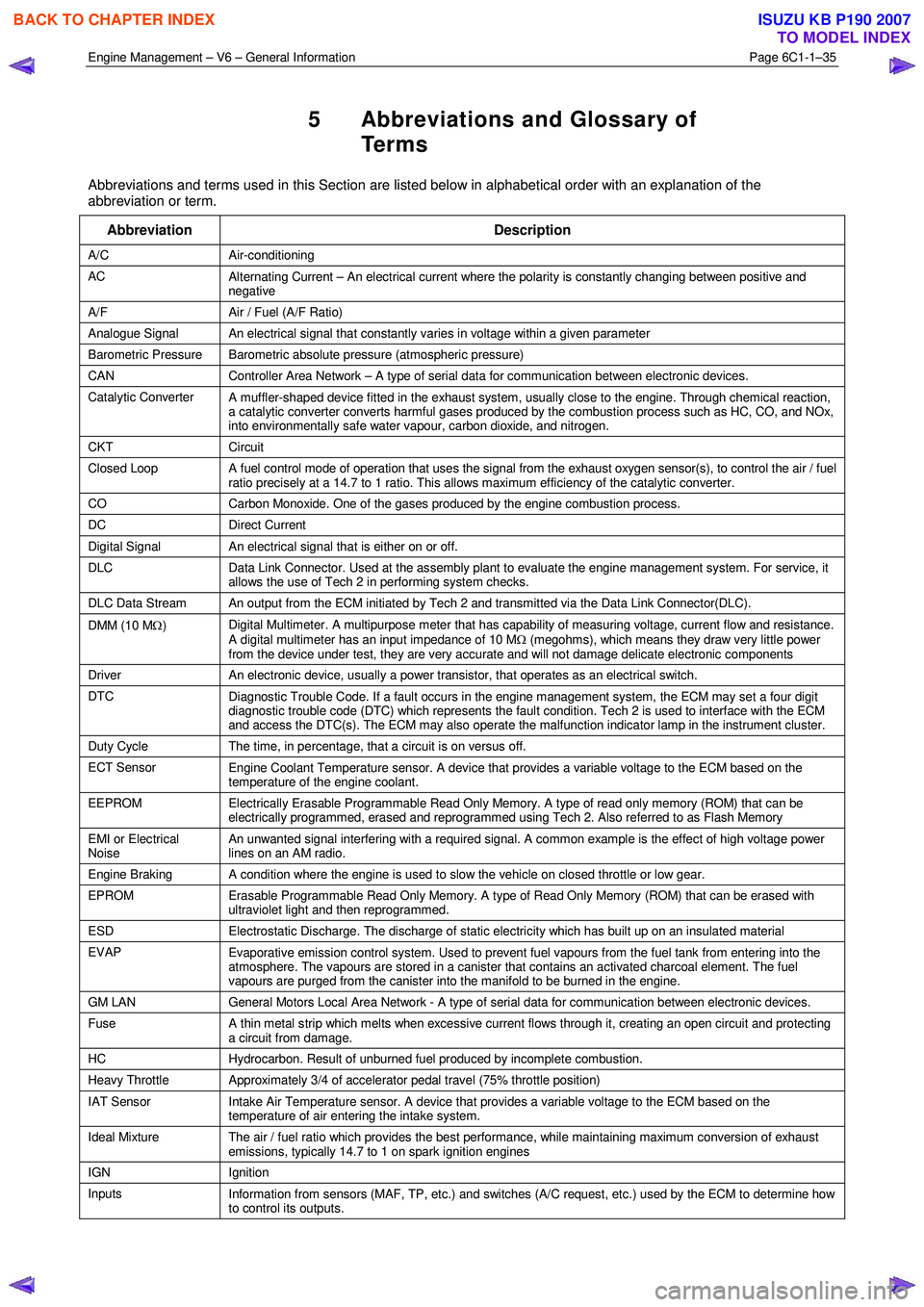
5 Abbreviations and Glossary of
Te r m s
Abbreviations and terms used in this Section are listed below in alphabetical order with an explanation of the
abbreviation or term.
Abbreviation Description
A/C Air-conditioning
AC Alternating Current – An electrical current where the polarity is constantly changing between positive and
negative
A/F Air / Fuel (A/F Ratio)
Analogue Signal An electrical signal that constantly varies in voltage within a given parameter
Barometric Pressure Barometric absolute pressure (atmospheric pressure)
CAN Controller Area Network – A type of serial data for communication between electronic devices.
Catalytic Converter
A muffler-shaped device fitted in the exhaust system, usually close to the engine. Through chemical reaction,
a catalytic converter converts harmful gases produced by the combustion process such as HC, CO, and NOx,
into environmentally safe water vapour, carbon dioxide, and nitrogen.
CKT Circuit
Closed Loop A fuel control mode of operation that uses the signal from the exhaust oxygen sensor(s), to control the air / fuel
ratio precisely at a 14.7 to 1 ratio. This allows maximum efficiency of the catalytic converter.
CO Carbon Monoxide. One of the gases produced by the engine combustion process.
DC Direct Current
Digital Signal An electrical signal that is either on or off.
DLC
Data Link Connector. Used at the assembly plant to evaluate the engine management system. For service, it
allows the use of Tech 2 in performing system checks.
DLC Data Stream An output from the ECM initiated by Tech 2 and transmitted via the Data Link Connector(DLC).
DMM (10 M Ω) Digital Multimeter. A multipurpose meter that has capability of measuring voltage, current flow and resistance.
A digital multimeter has an input impedance of 10 M Ω (megohms), which means they draw very little power
from the device under test, they are very accurate and will not damage delicate electronic components
Driver An electronic device, usually a power transistor, that operates as an electrical switch.
DTC
Diagnostic Trouble Code. If a fault occurs in the engine management system, the ECM may set a four digit
diagnostic trouble code (DTC) which represents the fault condition. Tech 2 is used to interface with the ECM
and access the DTC(s). The ECM may also operate the malfunction indicator lamp in the instrument cluster.
Duty Cycle The time, in percentage, that a circuit is on versus off.
ECT Sensor
Engine Coolant Temperature sensor. A device that provides a variable voltage to the ECM based on the
temperature of the engine coolant.
EEPROM Electrically Erasable Programmable Read Only Memory. A type of read only memory (ROM) that can be
electrically programmed, erased and reprogrammed using Tech 2. Also referred to as Flash Memory
EMI or Electrical
Noise An unwanted signal interfering with a required signal. A common example is the effect of high voltage power
lines on an AM radio.
Engine Braking A condition where the engine is used to slow the vehicle on closed throttle or low gear.
EPROM Erasable Programmable Read Only Memory. A type of Read Only Memory (ROM) that can be erased with
ultraviolet light and then reprogrammed.
ESD Electrostatic Discharge. The discharge of static electricity which has built up on an insulated material
EVAP
Evaporative emission control system. Used to prevent fuel vapours from the fuel tank from entering into the
atmosphere. The vapours are stored in a canister that contains an activated charcoal element. The fuel
vapours are purged from the canister into the manifold to be burned in the engine.
GM LAN General Motors Local Area Network - A type of serial data for communication between electronic devices.
Fuse
A thin metal strip which melts when excessive current flows through it, creating an open circuit and protecting
a circuit from damage.
HC Hydrocarbon. Result of unburned fuel produced by incomplete combustion.
Heavy Throttle Approximately 3/4 of accelerator pedal travel (75% throttle position)
IAT Sensor
Intake Air Temperature sensor. A device that provides a variable voltage to the ECM based on the
temperature of air entering the intake system.
Ideal Mixture The air / fuel ratio which provides the best performance, while maintaining maximum conversion of exhaust
emissions, typically 14.7 to 1 on spark ignition engines
IGN Ignition
Inputs Information from sensors (MAF, TP, etc.) and switches (A/C request, etc.) used by the ECM to determine how
to control its outputs.
BACK TO CHAPTER INDEX
TO MODEL INDEX
ISUZU KB P190 2007