2007 ISUZU KB P190 Harness
[x] Cancel search: HarnessPage 1916 of 6020
ENGINE CONTROL SYSTEM (4JK1/4JJ1) 6E-299
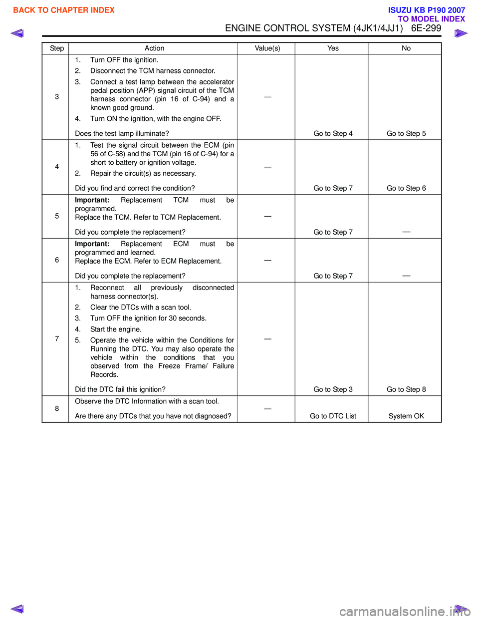
31. Turn OFF the ignition.
2. Disconnect the TCM harness connector.
3. Connect a test lamp between the accelerator pedal position (APP) signal circuit of the TCM
harness connector (pin 16 of C-94) and a
known good ground.
4. Turn ON the ignition, with the engine OFF.
Does the test lamp illuminate? —
Go to Step 4 Go to Step 5
4 1. Test the signal circuit between the ECM (pin
56 of C-58) and the TCM (pin 16 of C-94) for a
short to battery or ignition voltage.
2. Repair the circuit(s) as necessary.
Did you find and correct the condition? —
Go to Step 7 Go to Step 6
5 Important:
Replacement TCM must be
programmed.
Replace the TCM. Refer to TCM Replacement.
Did you complete the replacement? —
Go to Step 7
—
6Important:
Replacement ECM must be
programmed and learned.
Replace the ECM. Refer to ECM Replacement.
Did you complete the replacement? —
Go to Step 7
—
71. Reconnect all previously disconnected
harness connector(s).
2. Clear the DTCs with a scan tool.
3. Turn OFF the ignition for 30 seconds.
4. Start the engine.
5. Operate the vehicle within the Conditions for Running the DTC. You may also operate the
vehicle within the conditions that you
observed from the Freeze Frame/ Failure
Records.
Did the DTC fail this ignition? —
Go to Step 3 Go to Step 8
8 Observe the DTC Information with a scan tool.
Are there any DTCs that you have not diagnosed? —
Go to DTC List System OK
Step
Action Value(s)Yes No
BACK TO CHAPTER INDEX
TO MODEL INDEX
ISUZU KB P190 2007
Page 1917 of 6020
6E-300 ENGINE CONTROL SYSTEM (4JK1/4JJ1)
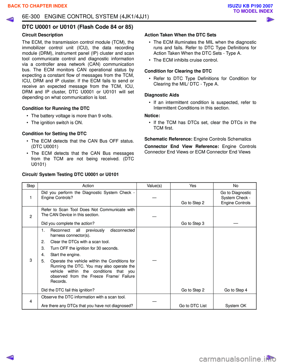
DTC U0001 or U0101 (Flash Code 84 or 85)
Circuit Description
The ECM, the transmission control module (TCM), the
immobilizer control unit (ICU), the data recording
module (DRM), instrument panel (IP) cluster and scan
tool communicate control and diagnostic information
via a controller area network (CAN) communication
bus. The ECM monitors CAN operational status by
expecting a constant flow of messages from the TCM,
ICU, DRM and IP cluster. If the ECM fails to send or
receive an expected message from the TCM, ICU,
DRM and IP cluster, DTC U0001 or U0101 will set
depending on what communication is lost.
Condition for Running the DTC • The battery voltage is more than 9 volts.
• The ignition switch is ON.
Condition for Setting the DTC • The ECM detects that the CAN Bus OFF status. (DTC U0001)
• The ECM detects that the CAN Bus messages from the TCM are not being received. (DTC
U0101) Action Taken When the DTC Sets
• The ECM illuminates the MIL when the diagnostic runs and fails. Refer to DTC Type Definitions for
Action Taken When the DTC Sets - Type A.
• The ECM inhibits cruise control.
Condition for Clearing the DTC • Refer to DTC Type Definitions for Condition for Clearing the MIL/ DTC - Type A.
Diagnostic Aids • If an intermittent condition is suspected, refer to Intermittent Conditions in this section.
Notice: • If the TCM has DTCs set, clear the DTCs in the TCM first.
Schematic Reference: Engine Controls Schematics
Connector End View Reference: Engine Controls
Connector End Views or ECM Connector End Views
Circuit/ System Testing DTC U0001 or U0101
Step Action Value(s)Yes No
1 Did you perform the Diagnostic System Check -
Engine Controls? —
Go to Step 2 Go to Diagnostic
System Check -
Engine Controls
2 Refer to Scan Tool Does Not Communicate with
The CAN Device in this section.
Did you complete the action? —
Go to Step 3
—
31. Reconnect all previously disconnected
harness connector(s).
2. Clear the DTCs with a scan tool.
3. Turn OFF the ignition for 30 seconds.
4. Start the engine.
5. Operate the vehicle within the Conditions for Running the DTC. You may also operate the
vehicle within the conditions that you
observed from the Freeze Frame/ Failure
Records.
Did the DTC fail this ignition? —
Go to Step 2 Go to Step 4
4 Observe the DTC information with a scan tool.
Are there any DTCs that you have not diagnosed? —
Go to DTC List System OK
BACK TO CHAPTER INDEX
TO MODEL INDEX
ISUZU KB P190 2007
Page 1921 of 6020
6E-304 ENGINE CONTROL SYSTEM (4JK1/4JJ1)
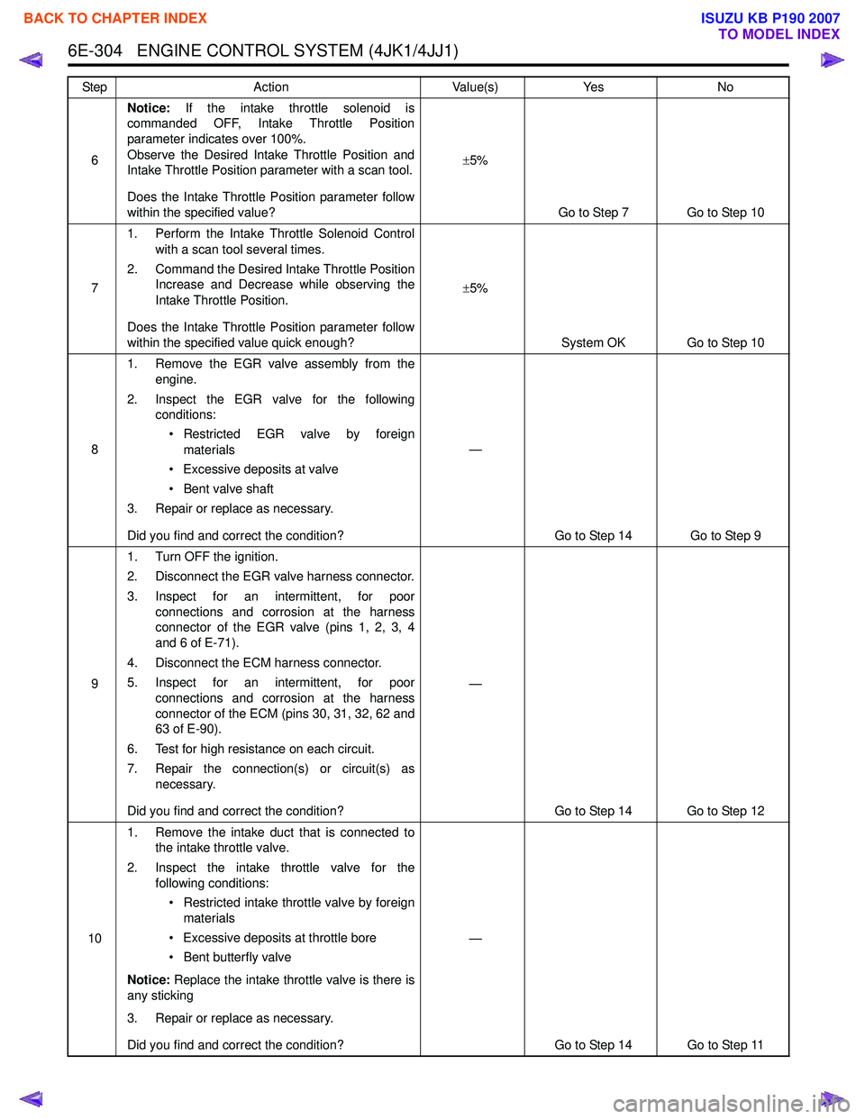
6Notice:
If the intake throttle solenoid is
commanded OFF, Intake Throttle Position
parameter indicates over 100%.
Observe the Desired Intake Throttle Position and
Intake Throttle Position parameter with a scan tool.
Does the Intake Throttle Position parameter follow
within the specified value? ±
5%
Go to Step 7 Go to Step 10
7 1. Perform the Intake Throttle Solenoid Control
with a scan tool several times.
2. Command the Desired Intake Throttle Position Increase and Decrease while observing the
Intake Throttle Position.
Does the Intake Throttle Position parameter follow
within the specified value quick enough? ±
5%
System OK Go to Step 10
8 1. Remove the EGR valve assembly from the
engine.
2. Inspect the EGR valve for the following conditions:
• Restricted EGR valve by foreign materials
• Excessive deposits at valve
• Bent valve shaft
3. Repair or replace as necessary.
Did you find and correct the condition? —
Go to Step 14 Go to Step 9
9 1. Turn OFF the ignition.
2. Disconnect the EGR valve harness connector.
3. Inspect for an intermittent, for poor connections and corrosion at the harness
connector of the EGR valve (pins 1, 2, 3, 4
and 6 of E-71).
4. Disconnect the ECM harness connector.
5. Inspect for an intermittent, for poor connections and corrosion at the harness
connector of the ECM (pins 30, 31, 32, 62 and
63 of E-90).
6. Test for high resistance on each circuit.
7. Repair the connection(s) or circuit(s) as necessary.
Did you find and correct the condition? —
Go to Step 14 Go to Step 12
10 1. Remove the intake duct that is connected to
the intake throttle valve.
2. Inspect the intake throttle valve for the following conditions:
• Restricted intake throttle valve by foreign materials
• Excessive deposits at throttle bore
• Bent butterfly valve
Notice: Replace the intake throttle valve is there is
any sticking
3. Repair or replace as necessary.
Did you find and correct the condition? —
Go to Step 14 Go to Step 11
Step
Action Value(s)Yes No
BACK TO CHAPTER INDEX
TO MODEL INDEX
ISUZU KB P190 2007
Page 1922 of 6020
ENGINE CONTROL SYSTEM (4JK1/4JJ1) 6E-305
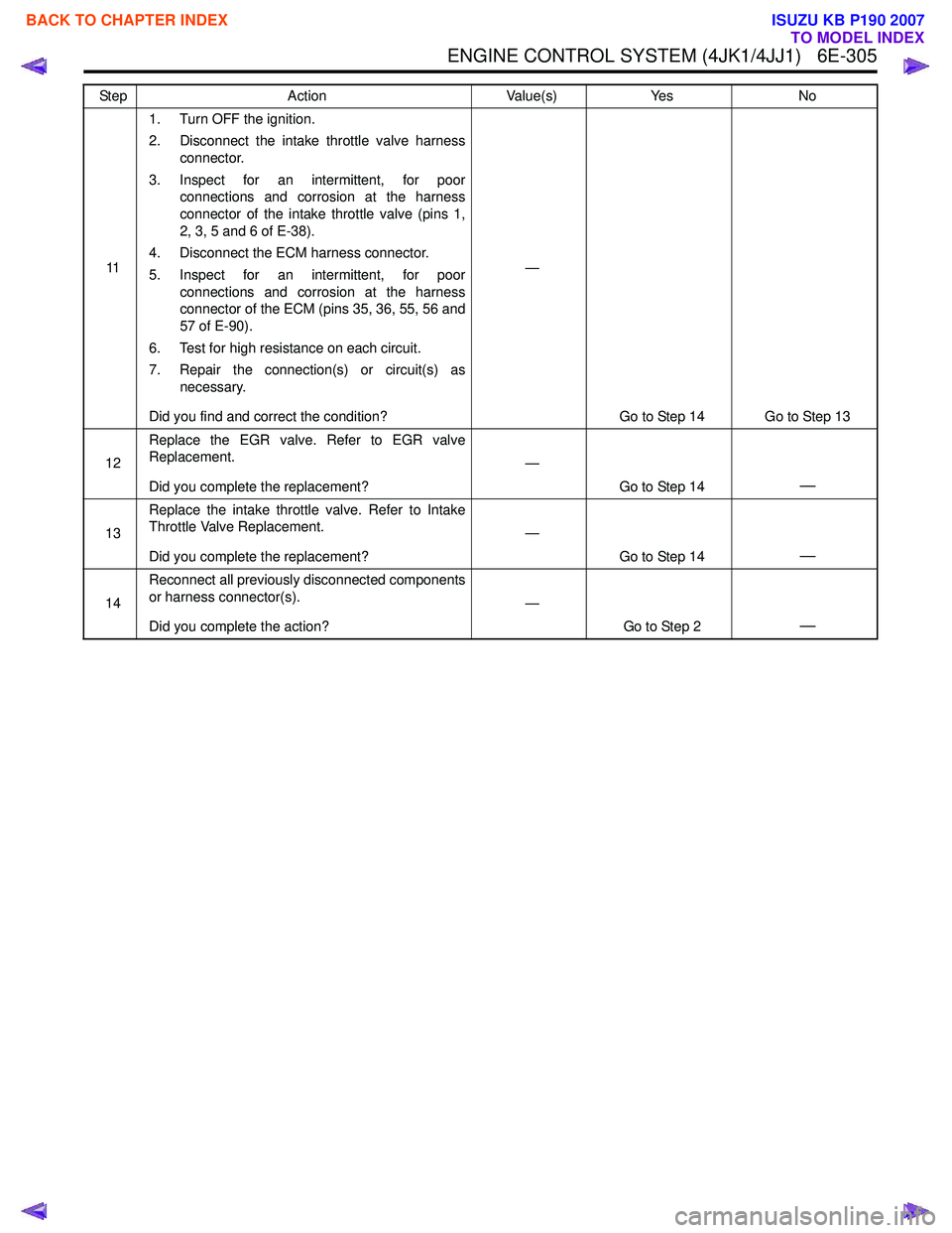
111. Turn OFF the ignition.
2. Disconnect the intake throttle valve harness connector.
3. Inspect for an intermittent, for poor connections and corrosion at the harness
connector of the intake throttle valve (pins 1,
2, 3, 5 and 6 of E-38).
4. Disconnect the ECM harness connector.
5. Inspect for an intermittent, for poor connections and corrosion at the harness
connector of the ECM (pins 35, 36, 55, 56 and
57 of E-90).
6. Test for high resistance on each circuit.
7. Repair the connection(s) or circuit(s) as necessary.
Did you find and correct the condition? —
Go to Step 14 Go to Step 13
12 Replace the EGR valve. Refer to EGR valve
Replacement.
Did you complete the replacement? —
Go to Step 14
—
13Replace the intake throttle valve. Refer to Intake
Throttle Valve Replacement.
Did you complete the replacement? —
Go to Step 14
—
14Reconnect all previously disconnected components
or harness connector(s).
Did you complete the action? —
Go to Step 2
—
Step Action Value(s)Yes No
BACK TO CHAPTER INDEX
TO MODEL INDEX
ISUZU KB P190 2007
Page 1925 of 6020
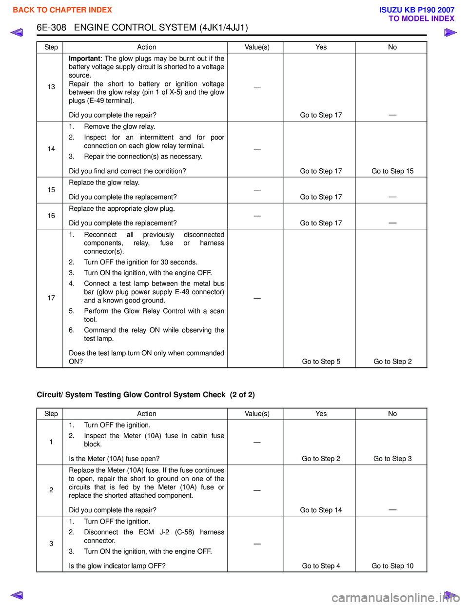
6E-308 ENGINE CONTROL SYSTEM (4JK1/4JJ1)
Circuit/ System Testing Glow Control System Check (2 of 2)
13Important
: The glow plugs may be burnt out if the
battery voltage supply circuit is shorted to a voltage
source.
Repair the short to battery or ignition voltage
between the glow relay (pin 1 of X-5) and the glow
plugs (E-49 terminal).
Did you complete the repair? —
Go to Step 17
—
141. Remove the glow relay.
2. Inspect for an intermittent and for poor connection on each glow relay terminal.
3. Repair the connection(s) as necessary.
Did you find and correct the condition? —
Go to Step 17 Go to Step 15
15 Replace the glow relay.
Did you complete the replacement? —
Go to Step 17
—
16Replace the appropriate glow plug.
Did you complete the replacement? —
Go to Step 17—
171. Reconnect all previously disconnected
components, relay, fuse or harness
connector(s).
2. Turn OFF the ignition for 30 seconds.
3. Turn ON the ignition, with the engine OFF.
4. Connect a test lamp between the metal bus bar (glow plug power supply E-49 connector)
and a known good ground.
5. Perform the Glow Relay Control with a scan tool.
6. Command the relay ON while observing the test lamp.
Does the test lamp turn ON only when commanded
ON? —
Go to Step 5 Go to Step 2
Step
Action Value(s)Yes No
Step Action Value(s)Yes No
1 1. Turn OFF the ignition.
2. Inspect the Meter (10A) fuse in cabin fuse block.
Is the Meter (10A) fuse open? —
Go to Step 2 Go to Step 3
2 Replace the Meter (10A) fuse. If the fuse continues
to open, repair the short to ground on one of the
circuits that is fed by the Meter (10A) fuse or
replace the shorted attached component.
Did you complete the repair? —
Go to Step 14
—
31. Turn OFF the ignition.
2. Disconnect the ECM J-2 (C-58) harness connector.
3. Turn ON the ignition, with the engine OFF.
Is the glow indicator lamp OFF? —
Go to Step 4 Go to Step 10
BACK TO CHAPTER INDEX
TO MODEL INDEX
ISUZU KB P190 2007
Page 1926 of 6020
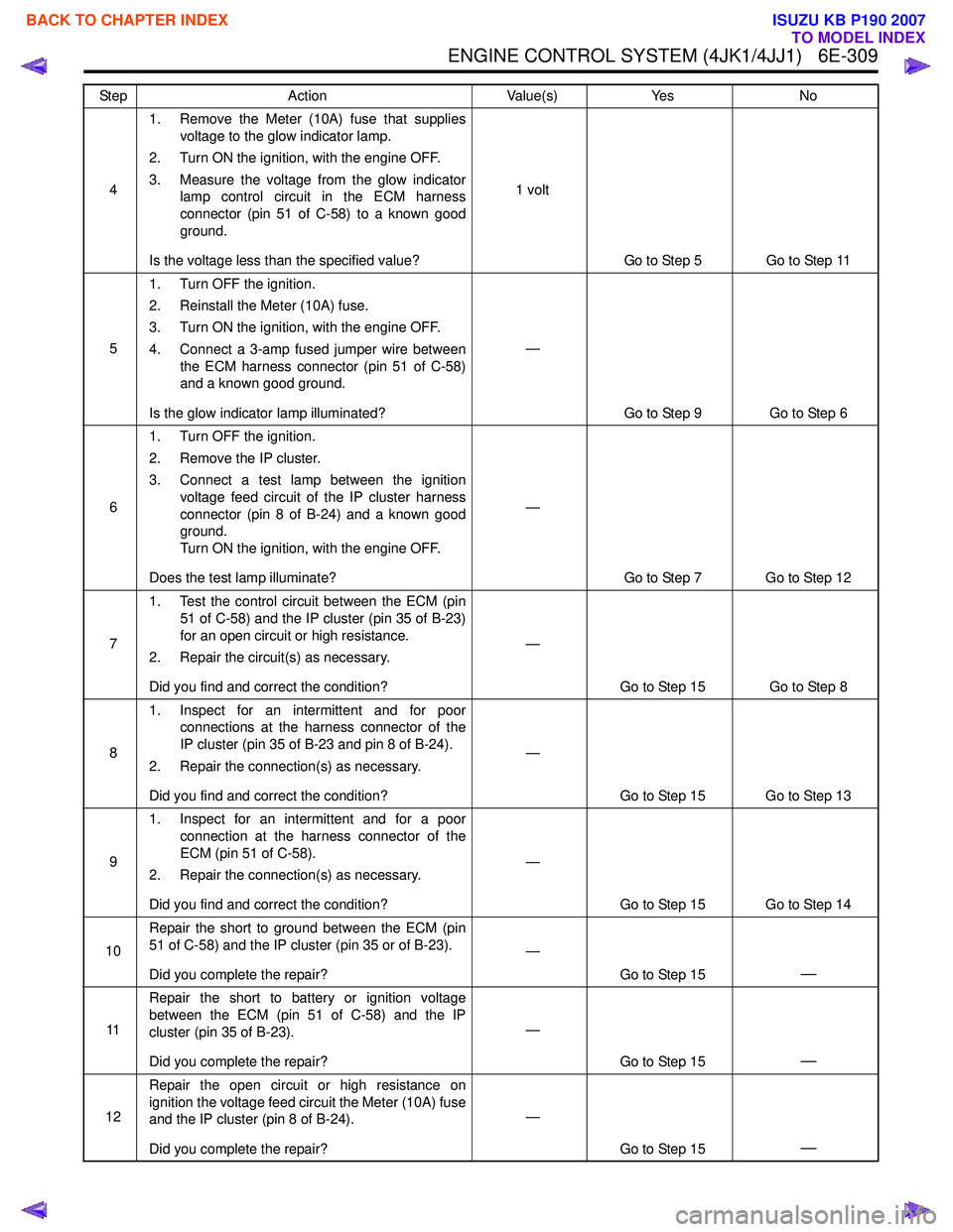
ENGINE CONTROL SYSTEM (4JK1/4JJ1) 6E-309
41. Remove the Meter (10A) fuse that supplies
voltage to the glow indicator lamp.
2. Turn ON the ignition, with the engine OFF.
3. Measure the voltage from the glow indicator lamp control circuit in the ECM harness
connector (pin 51 of C-58) to a known good
ground.
Is the voltage less than the specified value? 1 volt
Go to Step 5 Go to Step 11
5 1. Turn OFF the ignition.
2. Reinstall the Meter (10A) fuse.
3. Turn ON the ignition, with the engine OFF.
4. Connect a 3-amp fused jumper wire between the ECM harness connector (pin 51 of C-58)
and a known good ground.
Is the glow indicator lamp illuminated? —
Go to Step 9 Go to Step 6
6 1. Turn OFF the ignition.
2. Remove the IP cluster.
3. Connect a test lamp between the ignition voltage feed circuit of the IP cluster harness
connector (pin 8 of B-24) and a known good
ground.
Turn ON the ignition, with the engine OFF.
Does the test lamp illuminate? —
Go to Step 7 Go to Step 12
7 1. Test the control circuit between the ECM (pin
51 of C-58) and the IP cluster (pin 35 of B-23)
for an open circuit or high resistance.
2. Repair the circuit(s) as necessary.
Did you find and correct the condition? —
Go to Step 15 Go to Step 8
8 1. Inspect for an intermittent and for poor
connections at the harness connector of the
IP cluster (pin 35 of B-23 and pin 8 of B-24).
2. Repair the connection(s) as necessary.
Did you find and correct the condition? —
Go to Step 15 Go to Step 13
9 1. Inspect for an intermittent and for a poor
connection at the harness connector of the
ECM (pin 51 of C-58).
2. Repair the connection(s) as necessary.
Did you find and correct the condition? —
Go to Step 15 Go to Step 14
10 Repair the short to ground between the ECM (pin
51 of C-58) and the IP cluster (pin 35 or of B-23).
Did you complete the repair? —
Go to Step 15
—
11Repair the short to battery or ignition voltage
between the ECM (pin 51 of C-58) and the IP
cluster (pin 35 of B-23).
Did you complete the repair? —
Go to Step 15
—
12Repair the open circuit or high resistance on
ignition the voltage feed circuit the Meter (10A) fuse
and the IP cluster (pin 8 of B-24).
Did you complete the repair? —
Go to Step 15
—
Step Action Value(s)Yes No
BACK TO CHAPTER INDEX
TO MODEL INDEX
ISUZU KB P190 2007
Page 1927 of 6020
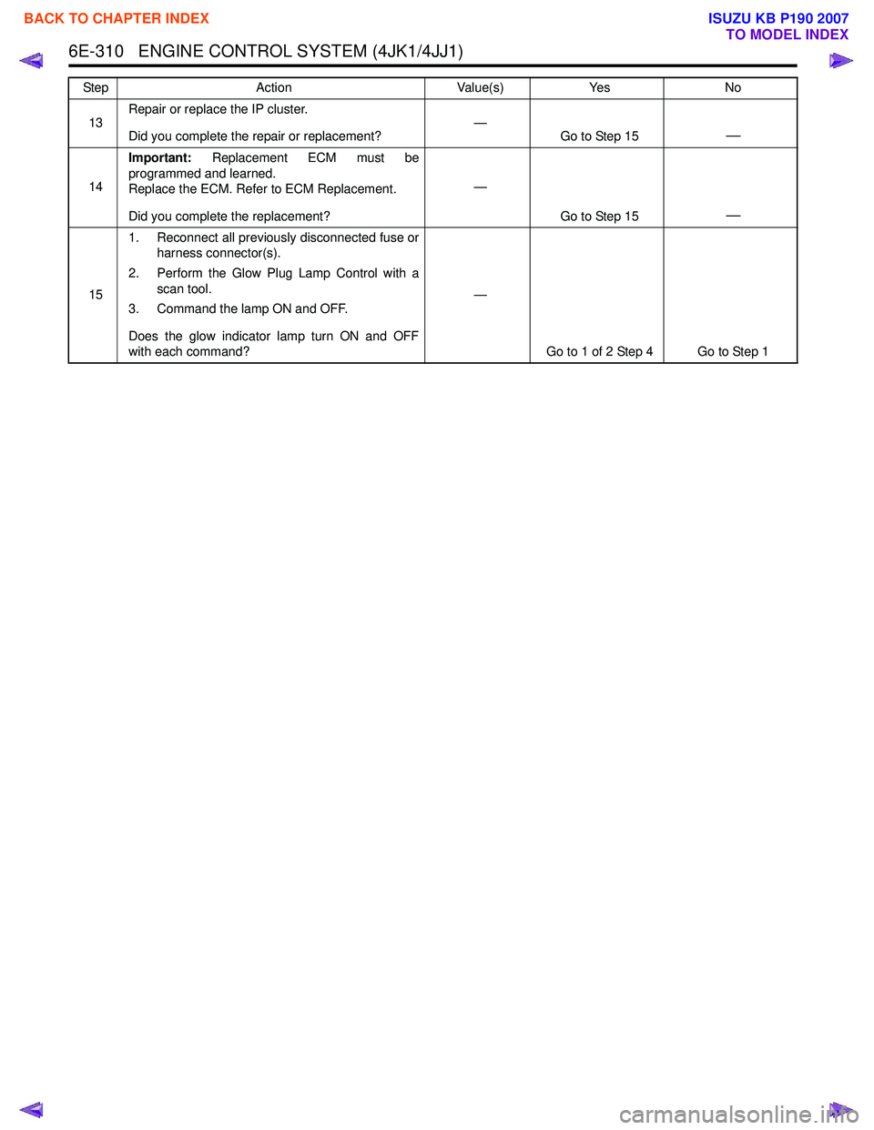
6E-310 ENGINE CONTROL SYSTEM (4JK1/4JJ1)
13Repair or replace the IP cluster.
Did you complete the repair or replacement? —
Go to Step 15—
14Important:
Replacement ECM must be
programmed and learned.
Replace the ECM. Refer to ECM Replacement.
Did you complete the replacement? —
Go to Step 15
—
151. Reconnect all previously disconnected fuse or
harness connector(s).
2. Perform the Glow Plug Lamp Control with a scan tool.
3. Command the lamp ON and OFF.
Does the glow indicator lamp turn ON and OFF
with each command? —
Go to 1 of 2 Step 4 Go to Step 1
Step
Action Value(s)Yes No
BACK TO CHAPTER INDEX
TO MODEL INDEX
ISUZU KB P190 2007
Page 1929 of 6020
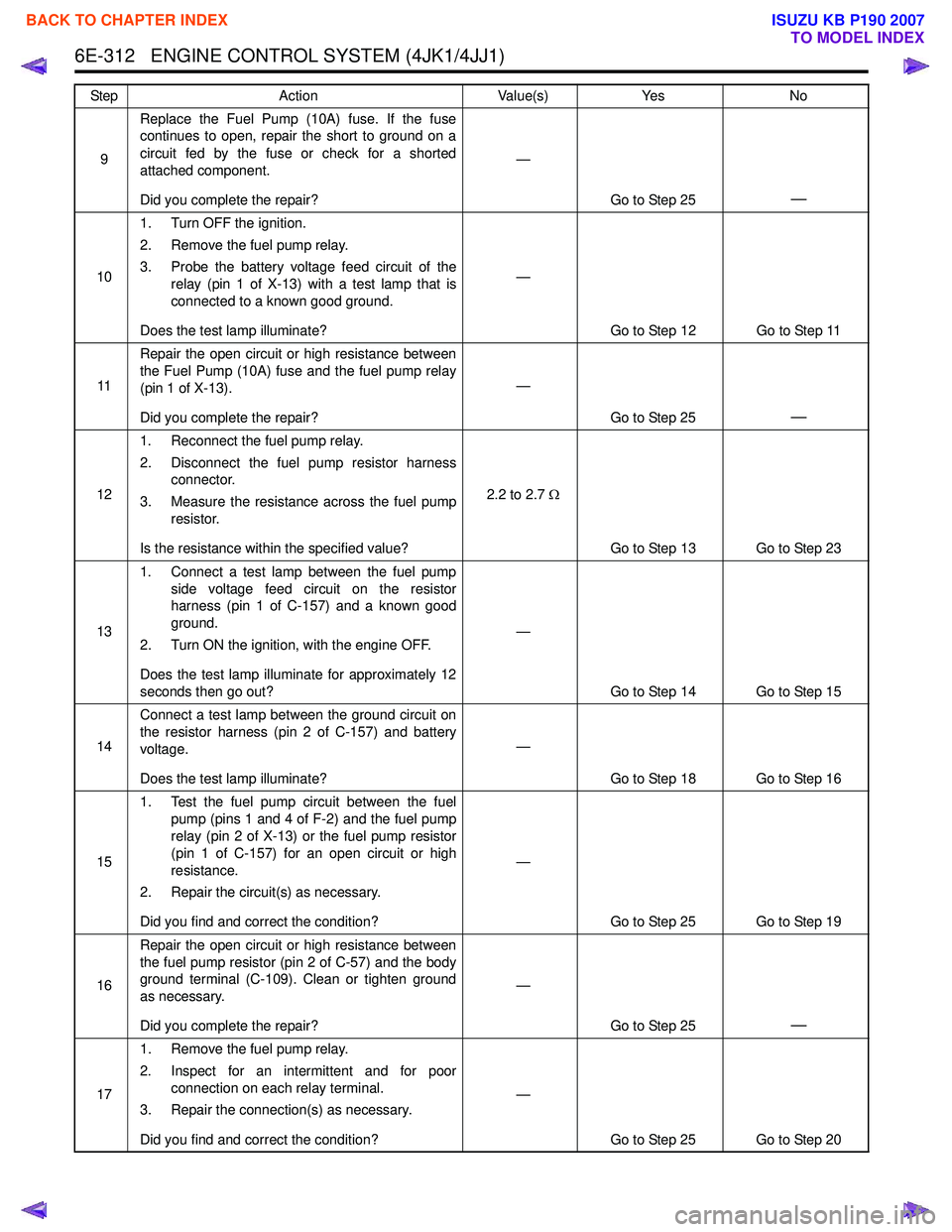
6E-312 ENGINE CONTROL SYSTEM (4JK1/4JJ1)
9Replace the Fuel Pump (10A) fuse. If the fuse
continues to open, repair the short to ground on a
circuit fed by the fuse or check for a shorted
attached component.
Did you complete the repair? —
Go to Step 25
—
101. Turn OFF the ignition.
2. Remove the fuel pump relay.
3. Probe the battery voltage feed circuit of the relay (pin 1 of X-13) with a test lamp that is
connected to a known good ground.
Does the test lamp illuminate? —
Go to Step 12 Go to Step 11
11 Repair the open circuit or high resistance between
the Fuel Pump (10A) fuse and the fuel pump relay
(pin 1 of X-13).
Did you complete the repair? —
Go to Step 25
—
121. Reconnect the fuel pump relay.
2. Disconnect the fuel pump resistor harness connector.
3. Measure the resistance across the fuel pump resistor.
Is the resistance within the specified value? 2.2 to 2.7
Ω
Go to Step 13 Go to Step 23
13 1. Connect a test lamp between the fuel pump
side voltage feed circuit on the resistor
harness (pin 1 of C-157) and a known good
ground.
2. Turn ON the ignition, with the engine OFF.
Does the test lamp illuminate for approximately 12
seconds then go out? —
Go to Step 14 Go to Step 15
14 Connect a test lamp between the ground circuit on
the resistor harness (pin 2 of C-157) and battery
voltage.
Does the test lamp illuminate? —
Go to Step 18 Go to Step 16
15 1. Test the fuel pump circuit between the fuel
pump (pins 1 and 4 of F-2) and the fuel pump
relay (pin 2 of X-13) or the fuel pump resistor
(pin 1 of C-157) for an open circuit or high
resistance.
2. Repair the circuit(s) as necessary.
Did you find and correct the condition? —
Go to Step 25 Go to Step 19
16 Repair the open circuit or high resistance between
the fuel pump resistor (pin 2 of C-57) and the body
ground terminal (C-109). Clean or tighten ground
as necessary.
Did you complete the repair? —
Go to Step 25
—
171. Remove the fuel pump relay.
2. Inspect for an intermittent and for poor connection on each relay terminal.
3. Repair the connection(s) as necessary.
Did you find and correct the condition? —
Go to Step 25 Go to Step 20
Step
Action Value(s)Yes No
BACK TO CHAPTER INDEX
TO MODEL INDEX
ISUZU KB P190 2007