Page 1394 of 6020
6A-34 ENGINE MECHANICAL (4JK1/4JJ1)
Removal
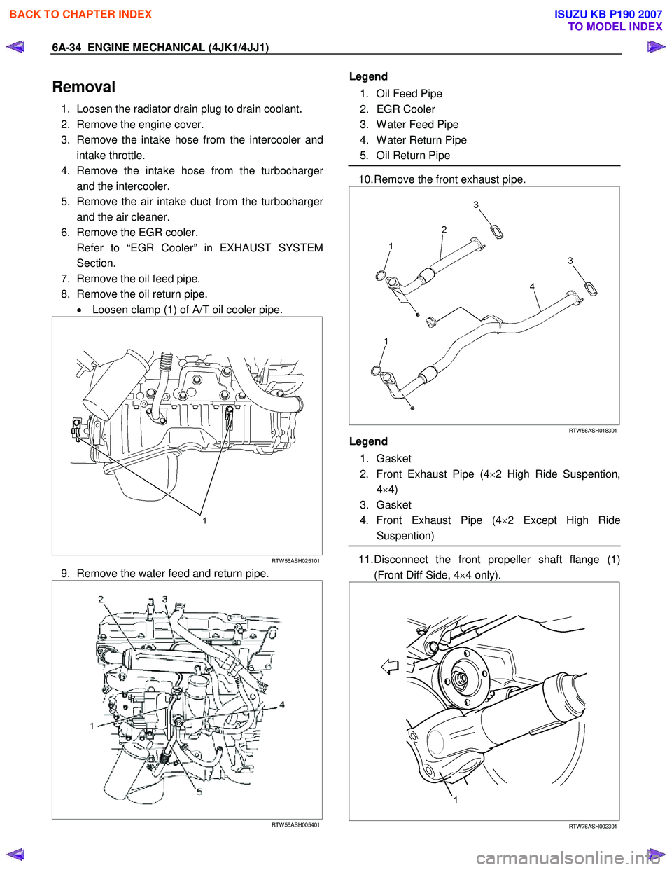
1. Loosen the radiator drain plug to drain coolant.
2. Remove the engine cover.
3. Remove the intake hose from the intercooler and intake throttle.
4. Remove the intake hose from the turbocharge
r
and the intercooler.
5. Remove the air intake duct from the turbocharge
r
and the air cleaner.
6. Remove the EGR cooler.
Refer to “EGR Cooler” in EXHAUST SYSTEM Section.
7. Remove the oil feed pipe.
8. Remove the oil return pipe. • Loosen clamp (1) of A/T oil cooler pipe.
RTW 56ASH025101
9. Remove the water feed and return pipe.
RTW 56ASH005401
Legend
1. Oil Feed Pipe
2. EGR Cooler
3. W ater Feed Pipe
4. W ater Return Pipe
5. Oil Return Pipe
10. Remove the front exhaust pipe.
RTW 56ASH018301
Legend
1. Gasket
2. Front Exhaust Pipe (4 ×2 High Ride Suspention,
4 ×4)
3. Gasket
4. Front Exhaust Pipe (4 ×2 Except High Ride
Suspention)
11. Disconnect the front propeller shaft flange (1)
(Front Diff Side, 4 ×4 only).
RTW 76ASH002301
BACK TO CHAPTER INDEX
TO MODEL INDEX
ISUZU KB P190 2007
Page 1399 of 6020
ENGINE MECHANICAL (4JK1/4JJ1) 6A-39
9. Tighten the oil return pipe bolts and nuts to the
specified torque.
Tightening torque (Turbocharger side): 10 N ⋅
⋅⋅
⋅
m (1.0 kg ⋅
⋅⋅
⋅
m / 87 lb in)
Tightening torque (Crank case side): 25 N ⋅
⋅⋅
⋅
m (2.5 kg ⋅
⋅⋅
⋅
m / 18 lb ft)
10.Install the EGR cooler. • Refer to “EGR Cooler” in EXHAUST SYSTEM
section.
11. Install the heat protector. • Refer to “EGR Cooler” in EXHAUST SYSTEM
section.
12. Install the intake hose between the intercooler and the intake throttle (7).
13. Install the intake hose between the turbocharge
r
and the intercooler (9).
14. Install the intake duct between the turbocharge
r
and the air cleaner (8).
Tightening torque: 6 N ⋅
⋅⋅
⋅
m (0.6 kg ⋅
⋅⋅
⋅
m / 52 lb in)
15.Replenish the coolant.
BACK TO CHAPTER INDEX
TO MODEL INDEX
ISUZU KB P190 2007
Page 1402 of 6020

6A-42 ENGINE MECHANICAL (4JK1/4JJ1)
Removal
1. Drain the engine coolant.
2. Remove the engine cover.
3. Remove the intercooler. • Disconnect the BARO sensor harness
connector (2).
• Remove the two intake hoses.
• Remove the intercooler (1).
RTW 76ASH000501
4. Disconnect the vacuum hose from the
turbocharger actuator.
5. Remove the air intake duct from the turbocharge
r
and the air cleaner.
6. Remove the front exhaust pipe.
RTW 56ASH018301
Legend
1. Gasket
2. Front Exhaust Pipe (4 ×2 High Ride Suspention,
4 ×4)
3. Gasket
4. Front Exhaust Pipe (4 ×2 Except High Ride
Suspention)
7. Remove the heat protector of the turbocharger.
• Remove the mud cover of front RH fender skirt
(4×4 only).
• Loosen the bolt of Turbocharger bracket.
8. Remove the catalyst converter.
9. Remove the turbocharger bracket.
10. Remove the oil feed and return pipe.
11. Remove the water feed and return pipe from the turbocharger.
RTW 76ASH001001
12. Remove the turbocharger from the exhaust
manifold.
BACK TO CHAPTER INDEX
TO MODEL INDEX
ISUZU KB P190 2007
Page 1404 of 6020
6A-44 ENGINE MECHANICAL (4JK1/4JJ1)
3. Place a vernier caliper on the end of the control
rod of actuator. Release the vacuum pressure and
check the control rod moves. Measure the length
of the control rod moving.
Standard length mm (in)
12 (0.48)
Installation
1. Install the gasket and the turbocharger to the
exhaust manifold. Temporarily tighten nuts.
2. Install the oil feed and return pipe and temporaril
y
tighten.
3. Tighten the turbocharger nuts to the specified torque.
Tightening torque: 27 N ⋅
⋅⋅
⋅
m (2.8 kg ⋅
⋅⋅
⋅
m / 20 lb ft)
4. Tighten the oil feed and return pipe bolts and nuts to the specified torque.
Tightening torque (Turbocharger side): 10 N ⋅
⋅⋅
⋅
m (1.0 kg ⋅
⋅⋅
⋅
m / 87 lb in)
Tightening torque (Crank case side): 25 N ⋅
⋅⋅
⋅
m (2.5 kg ⋅
⋅⋅
⋅
m / 18 lb ft)
5. Install the water feed and return pipe to the turbocharger.
Tightening torque: 25 N ⋅
⋅⋅
⋅
m (2.5 kg ⋅
⋅⋅
⋅
m / 18 lb ft)
6. Install the heat protector to the turbocharger. Tightening torque: 10 N ⋅
⋅⋅
⋅
m (1.0 kg ⋅
⋅⋅
⋅
m / 18 lb ft)
7. Install the turbocharger bracket.
8. Install the catalyst converter.
Tighten the nuts to the specified torque.
Tightening torque: 27 N ⋅
⋅⋅
⋅
m (2.8 kg ⋅
⋅⋅
⋅
m / 20 lb ft)
9. Install the mud cover of front RH fender skirt (4 ×4
only).
10. Install the front exhaust pipe.
Tighten the nuts to the specified torque.
Tightening torque
Exhaust Manifold Side: 67 N⋅
⋅⋅
⋅m (6.8 kg⋅
⋅⋅
⋅m / 49 lb ft)
Exhaust Pipe Side: 43 N
⋅
⋅⋅
⋅
m (4.4 kg ⋅
⋅⋅
⋅
m / 32lb ft)
11. Install the intercooler. • Install the intercooler.
• Install the two intake hoses.
• Connect the BARO sensor harness connector.
12. Install the intake duct between the turbocharge
r
and the air cleaner.
Tightening torque: 6 N ⋅
⋅⋅
⋅
m (0.6 kg ⋅
⋅⋅
⋅
m / 52 lb in)
13.Replenish the coolant.
BACK TO CHAPTER INDEX
TO MODEL INDEX
ISUZU KB P190 2007
Page 1434 of 6020
6A-74 ENGINE MECHANICAL (4JK1/4JJ1)
8. Remove the A/C compressor adjust pulley.
RTW 56ASH010601
Legend
1. Bolt
2. Nut
9. Remove the battery.
10. Disconnect the A/C compressor connector and A/C compressor with hose.
11. Remove the A/C compressor bracket.
RTW 56ASH024201
Legend
1. A/C Compressor Bracket
2. Intake Duct
3. A/C Compressor
12. Remove the intercooler (High output).
• Disconnect the BARO sensor harness
connector (2).
• Remove the two intake hoses.
• Remove the intercooler (1).
RTW 76ASH000501
13. Remove the intake hose and duct (Standard
output).
RTW 56ASH022501
Legend
1. Intake Hose for Intercooler and Intake Throttle
2. Intake Duct for Turbocharger and Air Cleaner
3. Intake Hose for Turbocharger and Intercooler
BACK TO CHAPTER INDEX
TO MODEL INDEX
ISUZU KB P190 2007
Page 1459 of 6020
ENGINE MECHANICAL (4JK1/4JJ1) 6A-99
67.Install the intercooler (High output).
• Install the intercooler.
• Install the two intake hoses.
• Connect the BARO sensor harness connector.
68. Install the intake hose.
RTW 56ASH022501
Legend
1. Intake Hose for Intercooler and Intake Throttle
2. Intake Duct for Turbocharger and Air Cleaner
3. Intake Hose for Turbocharger and Intercooler
69. Install the engine head cover.
70. Replenish the coolant.
BACK TO CHAPTER INDEX
TO MODEL INDEX
ISUZU KB P190 2007
Page 1626 of 6020
ENGINE CONTROL SYSTEM (4JK1/4JJ1) 6E-9
Schematic and Rounting Diagrams
Fuel System Routing Diagram
Legend1. Fuel rail
2. Fuel pressure limiter
3. Leak off pipe
4. Fuel injector
5. Fuel return pipe
6. Fuel cooler
7. Fuel tank
8. Fuel pump and sender assembly 9. Fuel filler cap
10. Vent valve 11. Fuel feed pipe
12. One-way valve
13. Fuel filter with sedimenter
14. Fuel pressure switch
15. Fuel supply pump
Vacuum Hose Routing Diagram
Legend
1. Swirl control solenoid valve
2. Actuator control vacuum hose
3. Swirl control actuator
4. Brake booster
5. Vacuum pipe
6. Vacuum pump 7. Actuator control vacuum hose
8. Air cleaner
9. Turbocharger nozzle control actuator
10. Solenoid valve ventilation hose 11. Turbocharger nozzle control solenoid valve
RTW76ESF000101
12 3
4
5
117
8
9
10
14
13
12
15
6
RTW76ESF000201
1 2
4
5
6
9
8
3
7
11
High output10
BACK TO CHAPTER INDEX
TO MODEL INDEX
ISUZU KB P190 2007
Page 1712 of 6020
ENGINE CONTROL SYSTEM (4JK1/4JJ1) 6E-95
DTC P0101 (Flash Code 92)
Circuit Description
The mass air flow (MAF) sensor is an air flow meter
that measures the amount of air that enters the engine.
It is fitted between the air cleaner and turbocharger. A
small quantity of air that enters the engine indicates
deceleration or idle speed. A large quantity of air that
enters the engine indicates acceleration or a high load
condition. The ECM will calculate a predicted MAF
value and compares the actual MAF sensor voltage
signal to the predicted MAF value. This comparison will
determine if the signal is stuck, or is too low or too high
for a given operating condition. If the ECM detects that
the actual MAF sensor signal voltage is not within a
predetermined range of the calculated MAF value, this
DTC will set.
Condition for Running the DTC • DTCs P0045, P0102, P0103, P0107, P0108, P 0 11 2 , P 0 11 3 , P 0 11 6 , P 0 11 7 , P 0 11 8 , P 0 1 2 2 ,
P0123, P0234, P0403, P0404, P0405, P0406,
P0638, P0652, P0653, P0698, P0699, P1404,
P2100, P2101, P2103, P2227, P2228 and P2229
are not set.
AND following conditions are met longer than 10
seconds.
• The battery voltage is between 10.0 to 16.0 volts.
• The ignition switch is ON.
• The intake air temperature is less than 110 °C
(230 °F).
• The engine coolant temperature is between 0 to 11 0 °C (32 to 230 °F).
• The engine speed is between 850 to 3700 RPM.
• The EGR control is commanded OFF.
• The intake throttle control is commanded OFF.
• The commanded fuel injection quantity is OFF (accelerator pedal is not depressed).
• The engine run time is longer than 5 seconds. Condition for Setting the DTC
• The ECM detects that the MAF sensor signal voltage is not within a predetermined range of the
calculated MAF value for longer than 10 seconds.
Action Taken When the DTC Sets • The ECM illuminates the MIL when the diagnostic runs and fails. Refer to DTC Type Definitions for
Action Taken When the DTC Sets - Type A.
• The ECM limits fuel injection quantity.
• The ECM inhibits pilot injection.
• The ECM inhibits EGR control.
• The ECM inhibits cruise control.
Condition for Clearing the DTC • Refer to DTC Type Definitions for Condition for Clearing the MIL/ DTC - Type A.
Diagnostic Aids • Any unmetered air that enters the engine downstream of the MAF sensor will cause this
DTC to set.
• High resistance in the MAF sensor circuit will set this DTC.
• A short between the signal circuit of the MAF sensor and the signal circuit of the intake air
temperature (IAT) sensor will skew the MAF
sensor lower than normal at higher air flows.
Notice: • The MAF Sensor parameter on scan tool will only update with engine running or one time after the
key is cycled when the ignition has been turned
OFF for longer than 10 seconds.
Schematic Reference : Engine Controls Schematics
Connector End View Reference : Engine Controls
Connector End Views or ECM Connector End Views
Circuit/ System Testing DTC P0101
Step Action Value(s)Yes No
1 Did you perform the Diagnostic System Check -
Engine Controls? —
Go to Step 2 Go to Diagnostic
System Check -
Engine Controls
BACK TO CHAPTER INDEX
TO MODEL INDEX
ISUZU KB P190 2007