6E-366 ENGINE CONTROL SYSTEM (4JK1/4JJ1)
The EGR valve is mounted on the intake manifold. The
ECM controls the EGR valve opening based on the
engine running condition. The ECM controls the EGR
valve by controlling the solenoid. The solenoid is
controlled based on pulse width modulation (PWM)
signal sent from the ECM. A duty ratio change 0% to
appropriate percentage is EGR valve lift control. To
open the valve, duty ratio is increased. To close the
valve, duty ratio becomes small.
The EGR valve position is detected by the position
sensor, and relayed to the ECM. The position sensor
provides a signal to the ECM on the signal circuit,
which is relative to the position changes of the EGR
valve. The ECM should detect a low signal voltage at a
small lift amount or closed position. The ECM should
detect high signal voltage at a large lift amount.
Intake Throttle Valve
The intake throttle valve is located on the intake
manifold inlet. The ECM controls the intake throttle
valve opening based on the engine running condition.
The ECM controls the intake throttle valve by
controlling the solenoid. The solenoid is controlled
based on pulse width modulation (PWM) signal sent
from the ECM. A duty ratio change 0% to appropriate
percentage is intake throttle valve opening angle
control. To open the valve, duty ratio is increased. To
close the valve, duty ratio becomes small.
The intake throttle valve position is detected by the
position sensor, and relayed to the ECM. The position
sensor provides a signal to the ECM on the signal
circuit, which is relative to the position changes of the
intake throttle valve. The ECM should detect a low
signal voltage at a small opening amount or closed
position. The ECM should detect high signal voltage at
a large opening amount.Turbocharger Description
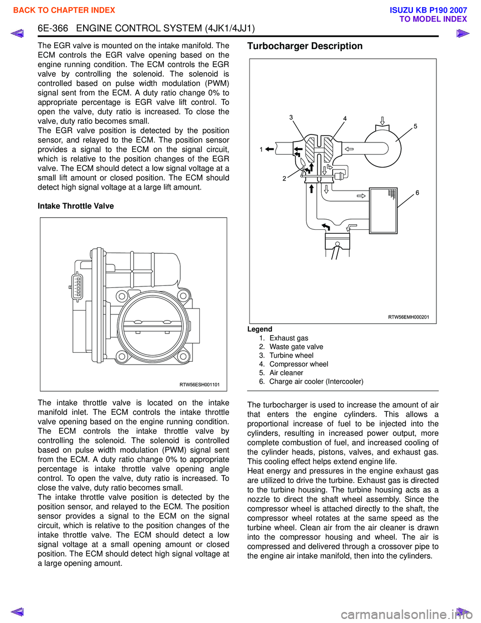
Legend
1. Exhaust gas
2. Waste gate valve
3. Turbine wheel
4. Compressor wheel
5. Air cleaner
6. Charge air cooler (Intercooler)
The turbocharger is used to increase the amount of air
that enters the engine cylinders. This allows a
proportional increase of fuel to be injected into the
cylinders, resulting in increased power output, more
complete combustion of fuel, and increased cooling of
the cylinder heads, pistons, valves, and exhaust gas.
This cooling effect helps extend engine life.
Heat energy and pressures in the engine exhaust gas
are utilized to drive the turbine. Exhaust gas is directed
to the turbine housing. The turbine housing acts as a
nozzle to direct the shaft wheel assembly. Since the
compressor wheel is attached directly to the shaft, the
compressor wheel rotates at the same speed as the
turbine wheel. Clean air from the air cleaner is drawn
into the compressor housing and wheel. The air is
compressed and delivered through a crossover pipe to
the engine air intake manifold, then into the cylinders.
RTW56ESH001101
RTW56EMH000201
1 3
2 4
5
6
BACK TO CHAPTER INDEX
TO MODEL INDEX
ISUZU KB P190 2007
ENGINE CONTROL SYSTEM (4JK1/4JJ1) 6E-367
The amount of air pressure rise and air volume
delivered to the engine from the compressor outlet is
regulated by a waste gate valve in the exhaust housing.
The position of the waste gate valve is controlled by the
amount of pressure built up on the intake side of the
turbocharger. The diaphragm on the inside of the waste
gate is pressure sensitive, and controls the position of
the valve inside the turbocharger. The position of the
valve will increase or decrease the amount of boost to
the turbocharger. (Standard output engine)
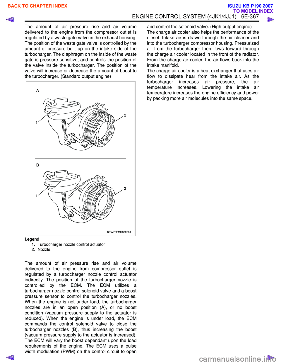
Legend
1. Turbocharger nozzle control actuator
2. Nozzle
The amount of air pressure rise and air volume
delivered to the engine from compressor outlet is
regulated by a turbocharger nozzle control actuator
indirectly. The position of the turbocharger nozzle is
controlled by the ECM. The ECM utilizes a
turbocharger nozzle control solenoid valve and a boost
pressure sensor to control the turbocharger nozzles.
When the engine is not under load, the turbocharger
nozzles are in an open position (A), or no boost
condition (vacuum pressure supply to the actuator is
reduced). When the engine is under load, the ECM
commands the control solenoid valve to close the
turbocharger nozzles (B), thus increasing the boost
(vacuum pressure supply to the actuator is increased).
The ECM will vary the boost dependant upon the load
requirements of the engine. The ECM uses a pulse
width modulation (PWM) on the control circuit to open and control the solenoid valve. (High output engine)
The charge air cooler also helps the performance of the
diesel. Intake air is drawn through the air cleaner and
into the turbocharger compressor housing. Pressurized
air from the turbocharger then flows forward through
the charge air cooler located in the front of the radiator.
From the charge air cooler, the air flows back into the
intake manifold.
The charge air cooler is a heat exchanger that uses air
flow to dissipate hear from the intake air. As the
turbocharger increases air pressure, the air
temperature increases. Lowering the intake air
temperature increases the engine efficiency and power
by packing more air molecules into the same space.
RTW76EMH000201
A
B
1
2
1
2
BACK TO CHAPTER INDEX
TO MODEL INDEX
ISUZU KB P190 2007