2007 ISUZU KB P190 turbo clean
[x] Cancel search: turbo cleanPage 1952 of 6020
ENGINE CONTROL SYSTEM (4JK1/4JJ1) 6E-335
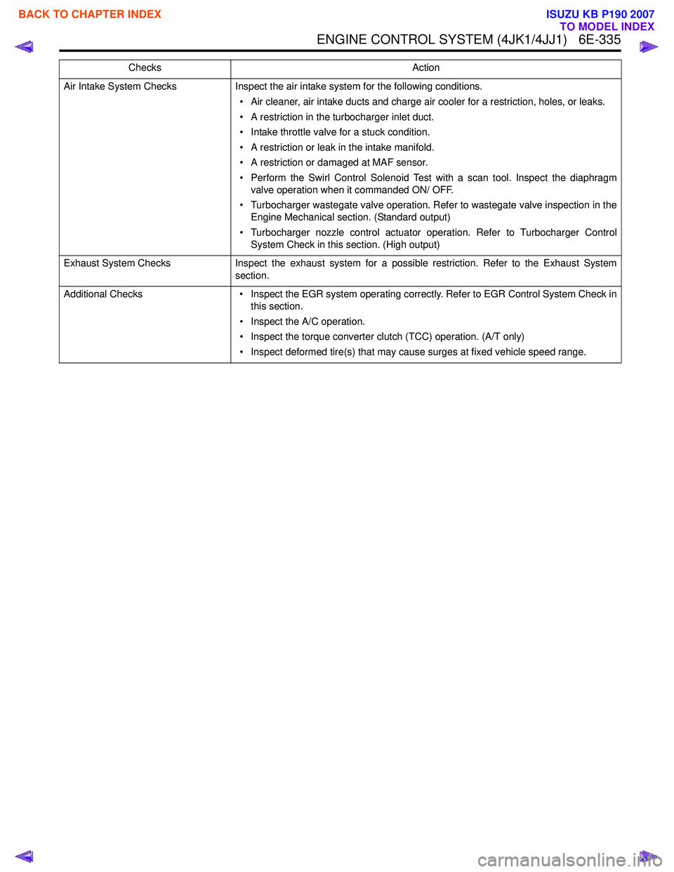
Air Intake System ChecksInspect the air intake system for the following conditions.
• Air cleaner, air intake ducts and charge air cooler for a restriction, holes, or leaks.
• A restriction in the turbocharger inlet duct.
• Intake throttle valve for a stuck condition.
• A restriction or leak in the intake manifold.
• A restriction or damaged at MAF sensor.
• Perform the Swirl Control Solenoid Test with a scan tool. Inspect the diaphragm valve operation when it commanded ON/ OFF.
• Turbocharger wastegate valve operation. Refer to wastegate valve inspection in the Engine Mechanical section. (Standard output)
• Turbocharger nozzle control actuator operation. Refer to Turbocharger Control System Check in this section. (High output)
Exhaust System Checks Inspect the exhaust system for a possible restriction. Refer to the Exhaust System
section.
Additional Checks • Inspect the EGR system operating correctly. Refer to EGR Control System Check in
this section.
• Inspect the A/C operation.
• Inspect the torque converter clutch (TCC) operation. (A/T only)
• Inspect deformed tire(s) that may cause surges at fixed vehicle speed range.
Checks
Action
BACK TO CHAPTER INDEX
TO MODEL INDEX
ISUZU KB P190 2007
Page 1954 of 6020
ENGINE CONTROL SYSTEM (4JK1/4JJ1) 6E-337
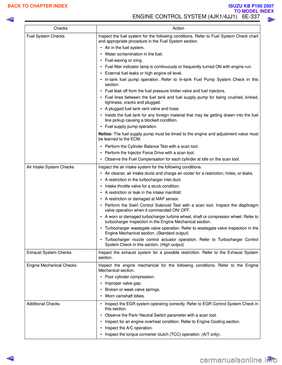
Fuel System ChecksInspect the fuel system for the following conditions. Refer to Fuel System Check chart
and appropriate procedure in the Fuel System section.
• Air in the fuel system.
• Water contamination in the fuel.
• Fuel waxing or icing.
• Fuel filter indicator lamp is continuously or frequently turned ON with engine run.
• External fuel leaks or high engine oil level.
• In-tank fuel pump operation. Refer to In-tank Fuel Pump System Check in this section.
• Fuel leak off from the fuel pressure limiter valve and fuel injectors.
• Fuel lines between the fuel tank and fuel supply pump for being crushed, kinked, tightness, cracks and plugged.
• A plugged fuel tank vent valve and hose.
• Inside the fuel tank for any foreign material that may be getting drawn into the fuel line pickup causing a blocked condition.
• Fuel supply pump operation.
Notice: The fuel supply pump must be timed to the engine and adjustment value must
be learned to the ECM.
• Perform the Cylinder Balance Test with a scan tool.
• Perform the Injector Force Drive with a scan tool.
• Observe the Fuel Compensation for each cylinder at idle on the scan tool.
Air Intake System Checks Inspect the air intake system for the following conditions.
• Air cleaner, air intake ducts and charge air cooler for a restriction, holes, or leaks.
• A restriction in the turbocharger inlet duct.
• Intake throttle valve for a stuck condition.
• A restriction or leak in the intake manifold.
• A restriction or damaged at MAF sensor.
• Perform the Swirl Control Solenoid Test with a scan tool. Inspect the diaphragm valve operation when it commanded ON/ OFF.
• A worn or damaged turbocharger turbine wheel, shaft or compressor wheel. Refer to turbocharger inspection in the Engine Mechanical section.
• Turbocharger wastegate valve operation. Refer to wastegate valve inspection in the Engine Mechanical section. (Standard output)
• Turbocharger nozzle control actuator operation. Refer to Turbocharger Control System Check in this section. (High output)
Exhaust System Checks Inspect the exhaust system for a possible restriction. Refer to the Exhaust System
section.
Engine Mechanical Checks Inspect the engine mechanical for the following conditions. Refer to the Engine
Mechanical section.
• Poor cylinder compression.
• Improper valve gap.
• Broken or weak valve springs.
• Worn camshaft lobes.
Additional Checks • Inspect the EGR system operating correctly. Refer to EGR Control System Check in
this section.
• Observe the Park/ Neutral Switch parameter with a scan tool.
• Inspect for an engine overheat condition. Refer to Engine Cooling section.
• Inspect the A/C operation.
• Inspect the torque converter clutch (TCC) operation. (A/T only).
Checks
Action
BACK TO CHAPTER INDEX
TO MODEL INDEX
ISUZU KB P190 2007
Page 1956 of 6020
ENGINE CONTROL SYSTEM (4JK1/4JJ1) 6E-339
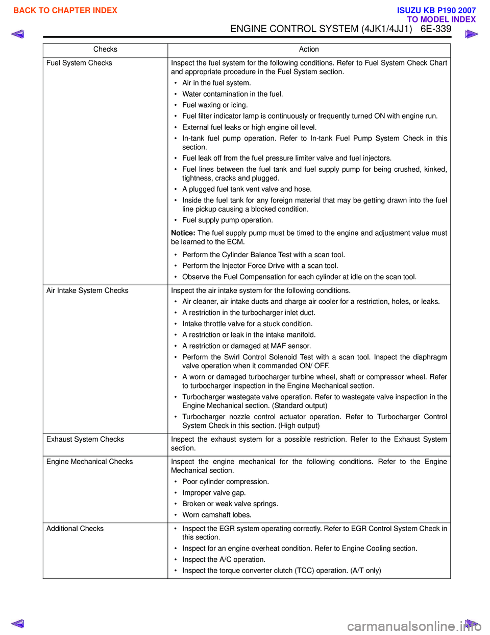
Fuel System ChecksInspect the fuel system for the following conditions. Refer to Fuel System Check Chart
and appropriate procedure in the Fuel System section.
• Air in the fuel system.
• Water contamination in the fuel.
• Fuel waxing or icing.
• Fuel filter indicator lamp is continuously or frequently turned ON with engine run.
• External fuel leaks or high engine oil level.
• In-tank fuel pump operation. Refer to In-tank Fuel Pump System Check in this section.
• Fuel leak off from the fuel pressure limiter valve and fuel injectors.
• Fuel lines between the fuel tank and fuel supply pump for being crushed, kinked, tightness, cracks and plugged.
• A plugged fuel tank vent valve and hose.
• Inside the fuel tank for any foreign material that may be getting drawn into the fuel line pickup causing a blocked condition.
• Fuel supply pump operation.
Notice: The fuel supply pump must be timed to the engine and adjustment value must
be learned to the ECM.
• Perform the Cylinder Balance Test with a scan tool.
• Perform the Injector Force Drive with a scan tool.
• Observe the Fuel Compensation for each cylinder at idle on the scan tool.
Air Intake System Checks Inspect the air intake system for the following conditions.
• Air cleaner, air intake ducts and charge air cooler for a restriction, holes, or leaks.
• A restriction in the turbocharger inlet duct.
• Intake throttle valve for a stuck condition.
• A restriction or leak in the intake manifold.
• A restriction or damaged at MAF sensor.
• Perform the Swirl Control Solenoid Test with a scan tool. Inspect the diaphragm valve operation when it commanded ON/ OFF.
• A worn or damaged turbocharger turbine wheel, shaft or compressor wheel. Refer to turbocharger inspection in the Engine Mechanical section.
• Turbocharger wastegate valve operation. Refer to wastegate valve inspection in the Engine Mechanical section. (Standard output)
• Turbocharger nozzle control actuator operation. Refer to Turbocharger Control System Check in this section. (High output)
Exhaust System Checks Inspect the exhaust system for a possible restriction. Refer to the Exhaust System
section.
Engine Mechanical Checks Inspect the engine mechanical for the following conditions. Refer to the Engine
Mechanical section.
• Poor cylinder compression.
• Improper valve gap.
• Broken or weak valve springs.
• Worn camshaft lobes.
Additional Checks • Inspect the EGR system operating correctly. Refer to EGR Control System Check in
this section.
• Inspect for an engine overheat condition. Refer to Engine Cooling section.
• Inspect the A/C operation.
• Inspect the torque converter clutch (TCC) operation. (A/T only)
Checks
Action
BACK TO CHAPTER INDEX
TO MODEL INDEX
ISUZU KB P190 2007
Page 1959 of 6020
6E-342 ENGINE CONTROL SYSTEM (4JK1/4JJ1)
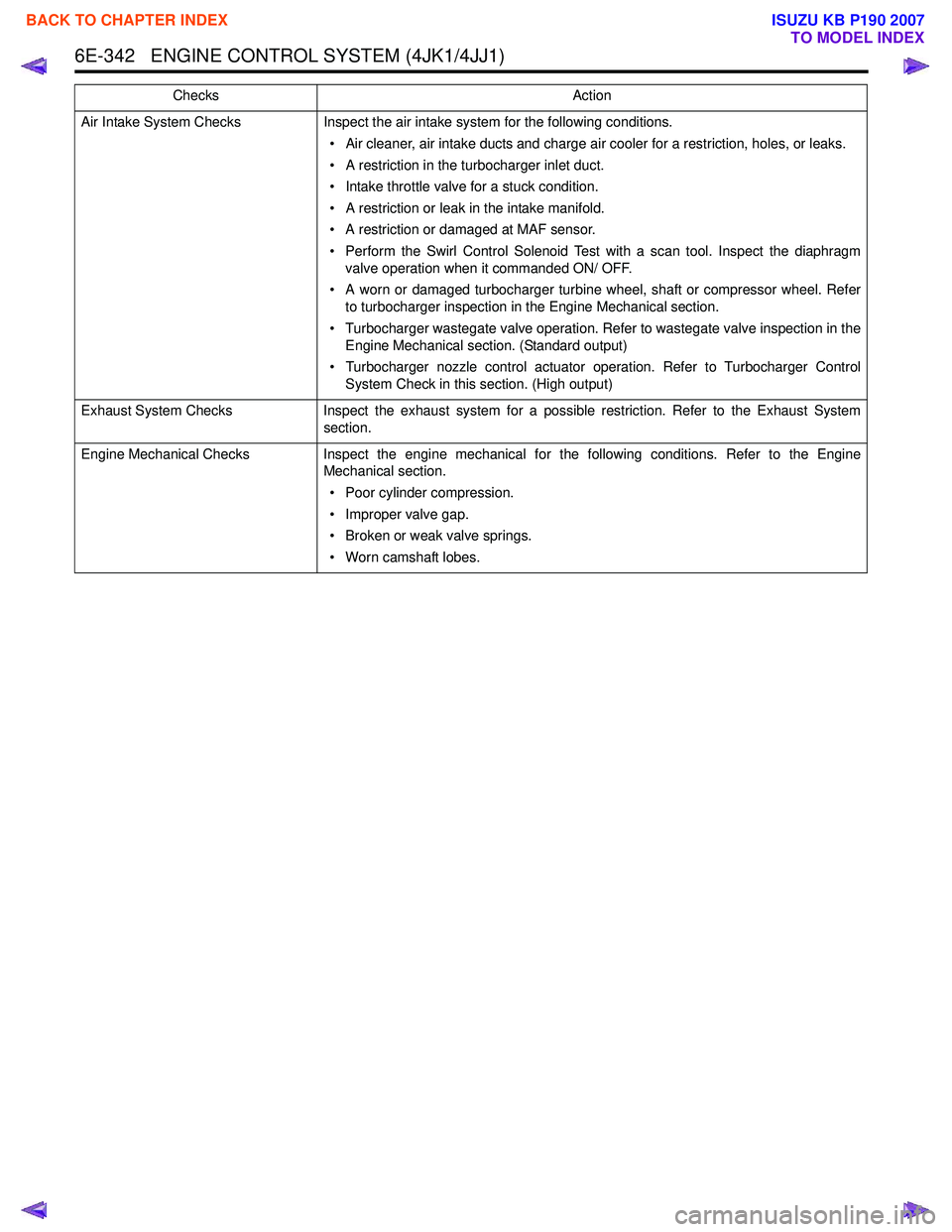
Air Intake System ChecksInspect the air intake system for the following conditions.
• Air cleaner, air intake ducts and charge air cooler for a restriction, holes, or leaks.
• A restriction in the turbocharger inlet duct.
• Intake throttle valve for a stuck condition.
• A restriction or leak in the intake manifold.
• A restriction or damaged at MAF sensor.
• Perform the Swirl Control Solenoid Test with a scan tool. Inspect the diaphragm valve operation when it commanded ON/ OFF.
• A worn or damaged turbocharger turbine wheel, shaft or compressor wheel. Refer to turbocharger inspection in the Engine Mechanical section.
• Turbocharger wastegate valve operation. Refer to wastegate valve inspection in the Engine Mechanical section. (Standard output)
• Turbocharger nozzle control actuator operation. Refer to Turbocharger Control System Check in this section. (High output)
Exhaust System Checks Inspect the exhaust system for a possible restriction. Refer to the Exhaust System
section.
Engine Mechanical Checks Inspect the engine mechanical for the following conditions. Refer to the Engine
Mechanical section.
• Poor cylinder compression.
• Improper valve gap.
• Broken or weak valve springs.
• Worn camshaft lobes.
Checks
Action
BACK TO CHAPTER INDEX
TO MODEL INDEX
ISUZU KB P190 2007
Page 1960 of 6020
ENGINE CONTROL SYSTEM (4JK1/4JJ1) 6E-343
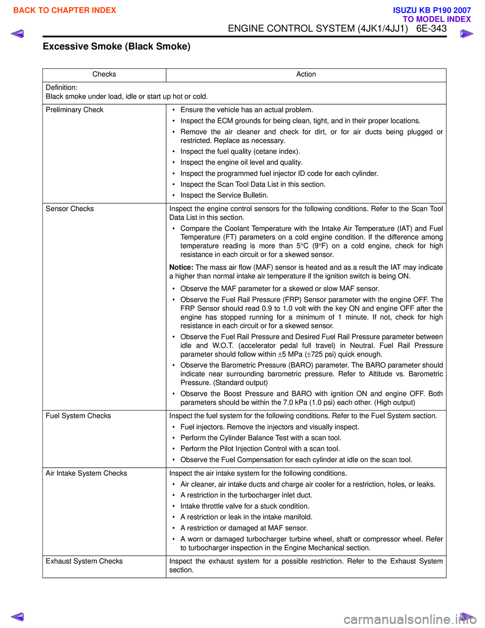
Excessive Smoke (Black Smoke)
ChecksAction
Definition:
Black smoke under load, idle or start up hot or cold.
Preliminary Check • Ensure the vehicle has an actual problem.
• Inspect the ECM grounds for being clean, tight, and in their proper locations.
• Remove the air cleaner and check for dirt, or for air ducts being plugged or restricted. Replace as necessary.
• Inspect the fuel quality (cetane index).
• Inspect the engine oil level and quality.
• Inspect the programmed fuel injector ID code for each cylinder.
• Inspect the Scan Tool Data List in this section.
• Inspect the Service Bulletin.
Sensor Checks Inspect the engine control sensors for the following conditions. Refer to the Scan Tool
Data List in this section.
• Compare the Coolant Temperature with the Intake Air Temperature (IAT) and Fuel Temperature (FT) parameters on a cold engine condition. If the difference among
temperature reading is more than 5 °C (9 °F) on a cold engine, check for high
resistance in each circuit or for a skewed sensor.
Notice: The mass air flow (MAF) sensor is heated and as a result the IAT may indicate
a higher than normal intake air temperature if the ignition switch is being ON.
• Observe the MAF parameter for a skewed or slow MAF sensor.
• Observe the Fuel Rail Pressure (FRP) Sensor parameter with the engine OFF. The FRP Sensor should read 0.9 to 1.0 volt with the key ON and engine OFF after the
engine has stopped running for a minimum of 1 minute. If not, check for high
resistance in each circuit or for a skewed sensor.
• Observe the Fuel Rail Pressure and Desired Fuel Rail Pressure parameter between idle and W.O.T. (accelerator pedal full travel) in Neutral. Fuel Rail Pressure
parameter should follow within ±5 MPa ( ±725 psi) quick enough.
• Observe the Barometric Pressure (BARO) parameter. The BARO parameter should indicate near surrounding barometric pressure. Refer to Altitude vs. Barometric
Pressure. (Standard output)
• Observe the Boost Pressure and BARO with ignition ON and engine OFF. Both parameters should be within the 7.0 kPa (1.0 psi) each other. (High output)
Fuel System Checks Inspect the fuel system for the following conditions. Refer to the Fuel System section.
• Fuel injectors. Remove the injectors and visually inspect.
• Perform the Cylinder Balance Test with a scan tool.
• Perform the Pilot Injection Control with a scan tool.
• Observe the Fuel Compensation for each cylinder at idle on the scan tool.
Air Intake System Checks Inspect the air intake system for the following conditions.
• Air cleaner, air intake ducts and charge air cooler for a restriction, holes, or leaks.
• A restriction in the turbocharger inlet duct.
• Intake throttle valve for a stuck condition.
• A restriction or leak in the intake manifold.
• A restriction or damaged at MAF sensor.
• A worn or damaged turbocharger turbine wheel, shaft or compressor wheel. Refer to turbocharger inspection in the Engine Mechanical section.
Exhaust System Checks Inspect the exhaust system for a possible restriction. Refer to the Exhaust System
section.
BACK TO CHAPTER INDEX
TO MODEL INDEX
ISUZU KB P190 2007
Page 1962 of 6020
ENGINE CONTROL SYSTEM (4JK1/4JJ1) 6E-345
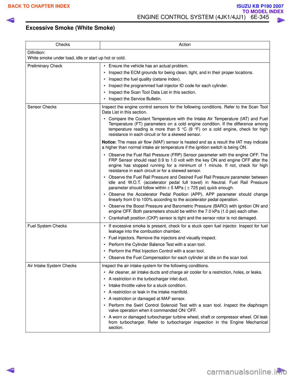
Excessive Smoke (White Smoke)
ChecksAction
Difinition:
White smoke under load, idle or start up hot or cold.
Preliminary Check • Ensure the vehicle has an actual problem.
• Inspect the ECM grounds for being clean, tight, and in their proper locations.
• Inspect the fuel quality (cetane index).
• Inspect the programmed fuel injector ID code for each cylinder.
• Inspect the Scan Tool Data List in this section.
• Inspect the Service Bulletin.
Sensor Checks Inspect the engine control sensors for the following conditions. Refer to the Scan Tool
Data List in this section.
• Compare the Coolant Temperature with the Intake Air Temperature (IAT) and Fuel Temperature (FT) parameters on a cold engine condition. If the difference among
temperature reading is more than 5 °C (9 °F) on a cold engine, check for high
resistance in each circuit or for a skewed sensor.
Notice: The mass air flow (MAF) sensor is heated and as a result the IAT may indicate
a higher than normal intake air temperature if the ignition switch is being ON.
• Observe the Fuel Rail Pressure (FRP) Sensor parameter with the engine OFF. The FRP Sensor should read 0.9 to 1.0 volt with the key ON and engine OFF after the
engine has stopped running for a minimum of 1 minute. If not, check for high
resistance in each circuit or for a skewed sensor.
• Observe the Fuel Rail Pressure and Desired Fuel Rail Pressure parameter between idle and W.O.T. (accelerator pedal full travel) in Neutral. Fuel Rail Pressure
parameter should follow within ± 5 MPa ( ± 725 psi) quick enough.
• Observe the Accelerator Pedal Position (APP). APP parameter should change linearly from 0 to 100% according to the accelerator pedal operation.
• Observe the Boost Pressure and Barometric Pressure (BARO) with ignition ON and engine OFF. Both parameters should be within the 7.0 kPa (1.0 psi) each other.
• Crankshaft position (CKP) sensor is tight and the sensor rotor is not damaged.
Fuel System Checks • If excessive smoke is present, check for a stuck open fuel injector. Inspect for fuel
leakage into the combustion chamber.
• Fuel injectors. Remove the injectors and visually inspect.
• Perform the Cylinder Balance Test with a scan tool.
• Perform the Pilot Injection Control with a scan tool.
• Observe the Fuel Compensation for each cylinder at idle on the scan tool.
Air Intake System Checks Inspect the air intake system for the following conditions.
• Air cleaner, air intake ducts and charge air cooler for a restriction, holes, or leaks.
• A restriction in the turbocharger inlet duct.
• Intake throttle valve for a stuck condition.
• A restriction or leak in the intake manifold.
• A restriction or damaged at MAF sensor.
• Perform the Swirl Control Solenoid Test with a scan tool. Inspect the diaphragm valve operation when it commanded ON/ OFF.
• A worn or damaged turbocharger turbine wheel, shaft or compressor wheel. Oil leak from turbocharger. Refer to turbocharger inspection in the Engine Mechanical
section.
BACK TO CHAPTER INDEX
TO MODEL INDEX
ISUZU KB P190 2007
Page 1975 of 6020
6E-358 ENGINE CONTROL SYSTEM (4JK1/4JJ1)
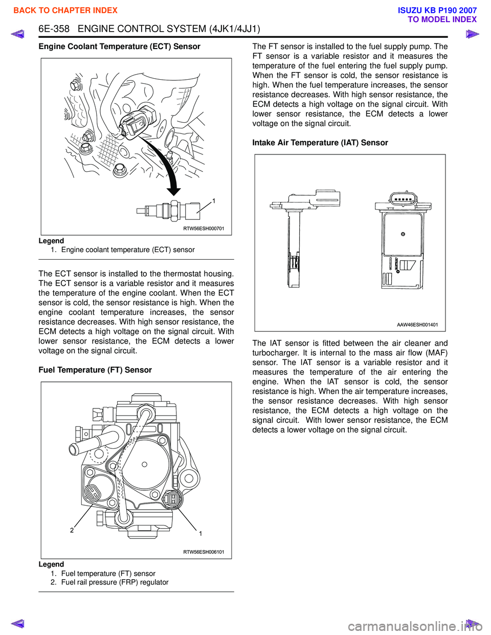
Engine Coolant Temperature (ECT) Sensor
Legend1. Engine coolant temperature (ECT) sensor
The ECT sensor is installed to the thermostat housing.
The ECT sensor is a variable resistor and it measures
the temperature of the engine coolant. When the ECT
sensor is cold, the sensor resistance is high. When the
engine coolant temperature increases, the sensor
resistance decreases. With high sensor resistance, the
ECM detects a high voltage on the signal circuit. With
lower sensor resistance, the ECM detects a lower
voltage on the signal circuit.
Fuel Temperature (FT) Sensor
Legend 1. Fuel temperature (FT) sensor
2. Fuel rail pressure (FRP) regulator
The FT sensor is installed to the fuel supply pump. The
FT sensor is a variable resistor and it measures the
temperature of the fuel entering the fuel supply pump.
When the FT sensor is cold, the sensor resistance is
high. When the fuel temperature increases, the sensor
resistance decreases. With high sensor resistance, the
ECM detects a high voltage on the signal circuit. With
lower sensor resistance, the ECM detects a lower
voltage on the signal circuit.
Intake Air Temperature (IAT) Sensor
The IAT sensor is fitted between the air cleaner and
turbocharger. It is internal to the mass air flow (MAF)
sensor. The IAT sensor is a variable resistor and it
measures the temperature of the air entering the
engine. When the IAT sensor is cold, the sensor
resistance is high. When the air temperature increases,
the sensor resistance decreases. With high sensor
resistance, the ECM detects a high voltage on the
signal circuit. With lower sensor resistance, the ECM
detects a lower voltage on the signal circuit.
RTW56ESH000701
1
RTW56ESH006101
12
AAW46ESH001401
BACK TO CHAPTER INDEX
TO MODEL INDEX
ISUZU KB P190 2007
Page 1976 of 6020
ENGINE CONTROL SYSTEM (4JK1/4JJ1) 6E-359
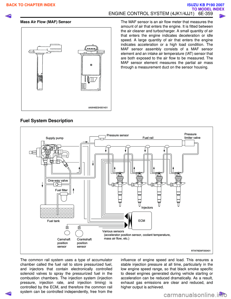
Mass Air Flow (MAF) SensorThe MAF sensor is an air flow meter that measures the
amount of air that enters the engine. It is fitted between
the air cleaner and turbocharger. A small quantity of air
that enters the engine indicates deceleration or idle
speed. A large quantity of air that enters the engine
indicates acceleration or a high load condition. The
MAF sensor assembly consists of a MAF sensor
element and an intake air temperature (IAT) sensor that
are both exposed to the air flow to be measured. The
MAF sensor element measures the partial air mass
through a measurement duct on the sensor housing.
Fuel System Description
The common rail system uses a type of accumulator
chamber called the fuel rail to store pressurized fuel,
and injectors that contain electronically controlled
solenoid valves to spray the pressurized fuel in the
combustion chambers. The injection system (injection
pressure, injection rate, and injection timing) is
controlled by the ECM, and therefore the common rail
system can be controlled independently, free from the influence of engine speed and load. This ensures a
stable injection pressure at all time, particularly in the
low engine speed range, so that black smoke specific
to diesel engines generated during vehicle starting or
acceleration can be reduced dramatically. As a result,
exhaust gas emissions are clear and reduced, and
higher output is achieved.
AAW46ESH001401
RTW76EMF000401
Supply pump
One-way valve
Fuel tank Fuel filter
Camshaft
position
sensor Crankshaft
position
sensor Various sensors
(accelerator position sensor, coolant temperature,
mass air flow, etc.) Injectors
Pressure sensor
Fuel rail Pressure
limiter valve
ECM
BACK TO CHAPTER INDEX
TO MODEL INDEX
ISUZU KB P190 2007