2007 ISUZU KB P190 turbo clean
[x] Cancel search: turbo cleanPage 1308 of 6020
6E-274 Engine Control System (4JH1)
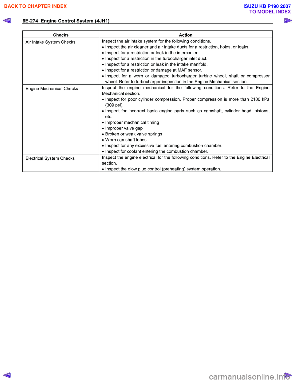
Checks Action
Air Intake System Checks Inspect the air intake system for the following conditions.
• Inspect the air cleaner and air intake ducts for a restriction, holes, or leaks.
• Inspect for a restriction or leak in the intercooler.
• Inspect for a restriction in the turbocharger inlet duct.
• Inspect for a restriction or leak in the intake manifold.
• Inspect for a restriction or damage at MAF sensor.
• Inspect for a worn or damaged turbocharger turbine wheel, shaft or compressor
wheel. Refer to turbocharger inspection in the Engine Mechanical section.
Engine Mechanical Checks Inspect the engine mechanical for the following conditions. Refer to the Engine
Mechanical section.
• Inspect for poor cylinder compression. Proper compression is more than 2100 kPa
(309 psi).
• Inspect for incorrect basic engine parts such as camshaft, cylinder head, pistons,
etc.
• Improper mechanical timing
• Improper valve gap
• Broken or weak valve springs
• W orn camshaft lobes
• Inspect for any excessive fuel entering combustion chamber.
• Inspect for coolant entering the combustion chamber.
Electrical System Checks Inspect the engine electrical for the following conditions. Refer to the Engine Electrical
section.
• Inspect the glow plug control (preheating) system operation.
BACK TO CHAPTER INDEX
TO MODEL INDEX
ISUZU KB P190 2007
Page 1320 of 6020
6E-286 Engine Control System (4JH1)
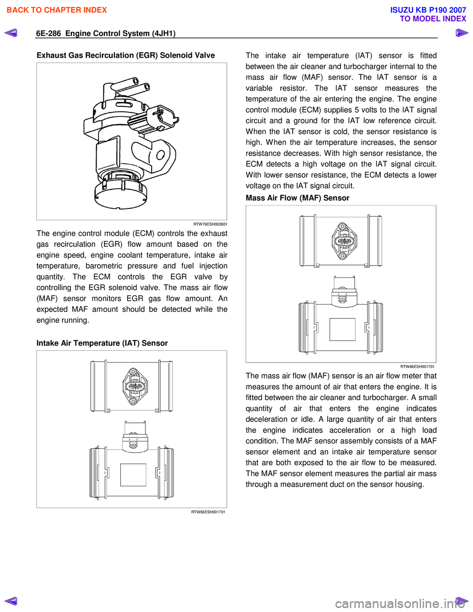
Exhaust Gas Recirculation (EGR) Solenoid Valve
RTW 76ESH003601
The engine control module (ECM) controls the exhaust
gas recirculation (EGR) flow amount based on the
engine speed, engine coolant temperature, intake ai
r
temperature, barometric pressure and fuel injection
quantity. The ECM controls the EGR valve b
y
controlling the EGR solenoid valve. The mass air flo
w
(MAF) sensor monitors EGR gas flow amount. An
expected MAF amount should be detected while the
engine running.
Intake Air Temperature (IAT) Sensor
RTW 66ESH001701
The intake air temperature (IAT) sensor is fitted
between the air cleaner and turbocharger internal to the
mass air flow (MAF) sensor. The IAT sensor is a
variable resistor. The IAT sensor measures the
temperature of the air entering the engine. The engine
control module (ECM) supplies 5 volts to the IAT signal
circuit and a ground for the IAT low reference circuit.
W hen the IAT sensor is cold, the sensor resistance is
high. W hen the air temperature increases, the senso
r
resistance decreases. W ith high sensor resistance, the
ECM detects a high voltage on the IAT signal circuit.
W ith lower sensor resistance, the ECM detects a lowe
r
voltage on the IAT signal circuit.
Mass Air Flow (MAF) Sensor
RTW 66ESH001701
The mass air flow (MAF) sensor is an air flow meter that
measures the amount of air that enters the engine. It is
fitted between the air cleaner and turbocharger. A small
quantity of air that enters the engine indicates
deceleration or idle. A large quantity of air that enters
the engine indicates acceleration or a high load
condition. The MAF sensor assembly consists of a MAF
sensor element and an intake air temperature senso
r
that are both exposed to the air flow to be measured.
The MAF sensor element measures the partial air mass
through a measurement duct on the sensor housing.
BACK TO CHAPTER INDEX
TO MODEL INDEX
ISUZU KB P190 2007
Page 1332 of 6020
6E-298 Engine Control System (4JH1)
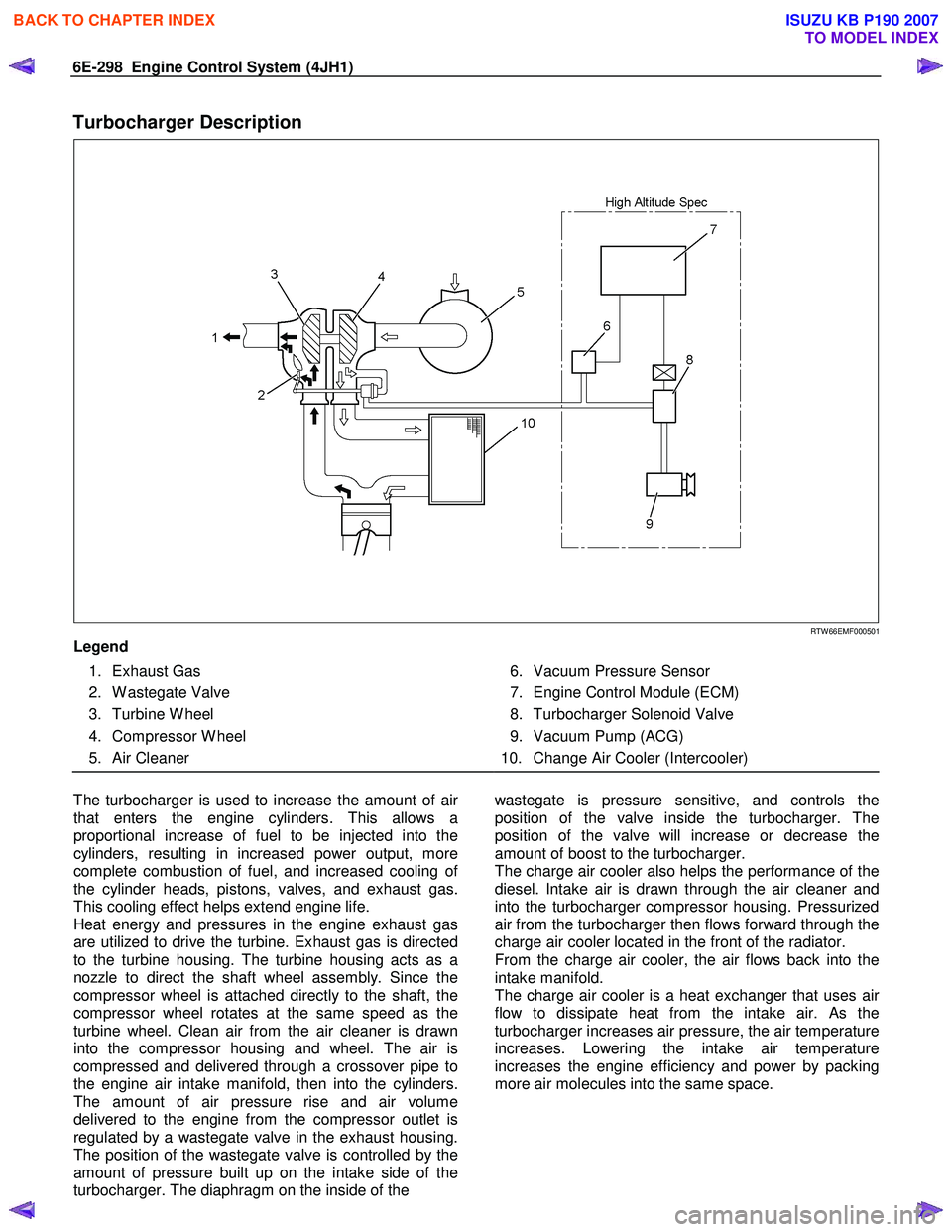
Turbocharger Description
RTW 66EMF000501
Legend
1. Exhaust Gas
2. W astegate Valve
3. Turbine W heel
4. Compressor W heel
5. Air Cleaner
6. Vacuum Pressure Sensor
7. Engine Control Module (ECM)
8. Turbocharger Solenoid Valve
9. Vacuum Pump (ACG)
10. Change Air Cooler (Intercooler)
The turbocharger is used to increase the amount of ai
r
that enters the engine cylinders. This allows a
proportional increase of fuel to be injected into the
cylinders, resulting in increased power output, more
complete combustion of fuel, and increased cooling o
f
the cylinder heads, pistons, valves, and exhaust gas.
This cooling effect helps extend engine life.
Heat energy and pressures in the engine exhaust gas
are utilized to drive the turbine. Exhaust gas is directed
to the turbine housing. The turbine housing acts as a
nozzle to direct the shaft wheel assembly. Since the
compressor wheel is attached directly to the shaft, the
compressor wheel rotates at the same speed as the
turbine wheel. Clean air from the air cleaner is drawn
into the compressor housing and wheel. The air is
compressed and delivered through a crossover pipe to
the engine air intake manifold, then into the cylinders.
The amount of air pressure rise and air volume
delivered to the engine from the compressor outlet is
regulated by a wastegate valve in the exhaust housing.
The position of the wastegate valve is controlled by the
amount of pressure built up on the intake side of the
turbocharger. The diaphragm on the inside of the
wastegate is pressure sensitive, and controls the
position of the valve inside the turbocharger. The
position of the valve will increase or decrease the
amount of boost to the turbocharger.
The charge air cooler also helps the performance of the
diesel. Intake air is drawn through the air cleaner and
into the turbocharger compressor housing. Pressurized
air from the turbocharger then flows forward through the
charge air cooler located in the front of the radiator.
From the charge air cooler, the air flows back into the
intake manifold.
The charge air cooler is a heat exchanger that uses ai
r
flow to dissipate heat from the intake air. As the
turbocharger increases air pressure, the air temperature
increases. Lowering the intake air temperature
increases the engine efficiency and power by packing
more air molecules into the same space.
BACK TO CHAPTER INDEX
TO MODEL INDEX
ISUZU KB P190 2007
Page 1369 of 6020
ENGINE MECHANICAL (4JK1/4JJ1) 6A-9
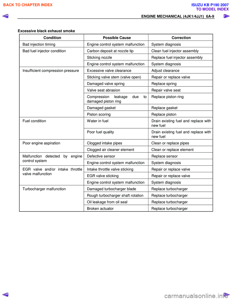
Excessive black exhaust smoke
Condition Possible Cause Correction
Bad injection timing Engine control system malfunction System diagnosis
Carbon deposit at nozzle tip Clean fuel injector assembly
Sticking nozzle Replace fuel injector assembly
Bad fuel injector condition
Engine control system malfunction System diagnosis
Excessive valve clearance Adjust clearance
Sticking valve stem (valve open) Repair or replace valve
Damaged valve spring Replace spring
Valve seat abrasion Repair valve seat
Compression leakage due to
damaged piston ring Replace piston ring
Damaged gasket
Replace gasket
Insufficient compression pressure
Piston scoring Replace piston
W ater in fuel Drain existing fuel and replace with
new fuel Fuel condition
Poor fuel quality Drain existing fuel and replace with
new fuel
Clogged intake pipes Clean or replace pipes Poor engine aspiration
Clogged air cleaner element Clean or replace element
Defective sensor Replace sensor Malfunction detected by engine
control system Engine control system malfunction System diagnosis
Intake throttle valve sticking Repair or replace valve
EGR valve sticking Repair or replace valve
EGR valve and/or intake throttle
valve malfunction
Engine control system malfunction System diagnosis
Damaged turbocharger blade Replace turbocharger
Rough turbocharger shaft rotation Replace turbocharger
Oil leakage from oil seal Replace turbocharger
Turbocharger malfunction
Broken actuator Replace turbocharger
BACK TO CHAPTER INDEX
TO MODEL INDEX
ISUZU KB P190 2007
Page 1370 of 6020
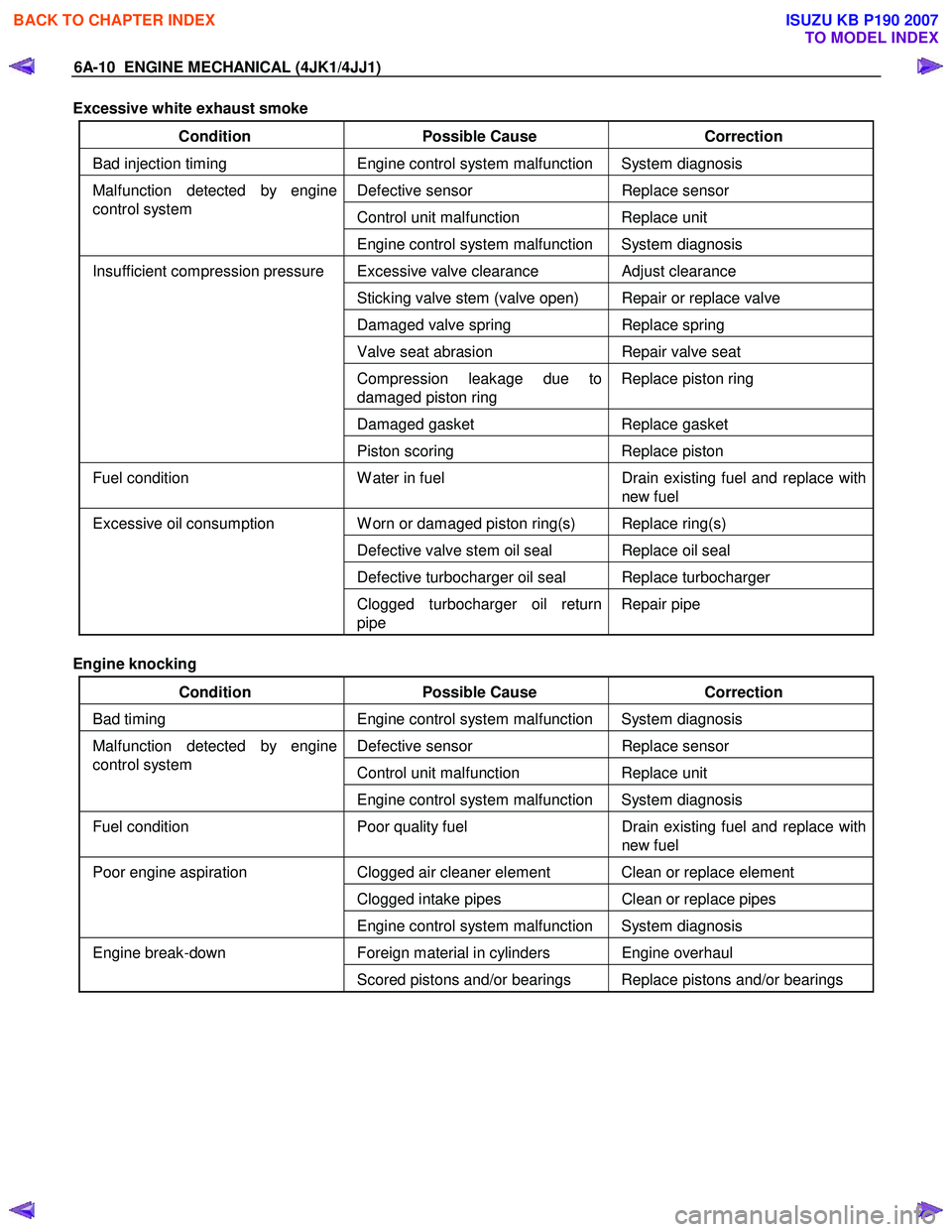
6A-10 ENGINE MECHANICAL (4JK1/4JJ1)
Excessive white exhaust smoke
Condition Possible Cause Correction
Bad injection timing Engine control system malfunction System diagnosis
Defective sensor Replace sensor
Control unit malfunction Replace unit
Malfunction detected by engine
control system
Engine control system malfunction System diagnosis
Excessive valve clearance Adjust clearance
Sticking valve stem (valve open) Repair or replace valve
Damaged valve spring Replace spring
Valve seat abrasion Repair valve seat
Compression leakage due to
damaged piston ring Replace piston ring
Damaged gasket
Replace gasket
Insufficient compression pressure
Piston scoring Replace piston
Fuel condition W ater in fuel Drain existing fuel and replace with
new fuel
W orn or damaged piston ring(s) Replace ring(s)
Defective valve stem oil seal Replace oil seal
Defective turbocharger oil seal Replace turbocharger
Excessive oil consumption
Clogged turbocharger oil return
pipe Repair pipe
Engine knocking
Condition Possible Cause Correction
Bad timing Engine control system malfunction System diagnosis
Defective sensor Replace sensor
Control unit malfunction Replace unit
Malfunction detected by engine
control system
Engine control system malfunction System diagnosis
Fuel condition Poor quality fuel Drain existing fuel and replace with
new fuel
Clogged air cleaner element Clean or replace element
Clogged intake pipes Clean or replace pipes
Poor engine aspiration
Engine control system malfunction System diagnosis
Foreign material in cylinders Engine overhaul Engine break-down Scored pistons and/or bearings Replace pistons and/or bearings
BACK TO CHAPTER INDEX
TO MODEL INDEX
ISUZU KB P190 2007
Page 1372 of 6020
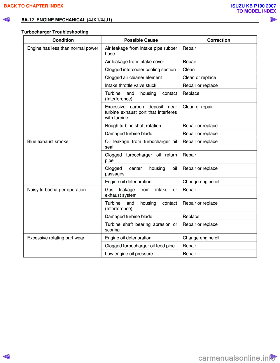
6A-12 ENGINE MECHANICAL (4JK1/4JJ1)
Turbocharger Troubleshooting
Condition Possible Cause Correction
Air leakage from intake pipe rubber
hose Repair
Air leakage from intake cover Repair
Clogged intercooler cooling section Clean
Clogged air cleaner element Clean or replace
Intake throttle valve stuck
Repair or replace
Turbine and housing contact
(Interference) Replace
Excessive carbon deposit near
turbine exhaust port that interferes
with turbine Clean or repair
Rough turbine shaft rotation Repair or replace
Engine has less than normal power
Damaged turbine blade Repair or replace
Oil leakage from turbocharger oil
seal Repair or replace
Clogged turbocharger oil return
pipe Repair
Clogged center housing oil
passages Repair or replace
Blue exhaust smoke
Engine oil deterioration Change engine oil
Gas leakage from intake or
exhaust system Repair
Turbine and housing contact
(Interference) Repair or replace
Damaged turbine blade
Replace
Noisy turbocharger operation
Turbine shaft bearing abrasion or
scoring Repair or replace
Engine oil deterioration
Change engine oil
Clogged turbocharger oil feed pipe Repair
Excessive rotating part wear
Low engine oil pressure Repair
BACK TO CHAPTER INDEX
TO MODEL INDEX
ISUZU KB P190 2007
Page 1375 of 6020
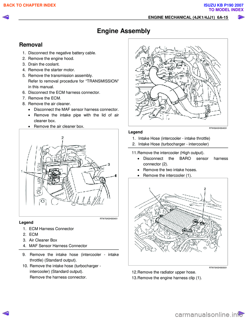
ENGINE MECHANICAL (4JK1/4JJ1) 6A-15
Engine Assembly
Removal
1. Disconnect the negative battery cable.
2. Remove the engine hood.
3. Drain the coolant.
4. Remove the starter motor.
5. Remove the transmission assembly.
Refer to removal procedure for “TRANSMISSION” in this manual.
6. Disconnect the ECM harness connector.
7. Remove the ECM.
8. Remove the air cleaner. • Disconnect the MAF sensor harness connector.
• Remove the intake pipe with the lid of ai
r
cleaner box.
• Remove the air cleaner box.
RTW 76ASH000401
Legend
1. ECM Harness Connector
2. ECM
3. Air Cleaner Box
4. MAF Sensor Harness Connector
9. Remove the intake hose (intercooler - intake
throttle) (Standard output).
10. Remove the intake hose (turbocharger - intercooler) (Standard output).
Remove the harness connector.
RTW 56ASH004001
Legend
1. Intake Hose (intercooler - intake throttle)
2. Intake Hose (turbocharger - intercooler)
11. Remove the intercooler (High output).
• Disconnect the BARO sensor harness
connector (2).
• Remove the two intake hoses.
• Remove the intercooler (1).
RTW 76ASH000501
12. Remove the radiator upper hose.
13. Remove the engine harness clip (1).
BACK TO CHAPTER INDEX
TO MODEL INDEX
ISUZU KB P190 2007
Page 1393 of 6020
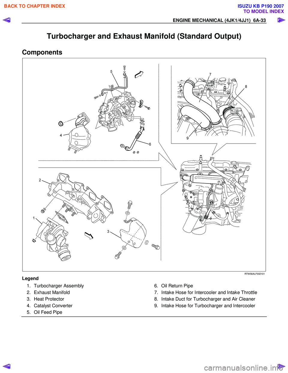
ENGINE MECHANICAL (4JK1/4JJ1) 6A-33
Turbocharger and Exhaust Manifold (Standard Output)
Components
RTW 56ALF002101
Legend 1. Turbocharger Assembly
2. Exhaust Manifold
3. Heat Protector
4. Catalyst Converter
5. Oil Feed Pipe 6. Oil Return Pipe
7. Intake Hose for Intercooler and Intake Throttle
8. Intake Duct for Turbocharger and Air Cleaner
9. Intake Hose for Turbocharger and Intercooler
BACK TO CHAPTER INDEX
TO MODEL INDEX
ISUZU KB P190 2007