Page 5049 of 6020
ELECTRICAL-BODY AND CHASSIS 8A-111
ENGINE CONTROL MODULE (ECM)
PARTS LOCATION (RHD)
RTW 78AXF036301 & RTW 78AXF042501
BACK TO CHAPTER INDEX
TO MODEL INDEXISUZU KB P190 2007
Page 5078 of 6020
8A-140 ELECTRICAL-BODY AND CHASSIS
REMOVAL AND INSTALLATION
ECM (ENGINE CONTROL MODULE);
C24SE
Removal
1. Lift both the ECM harness connector locking levers and
remove the two harness connectors form the ECM.
2. Remove the four socket head screws securing the ECM to the mounting bracket.
3. Remove the ECM from the engine compartment .
4. Pull out the ECM.
5. Disconnect both red and tan connectors.
Refer to the Section 6E-ENGINE of this Manual.
IMPORTANT: The replacement ECM must be programmed.
“SPS (Service Programming System) and immobilizer
programming (if equipped) is/are necessary”
Installation
Follow the removal procedure in the reverse order to install the
ECM.
Pay close attention to the important points mentioned in the
following paragraphs.
Connector
Be absolutely sure that ECM is securely connected.
This will prevent a poor contact and open circuit.
BACK TO CHAPTER INDEX TO MODEL INDEXISUZU KB P190 2007
Page 5079 of 6020

ELECTRICAL-BODY AND CHASSIS 8A-141
REMOVAL AND INSTALLATION
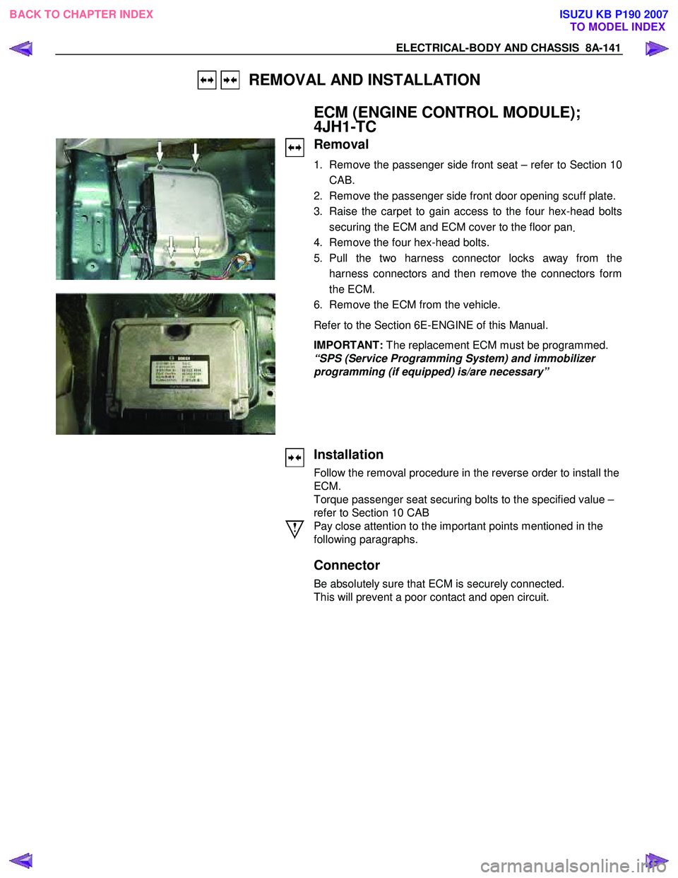
ECM (ENGINE CONTROL MODULE);
4JH1-TC
Removal
1. Remove the passenger side front seat – refer to Section 10
CAB.
2. Remove the passenger side front door opening scuff plate.
3. Raise the carpet to gain access to the four hex-head bolts securing the ECM and ECM cover to the floor pan .
4. Remove the four hex-head bolts.
5. Pull the two harness connector locks away from the harness connectors and then remove the connectors form
the ECM.
6. Remove the ECM from the vehicle.
Refer to the Section 6E-ENGINE of this Manual.
IMPORTANT: The replacement ECM must be programmed.
“SPS (Service Programming System) and immobilizer
programming (if equipped) is/are necessary”
Installation
Follow the removal procedure in the reverse order to install the
ECM.
Torque passenger seat securing bolts to the specified value –
refer to Section 10 CAB
Pay close attention to the important points mentioned in the
following paragraphs.
Connector
Be absolutely sure that ECM is securely connected.
This will prevent a poor contact and open circuit.
BACK TO CHAPTER INDEX TO MODEL INDEXISUZU KB P190 2007
Page 5080 of 6020
8A-142 ELECTRICAL-BODY AND CHASSIS
REMOVAL AND INSTALLATION
FUEL GAUGE UNIT AND SENDER
ASSEMBLY
Removal
1. Remove the fuel gauge unit and sender assembly.
Refer to the “ENGINE FUEL” Section 6C of this Manual.
Installation
To install the fuel gauge unit and sender assembly, follow the
removal procedure in reverse order.
Pay close attention to the important points mentioned in the
following paragraphs.
Rubber Seal
Be absolutely sure that the fuel sender rubber seals are
correctly seated.
Connector
Be absolutely sure that the fuel gauge unit connector is
securely connected.
This will prevent a poor contact and an open circuit.
BACK TO CHAPTER INDEX TO MODEL INDEXISUZU KB P190 2007
Page 5221 of 6020
ELECTRICAL-BODY AND CHASSIS 8A-283
Windshield Washer Spray
Be sure that the engine hood is completely closed before
checking the windshield washer spray adjustment.
W indshield W asher Spray Position: Refer to the illustration.
RTW 38DSF000201
Connector
Be absolutely sure that the wiper motor connector is securely
connected.
This will prevent a poor contact and an open circuit.
Note:
Windshield wiper arm and blade assembly configurations
are different for the right-hand and left-hand side of the
vehicle.
Be careful not to confuse the right-hand and left-hand side
assemblies.
This illustration is based on RHD model
WASHER TANK MOTOR
Removal
1. Remove the head light.
• Refer to the head light in this manual.
2. Remove the inner liner.
3. Pull out the clip washer filler.
4. Remove the washer tank nuts.
BACK TO CHAPTER INDEX TO MODEL INDEXISUZU KB P190 2007
Page 5285 of 6020

ELECTRICAL-BODY AND CHASSIS 8A-347
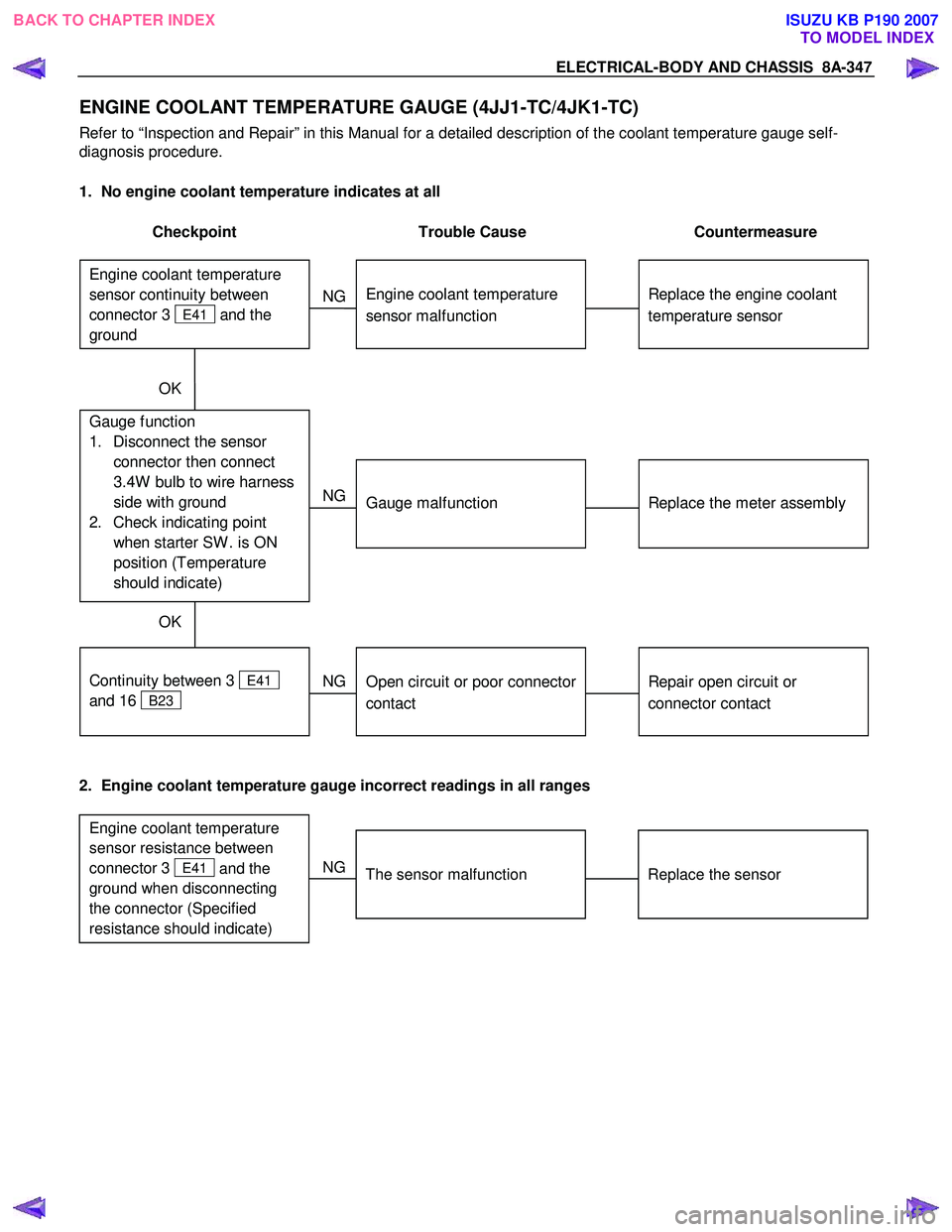
ENGINE COOLANT TEMPERATURE GAUGE (4JJ1-TC/4JK1-TC)
Refer to “Inspection and Repair” in this Manual for a detailed description of the coolant temperature gauge self-
diagnosis procedure.
1. No engine coolant temperature indicates at all
Checkpoint Trouble Cause Countermeasure
Replace the engine coolant
temperature sensor
Engine coolant temperature
sensor malfunction
NG
Replace the meter assembly
Gauge function
1. Disconnect the sensor connector then connect
3.4W bulb to wire harness
side with ground
2. Check indicating point when starter SW . is ON
position (Temperature
should indicate)
Gauge malfunction
Repair open circuit or
connector contact
Continuity between 3
E41
and 16
B23
Open circuit or poor connector
contact
NG
NG
OK
OK
Engine coolant temperature
sensor continuity between
connector 3
E41 and the
ground
2. Engine coolant temperature gauge incorrect readings in all ranges
Replace the sensor
The sensor malfunction
NG
Engine coolant temperature
sensor resistance between
connector 3
E41 and the
ground when disconnecting
the connector (Specified
resistance should indicate)
BACK TO CHAPTER INDEX
TO MODEL INDEXISUZU KB P190 2007
Page 5290 of 6020

8A-352 ELECTRICAL-BODY AND CHASSIS
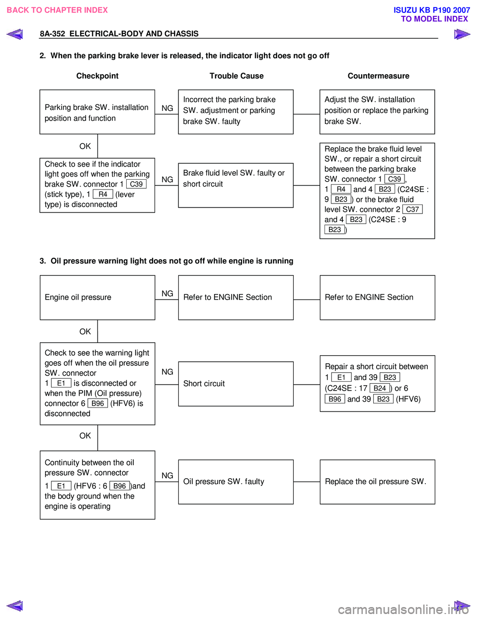
2. When the parking brake lever is released, the indicator light does not go off
Checkpoint Trouble Cause Countermeasure
Adjust the SW . installation
position or replace the parking
brake SW . Incorrect the parking brake
SW . adjustment or parking
brake SW . faulty
NG
Thermo unit malfunction
Replace the brake fluid level
SW ., or repair a short circuit
between the parking brake
SW . connector 1
C39,
1
R4 and 4 B23 (C24SE :
9
B23 ) or the brake fluid
level SW . connector 2
C37
and 4
B23 (C24SE : 9
B23 )
Check to see if the indicator
light goes off when the parking
brake SW . connector 1
C39
(stick type), 1
R4 (lever
type) is disconnected
Brake fluid level SW . faulty or
short circuit
NG
OK
Parking brake SW . installation
position and function
3. Oil pressure warning light does not go off while engine is running
Refer to ENGINE Section
Refer to ENGINE Section
NG Thermo unit malfunction
Check to see the warning light
goes off when the oil pressure
SW . connector
1
E1 is disconnected or
when the PIM (Oil pressure)
connector 6
B96 (HFV6) is
disconnected
Repair a short circuit between
1
E1 and 39 B23
(C24SE : 17
B24) or 6
B96 and 39 B23 (HFV6)
Short circuit
NG
OK
Replace the oil pressure SW .
Continuity between the oil
pressure SW . connector
1
E1 (HFV6 : 6 B96 )and
the body ground when the
engine is operating
Oil pressure SW . faulty
NG
OK
Engine oil pressure
BACK TO CHAPTER INDEX TO MODEL INDEXISUZU KB P190 2007
Page 5298 of 6020
8A-360 ELECTRICAL-BODY AND CHASSIS
Tachometer On-Vehicle Inspection
1. Attach a tune-up tester to the engine.
2. Start the engine.
3. Compare the tachometer reading and the tester reading.
If the tachometer indication is outside the permissible range, the tachometer must be replaced.
4. Gradually increase and decrease the engine speed.
Note the movement of the tachometer needle.
If the needle movement is sluggish, the tachometer must be replaced.
4JJ1-TC/4JA1T(L)/4JH1-TC
RTW 780SH000401
rpm
Indication Permissible Range
750 700-870
2,000 1915-2085
3,000 2915-3085
4,000 3950-4120
5,000 4950-5120
4JK1-TC
RTW 780SH000501
Tachometer rpm
Indication Permissible Range
750 700-870
2,000 1915-2085
3,000 2915-3085
4,000 3950-4120
5,000 4950-5120
C24SE
RTW 78ASH001301
rpm
Indication Permissible Range
1,000 950-1150
2,000 1900-2100
3,000 2900-3100
4,000 3900-4100
5,000 4900-5100
6,000 5950-6150
BACK TO CHAPTER INDEX
TO MODEL INDEXISUZU KB P190 2007