2007 ISUZU KB P190 engine
[x] Cancel search: enginePage 5561 of 6020
ELECTRICAL-BODY AND CHASSIS 8A-623
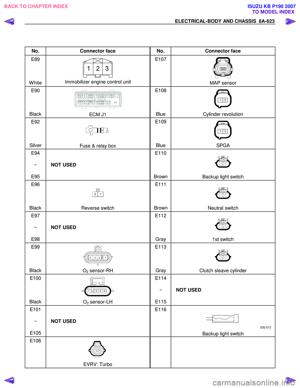
No. Connector face No. Connector face
E89
White
Immobilizer engine control unit E107
MAP sensor
E90
Black
ECM J1 E108
Blue Cylinder revolution
E92
Silver
Fuse & relay box E109
Blue SPGA
E94
~
E95 NOT USED E110
Brown
Backup light switch
E96
Black
Reverse switch E111
BrownNeutral switch
E97
~
E98 NOT USED E112
Gray
1st switch
E99
Black
O2 sensor-RH E113
Gray Clutch sleave cylinder
E100
Black
O2 sensor-LH E114
~
E115 NOT USED
E101
~
E105 NOT USED E116
Backup light switch
E106
EVRV: Turbo
BACK TO CHAPTER INDEX
TO MODEL INDEXISUZU KB P190 2007
Page 5563 of 6020
ELECTRICAL-BODY AND CHASSIS 8A-625
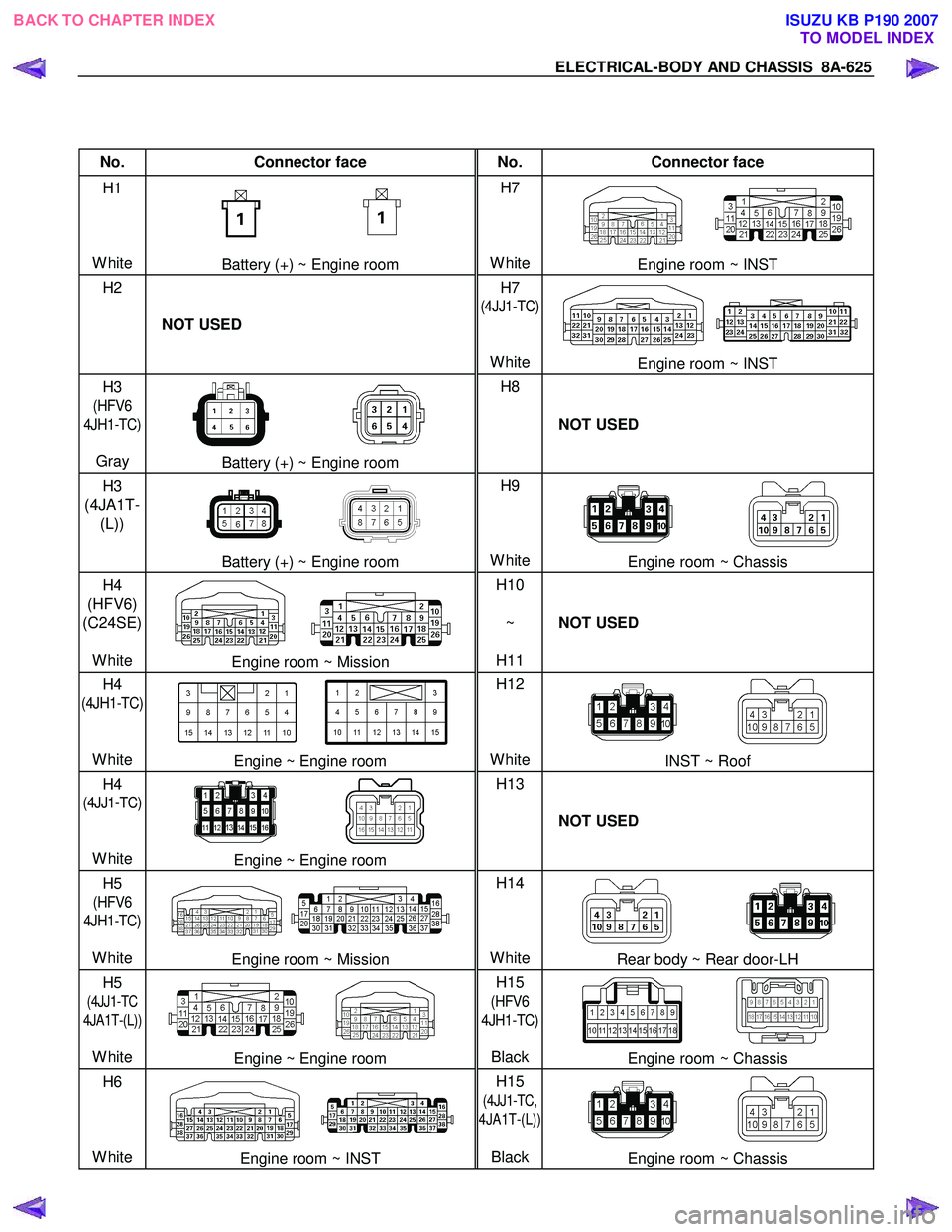
No. Connector face No. Connector face
H1
White
Battery (+) ~ Engine room H7
WhiteEngine room ~ INST
H2
NOT USED H7
(4JJ1-TC)
White
Engine room ~ INST
H3
(HFV6
4JH1-TC)
Gray
Battery (+) ~ Engine room H8
NOT USED
H3
(4JA1T- (L))
Battery (+) ~ Engine room H9
WhiteEngine room ~ Chassis
H4
(HFV6)
(C24SE)
White
Engine room ~ Mission H10
~
H11 NOT USED
H4
(4JH1-TC)
White
Engine ~ Engine room H12
WhiteINST ~ Roof
H4
(4JJ1-TC)
White
Engine ~ Engine room H13
NOT USED
H5
(HFV6
4JH1-TC)
White
Engine room ~ Mission H14
WhiteRear body ~ Rear door-LH
H5
(4JJ1-TC
4JA1T-(L))
White
Engine ~ Engine room H15
(HFV6
4JH1-TC)
Black
Engine room ~ Chassis
H6
White
Engine room ~ INST H15
(4JJ1-TC,
4JA1T-(L))
Black
Engine room ~ Chassis
BACK TO CHAPTER INDEX TO MODEL INDEXISUZU KB P190 2007
Page 5564 of 6020
8A-626 ELECTRICAL-BODY AND CHASSIS
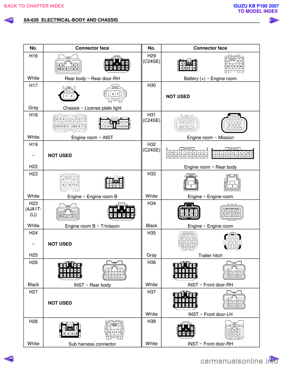
No. Connector face No. Connector face
H16
White
Rear body ~ Rear door-RH H29
(C24SE)
Battery (+) ~ Engine room
H17
Gray
Chassis ~ License plate light H30
NOT USED
H18
White
Engine room ~ INST H31
(C24SE)
Engine room ~ Mission
H19
~
H22 NOT USED H32
(C24SE)
Engine room ~ Rear body
H23
White
Engine ~ Engine room B H33
WhiteEngine ~ Engine room
H23
(4JA1T- (L))
White
Engine room B ~ T/misson H34
BlackEngine ~ Engine room
H24
~
H25 NOT USED H35
Gray
Trailer hitch
H26
Black
INST ~ Rear body H36
WhiteINST ~ Front door-RH
H27
NOT USED H37
White
INST ~ Front door-LH
H28
White
Sub harness connector H38
WhiteINST ~ Front door-RH
BACK TO CHAPTER INDEX TO MODEL INDEXISUZU KB P190 2007
Page 5565 of 6020
ELECTRICAL-BODY AND CHASSIS 8A-627
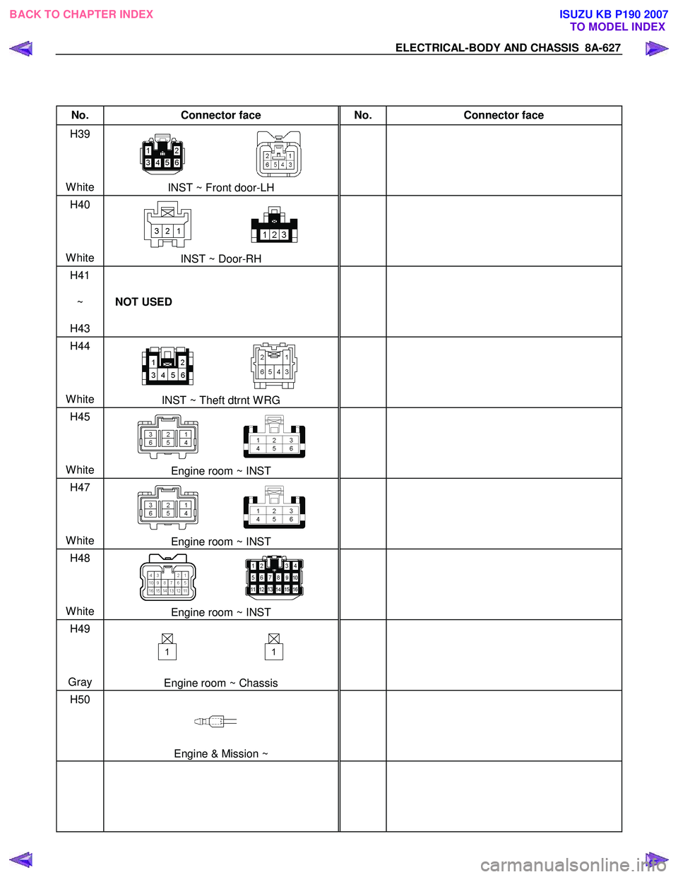
No. Connector face No. Connector face
H39
White
INST ~ Front door-LH
H40
White
INST ~ Door-RH
H41
~
H43 NOT USED
H44
White
INST ~ Theft dtrnt W RG
H45
White
Engine room ~ INST
H47
White
Engine room ~ INST
H48
White
Engine room ~ INST
H49
Gray
Engine room ~ Chassis
H50
Engine & Mission ~
BACK TO CHAPTER INDEX
TO MODEL INDEXISUZU KB P190 2007
Page 5568 of 6020
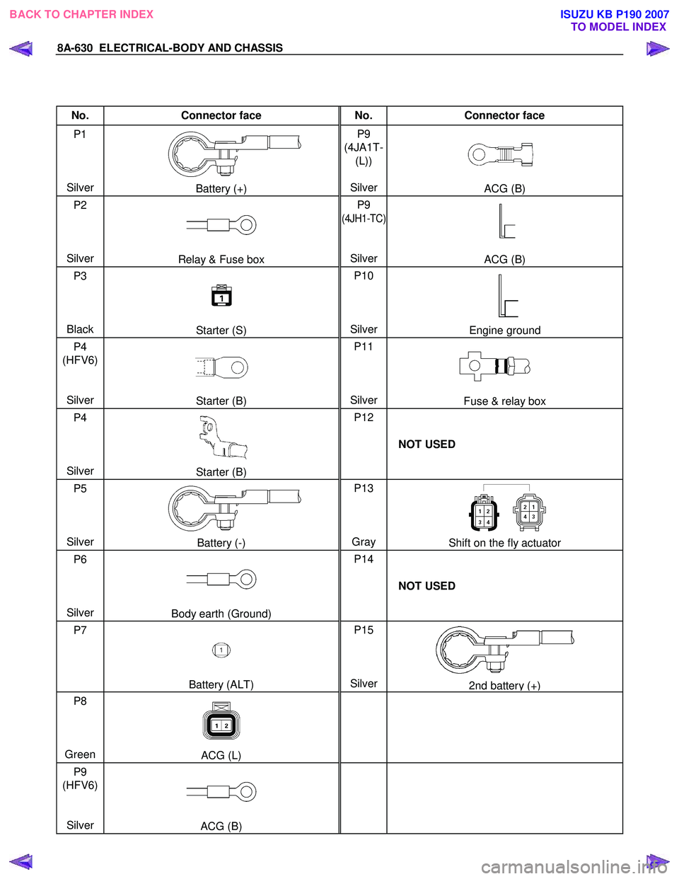
8A-630 ELECTRICAL-BODY AND CHASSIS
No. Connector face No. Connector face
P1
Silver
Battery (+) P9
(4JA1T- (L))
SilverACG (B)
P2
Silver
Relay & Fuse box P9
(4JH1-TC)
Silver
ACG (B)
P3
Black
Starter (S) P10
SilverEngine ground
P4
(HFV6)
Silver
Starter (B) P11
SilverFuse & relay box
P4
Silver
Starter (B) P12
NOT USED
P5
Silver
Battery (-) P13
Gray Shift on the fly actuator
P6
Silver
Body earth (Ground) P14
NOT USED
P7
Battery (ALT) P15
Silver2nd battery (+)
P8
Green
ACG (L)
P9
(HFV6)
Silver
ACG (B)
BACK TO CHAPTER INDEX
TO MODEL INDEXISUZU KB P190 2007
Page 5574 of 6020
8B-2 CRUISE CONTROL SYSTEM
General Description
The cruise control keeps the vehicle running at a fixed speed until a signal canceling this fixed speed is received.
W hen the main switch “AUTO CRUISE” is turned on with the vehicle in the running mode, the battery voltage is
applied to the control unit (Engine control module). W hen a signal from the control unit while the vehicle is in this
state, the cruise control actuator is activated to operate the system. Also, while the system is operating, the cruise
control set indicator light in the meter assembly lights up.
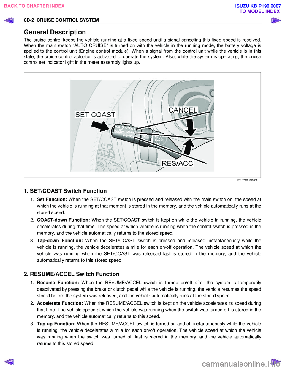
RTU7Z0SH019601
1. SET/COAST Switch Function
1. Set Function: W hen the SET/COAST switch is pressed and released with the main switch on, the speed at
which the vehicle is running at that moment is stored in the memory, and the vehicle automatically runs at the
stored speed.
2. COAST-down Function: W hen the SET/COAST switch is kept on while the vehicle in running, the vehicle
decelerates during that time. The speed at which vehicle is running when the control switch is pressed in the
memory, and the vehicle automatically returns to the stored speed.
3. Tap-down Function: W hen the SET/COAST switch is pressed and released instantaneously while the
vehicle is running, the vehicle decelerates a mile for each on/off operation. The vehicle speed at which the
vehicle was running when the SET/COAST was released last is stored in the memory, and the vehicle
automatically returns to this stored speed.
2. RESUME/ACCEL Switch Function
1. Resume Function: W hen the RESUME/ACCEL switch is turned on/off after the system is temporarily
deactivated by pressing the brake or clutch pedal while the vehicle is running, the vehicle resumes the speed
stored before the system was released, and the vehicle automatically runs at the stored speed.
2. Accelerate Function: W hen the RESUME/ACCEL switch is kept on the vehicle accelerates its speed during
that time. The vehicle speed at which the vehicle was running when the switch was turned off is stored in the
memory, and the vehicle automatically returns to this speed.
3. Tap-up Function: W hen the RESUME/ACCEL switch is turned on and off instantaneously while the vehicle
is running, the vehicle decelerates a mile for each on/off operation. The vehicle speed at which the vehicle
was running when the switch was turned off last is stored in the memory, and the vehicle automatically
returns to this stored speed.
BACK TO CHAPTER INDEX TO MODEL INDEXISUZU KB P190 2007
Page 5579 of 6020
Cruise Control – HFV6 Page 8C–1
8C
Cruise Control – HFV6
ATTENTION
Before performing any Service Operation or other procedure described in this Section, refer to General Information Warnings, Cautions and Notes for correct workshop practices with regard to safety and/or property damage.
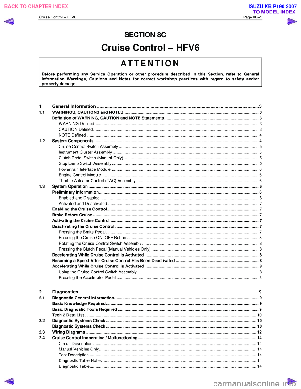
1 General Information ...............................................................................................................................3
1.1 WARNINGS, CAUTIONS and NOTES................................................................................................... ................. 3
Definition of WARNING, CAUTION and NOTE Statements ............................................................................. .... 3
WARNING Defined............................................................................................................................................. 3
CAUTION Defined .............................................................................................................................................. 3
NOTE Defined .................................................................................................................................................... 4
1.2 System Components .............................................................................................................. ............................... 4
Cruise Control Switch Assembly ................................................................................................. ....................... 5
Instrument Cluster Assembly ............................................................................................................................. 5
Clutch Pedal Switch (Manual Only) .............................................................................................. ...................... 5
Stop Lamp Switch Assembly .............................................................................................................................. 5
Powertrain Interface Module .............................................................................................................................. 6
Engine Control Module ....................................................................................................................................... 6
Throttle Actuator Control (TAC) Assembly ....................................................................................... .................. 6
1.3 System Operation .................................................................................................................................................. 6
Preliminary Information......................................................................................................................................... 6
Enabled and Disabled ........................................................................................................... ............................. 6
Activated and Deactivated...................................................................................................... ............................ 7
Enabling the Cruise Control.................................................................................................... .............................. 7
Brake Before Cruise .............................................................................................................................................. 7
Activating the Cruise Control .................................................................................................. ............................. 7
Deactivating the Cruise Control ................................................................................................ ........................... 7
Pressing the Brake Pedal ................................................................................................................................... 7
Pressing the Cruise ON–OFF Button .............................................................................................. ................... 8
Rotating the Cruise Control Switch Assembly .................................................................................... ................ 8
Pressing the Clutch Pedal (Manual Vehicles Only) ............................................................................... ............. 8
Decelerating While Cruise Control is Activated ................................................................................. ................. 8
Resuming a Speed After Cruise Control Has Been Deactivated ..................................................................... .. 8
Accelerating While Cruise Control is Activated .................................................................................................. 8
Using the Cruise Control Switch Assembly ........................................................................................................ 8
Pressing the Accelerator Pedal .......................................................................................................................... 8
2 Diagnostics .............................................................................................................................................9
2.1 Diagnostic General Information............................................................................................................................ 9
Basic Knowledge Required ................................................................................................................................... 9
Basic Diagnostic Tools Required ......................................................................................................................... 9
Tech 2 Data List ................................................................................................................................................... 10
2.2 Diagnostic Systems Check ....................................................................................................... .......................... 10
Diagnostic Systems Check ................................................................................................................................. 10
2.3 Wiring Diagrams .................................................................................................................................................. 12
2.4 Cruise Control Inoperative / Malfunctioning.................................................................................... .................. 14
Circuit Description ............................................................................................................................................ 14
Manual Vehicles Only........................................................................................................... ............................ 14
Test Description ............................................................................................................................................... 14
Diagnostic Table Notes ......................................................................................................... ........................... 14
Diagnostic Table............................................................................................................................................... 14
SECTION
BACK TO CHAPTER INDEX
TO MODEL INDEX
ISUZU KB P190 2007
Page 5581 of 6020
Cruise Control – HFV6 Page 8C–3
1 General Information
A new cruise control system has been introduced due to changes in the powertrain architecture and components. There
is no longer a cruise control module; instead the management has been taken over by the engine control module (ECM).
To the user, the system operates as previously, with all controls from the cruise control switch assembly and the cruise
control messages presented by the instrument cluster. For vehicles fitted with the HFV6 engine refer to 1.3 System
Operation .
The cruise control system now has an
additional fail-safe feature. The brake pedal
must be pressed in the ignition cycle for the
cruise control to be engaged. The cruise
control will not engage until this is done.
1.1 WARNINGS, CAUTIONS and NOTES
This Section contains various W ARNINGS, CAUTIONS and NOTE statements that you must observe carefully to reduce
the risk of death or injury during service, repair procedures or vehicle operation. Incorrect service or repair procedures
may damage the vehicle or cause operational faults. W ARNINGS, CAUTION and NOTE statements are not exhaustive.
GM HOLDEN LTD can not possibly warn of all the potentially hazardous consequences of failure to follow these
instructions.
Definition of WARNING, CAUTION and NOTE Statements
Diagnosis and repair procedures in this Section contain both general and specific W ARNING, CAUTION and NOTE
statements. GM HOLDEN LTD is dedicated to the presentation of service information that helps the technician to
diagnose and repair the systems necessary for proper operation of the vehicle. Certain procedures may present a hazard
to the technician if they are not followed in the recommended manner. W ARNING, CAUTION and NOTE statements are
designed to help prevent these hazards from occurring, but not all hazards can be foreseen.
WARNING Defined
A W ARNING statement immediately precedes an operating procedure or maintenance practice which, if not correctly
followed, could result in death or injury. A WARNING statement alerts you to take necessary action or not to take a
prohibited action. If a W ARNING statement is ignored, the following consequences may occur:
• Death or injury to the technician or other personnel working on the vehicle,
• Death or injury to other people in or near the workplace area, and / or
• Death or injury to the driver / or passenger(s) of the vehicle or other people, if the vehicle has been improperly
repaired.
CAUTION Defined
A CAUTION statement immediately precedes an operating procedure or maintenance practice which, if not correctly
followed, could result in damage to or destruction of equipment, or corruption of data. If a CAUTION statement is ignored,
the following consequences may occur:
• Damage to the vehicle,
• Unnecessary vehicle repairs or component replacement,
• Faulty operation or performance of any system or component being repaired,
• Damage to any system or components which depend on the proper operation of the system or component being
repaired,
• Faulty operation or performance of any systems or components which depend on the proper operation or
performance of the system or component under repair,
• Damage to fasteners, basic tools or special tools and / or
• Leakage of coolant, lubricant or other vital fluids.
BACK TO CHAPTER INDEX
TO MODEL INDEXISUZU KB P190 2007