Page 5597 of 6020

Cruise Control – HFV6 Page 8C–19
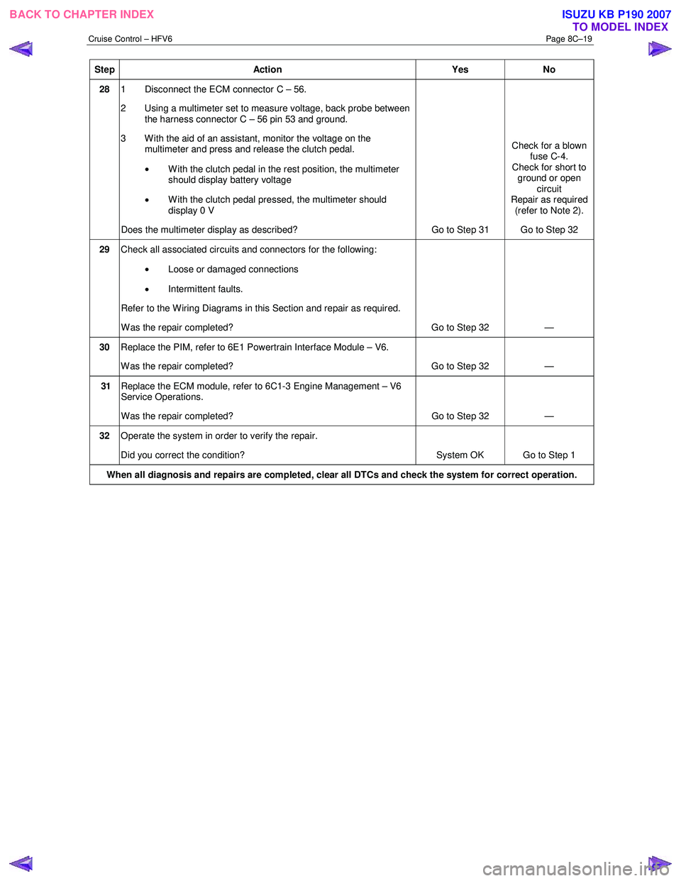
Step Action Yes No
28 1 Disconnect the ECM connector C – 56.
2 Using a multimeter set to measure voltage, back probe between the harness connector C – 56 pin 53 and ground.
3 W ith the aid of an assistant, monitor the voltage on the multimeter and press and release the clutch pedal.
• With the clutch pedal in the rest position, the multimeter
should display battery voltage
• W ith the clutch pedal pressed, the multimeter should
display 0 V
Does the multimeter display as described? Go to Step 31 Check for a blown
fuse C-4.
Check for short to ground or open circuit
Repair as required (refer to Note 2).
Go to Step 32
29 Check all associated circuits and connectors for the following:
• Loose or damaged connections
• Intermittent faults.
Refer to the Wiring Diagrams in this Section and repair as required.
W as the repair completed? Go to Step 32 —
30 Replace the PIM, refer to 6E1 Powertrain Interface Module – V6.
W as the repair completed? Go to Step 32 —
31 Replace the ECM module, refer to 6C1-3 Engine Management – V6
Service Operations.
W as the repair completed? Go to Step 32 —
32 Operate the system in order to verify the repair.
Did you correct the condition? System OK Go to Step 1
When all diagnosis and repairs are completed, clear all DTCs and check the system for correct operation.
BACK TO CHAPTER INDEX
TO MODEL INDEXISUZU KB P190 2007
Page 5627 of 6020
9-22 ACCESSORIES
CONNECTOR LIST
No. Connector face No. Connector face
B-10
White
Clock B-64
SilverW eld splice 1 (Illumination)
B-14
Gray
Audio B-65
SilverW eld splice 2 (Ground)
B-20
White
Cigar lighter illumination B-88
SilverW eld splice 5
B-21
White
Cigar lighter C-2
SilverEngine room –RH ground
B-22
Black
Cigar lighter C-108
White
J/B E1
B-41
White
Acc socket D-3
BlackFront speaker -RH
B-42
White
Acc socket D-8
BlackFront speaker -LH
B-55
White
J/B I3 D-13
BlackRear speaker -LH
B-56
White
J/B I4 D-17
BlackRear speaker -RH
B-62
White
Ignition switch (IGSUB: G1) D-21
WhiteTweeter -RH
BACK TO CHAPTER INDEX TO MODEL INDEXISUZU KB P190 2007
Page 5628 of 6020
ACCESSORIES 9-23
No. Connector face No. Connector face
D-22
White
Tweeter -LH P-1
SilverBattery (+)
H-14
White
Rear body ∼ Rear door -LH P-2
SilverRelay & Fuse box
H-16
White
Rear body ∼ Rear door -RH P-5
SilverBattery (-)
H-18
White
Engine room ∼ INST P-6
SilverBody earth
H-36
White
INST ~ Front door-RH P-10
SilverEngine ground
H-37
White
INST ~ Front door-LH R-7
BlackRear speaker -LH
H-39
White
INST ~ Front door-LH R-8
BlackRear speaker -RH
H-42
White
INST ~ Front door-driver
H-43
INST ~ Body
H-43
White
INST ~ Body
BACK TO CHAPTER INDEX TO MODEL INDEXISUZU KB P190 2007
Page 5651 of 6020

9A-16 SUPPLEMENTAL RESTRAINT SYSTEM
RTW 79ASH000201
Seat Belt with Pretensioner (If so
equipped)
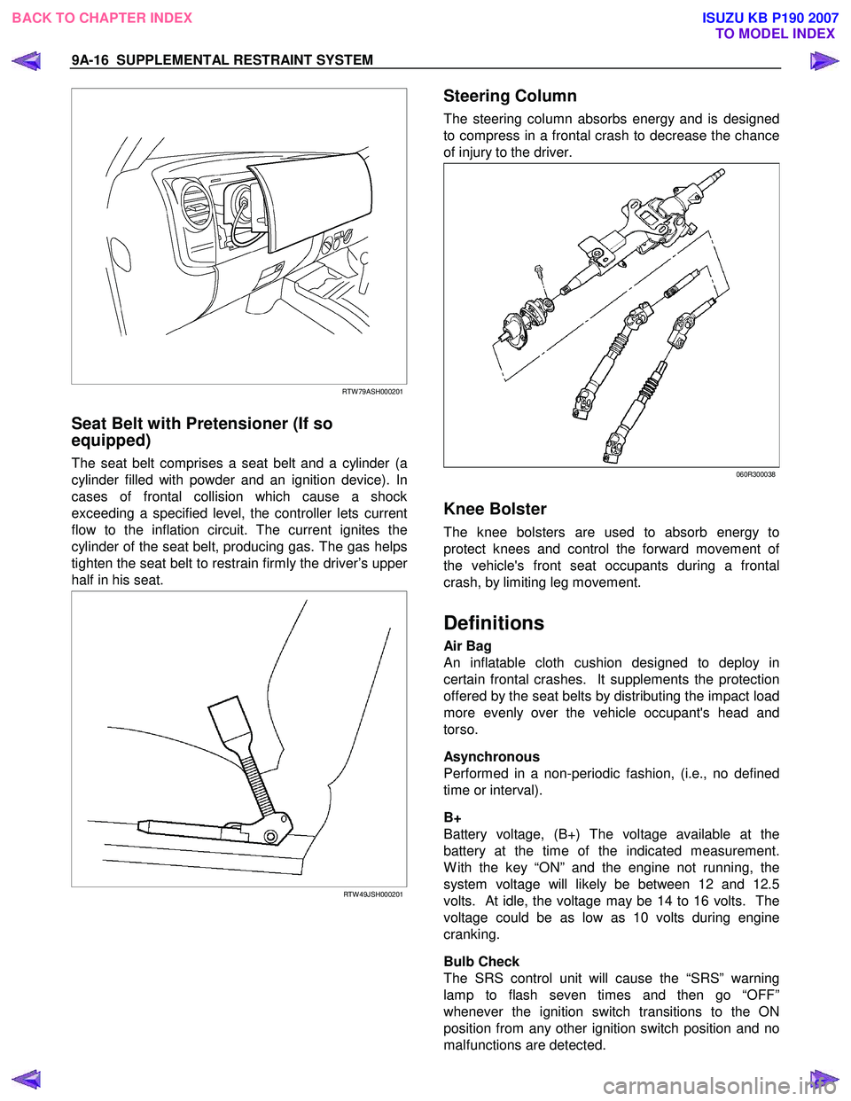
The seat belt comprises a seat belt and a cylinder (a
cylinder filled with powder and an ignition device). In
cases of frontal collision which cause a shock
exceeding a specified level, the controller lets current
flow to the inflation circuit. The current ignites the
cylinder of the seat belt, producing gas. The gas helps
tighten the seat belt to restrain firmly the driver’s uppe
r
half in his seat.
RTW 49JSH000201
Steering Column
The steering column absorbs energy and is designed
to compress in a frontal crash to decrease the chance
of injury to the driver.
060R300038
Knee Bolster
The knee bolsters are used to absorb energy to
protect knees and control the forward movement o
f
the vehicle's front seat occupants during a frontal
crash, by limiting leg movement.
Definitions
Air Bag
An inflatable cloth cushion designed to deploy in
certain frontal crashes. It supplements the protection
offered by the seat belts by distributing the impact load
more evenly over the vehicle occupant's head and
torso.
Asynchronous
Performed in a non-periodic fashion, (i.e., no defined
time or interval).
B+
Battery voltage, (B+) The voltage available at the
battery at the time of the indicated measurement.
W ith the key “ON” and the engine not running, the
system voltage will likely be between 12 and 12.5
volts. At idle, the voltage may be 14 to 16 volts. The
voltage could be as low as 10 volts during engine
cranking.
Bulb Check
The SRS control unit will cause the “SRS” warning
lamp to flash seven times and then go “OFF”
whenever the ignition switch transitions to the ON
position from any other ignition switch position and no
malfunctions are detected.
BACK TO CHAPTER INDEX TO MODEL INDEXISUZU KB P190 2007
Page 5754 of 6020
9A1-72 RESTRAINT CONTROL SYSTEM
DTC B0062 (Flash Code 62) Battery Voltage Too High
Step Action Yes No
1 W as the “SRS Diagnostic System Check” performed? Go to Step 2 Go to the “SRS
Diagnostic System Check”
2 1. Ignition switch is at “LOCK”.
2. Disconnect the SRS control unit.
3. Ignition switch “ON”.
4. Measure voltage on SRS control unit harness connector from terminal “1” to terminal “3” (ground).
Is voltage on terminal “1” below 16.5V? Ignition switch is at
“LOCK”.
Replace the SRS control unit.
Go to Step 3 Inspect the
Charging System. Refer to the
"Engine Electrical" section.
Go to Step 3
3 1. Reconnect all the components and ensure all components
are properly mounted.
2. Clear diagnostic trouble codes.
Is this step finished? Go to the “SRS
Diagnostic system Check” ―
BACK TO CHAPTER INDEX
TO MODEL INDEX
ISUZU KB P190 2007
Page 5756 of 6020

9A1-74 RESTRAINT CONTROL SYSTEM
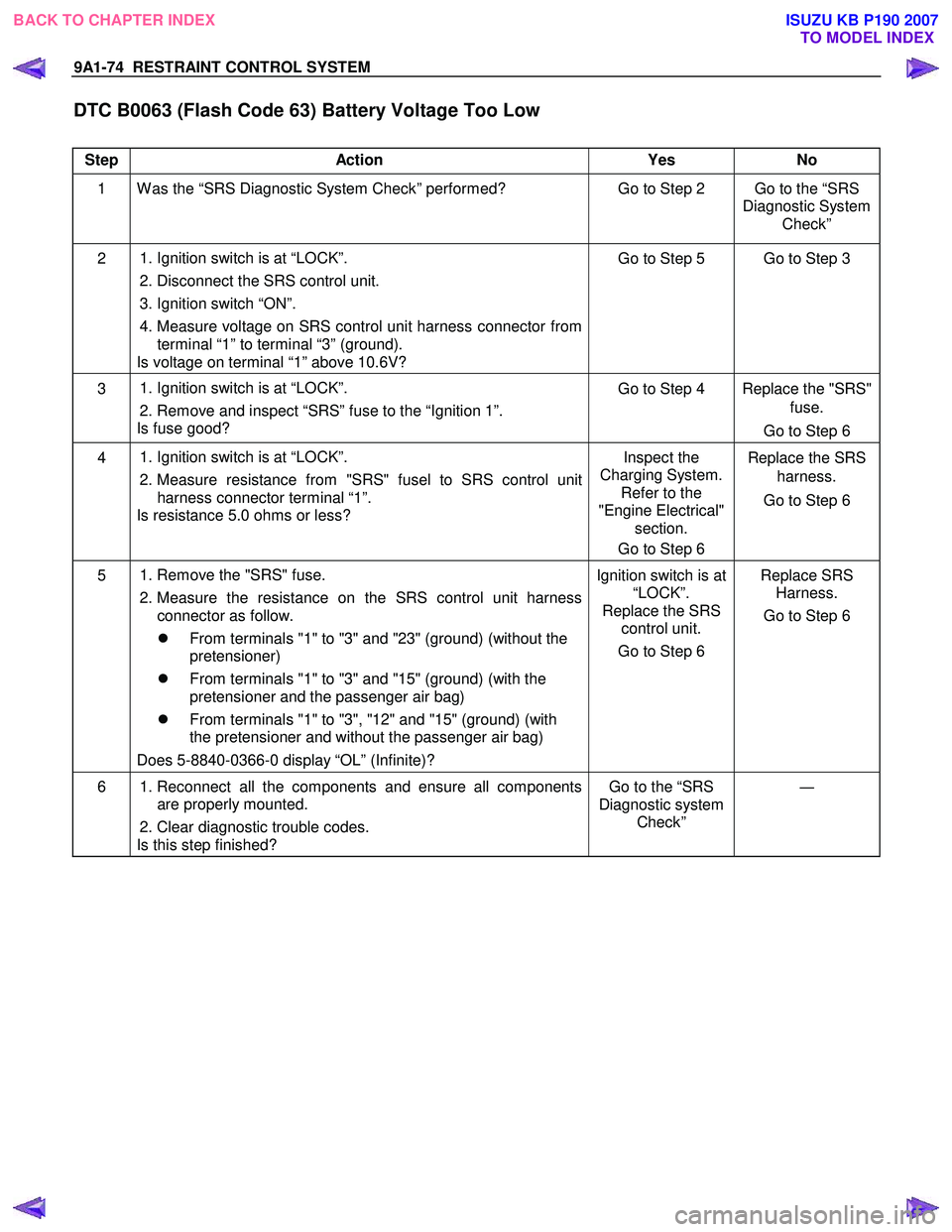
DTC B0063 (Flash Code 63) Battery Voltage Too Low
Step Action Yes No
1 W as the “SRS Diagnostic System Check” performed? Go to Step 2 Go to the “SRS
Diagnostic System Check”
2 1. Ignition switch is at “LOCK”.
2. Disconnect the SRS control unit.
3. Ignition switch “ON”.
4. Measure voltage on SRS control unit harness connector from terminal “1” to terminal “3” (ground).
Is voltage on terminal “1” above 10.6V? Go to Step 5 Go to Step 3
3
1. Ignition switch is at “LOCK”.
2. Remove and inspect “SRS” fuse to the “Ignition 1”.
Is fuse good? Go to Step 4 Replace the "SRS"
fuse.
Go to Step 6
4
1. Ignition switch is at “LOCK”.
2. Measure resistance from "SRS" fusel to SRS control unit
harness connector terminal “1”.
Is resistance 5.0 ohms or less? Inspect the
Charging System. Refer to the
"Engine Electrical" section.
Go to Step 6 Replace the SRS
harness.
Go to Step 6
5
1. Remove the "SRS" fuse.
2. Measure the resistance on the SRS control unit harness connector as follow.
�z From terminals "1" to "3" and "23" (ground) (without the
pretensioner)
�z From terminals "1" to "3" and "15" (ground) (with the
pretensioner and the passenger air bag)
�z From terminals "1" to "3", "12" and "15" (ground) (with
the pretensioner and without the passenger air bag)
Does 5-8840-0366-0 display “OL” (Infinite)? Ignition switch is at
“LOCK”.
Replace the SRS control unit.
Go to Step 6 Replace SRS
Harness.
Go to Step 6
6 1. Reconnect all the components and ensure all components
are properly mounted.
2. Clear diagnostic trouble codes.
Is this step finished? Go to the “SRS
Diagnostic system Check” ―
BACK TO CHAPTER INDEX
TO MODEL INDEX
ISUZU KB P190 2007
Page 5760 of 6020
10-2 CAB
WINDSHIELD
REMOVAL AND INSTALLATION
This illustration is based on RHD model
RTW 7A0LF001201
Removal Steps
1. Interior trim panels (Front side) /Headlining/Instrument panel assembly
2. W iper arm assembly
▲ 3. Room mirror
4. Side molding
5. Vent cowl cover
6. W indshield stopper
7. Upper molding
▲ 8. W indshield
9. Engine hood rear seal
Installation Steps
▲
9. Engine hood rear seal
▲ 8. W indshield
7. Upper molding
6. W indshield stopper
5. Vent cowl cover
4. Side molding
3. Room mirror
▲ 2. W iper arm assembly
1. Interior trim panels (Front side) /Headlining/Instrument panel assembly
BACK TO CHAPTER INDEX TO MODEL INDEX
ISUZU KB P190 2007
Page 5761 of 6020

CAB 10-3
RUW 5A0SH002901
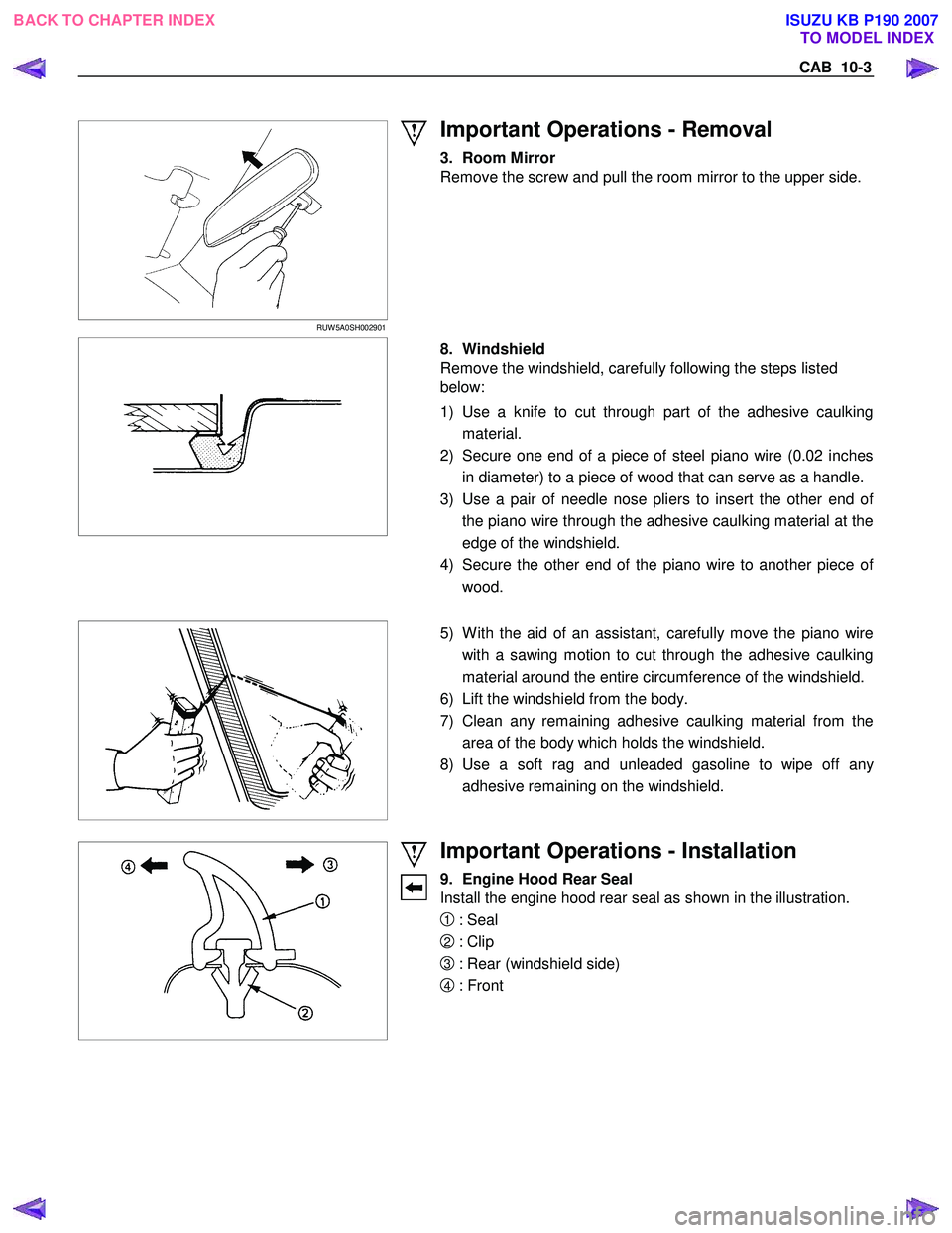
Important Operations - Removal
3. Room Mirror
Remove the screw and pull the room mirror to the upper side.
8. Windshield
Remove the windshield, carefully following the steps listed
below:
1) Use a knife to cut through part of the adhesive caulking material.
2) Secure one end of a piece of steel piano wire (0.02 inches in diameter) to a piece of wood that can serve as a handle.
3) Use a pair of needle nose pliers to insert the other end o
f
the piano wire through the adhesive caulking material at the
edge of the windshield.
4) Secure the other end of the piano wire to another piece o
f
wood.
5) W ith the aid of an assistant, carefully move the piano wire
with a sawing motion to cut through the adhesive caulking
material around the entire circumference of the windshield.
6) Lift the windshield from the body.
7) Clean any remaining adhesive caulking material from the area of the body which holds the windshield.
8) Use a soft rag and unleaded gasoline to wipe off an
y
adhesive remaining on the windshield.
Important Operations - Installation
9. Engine Hood Rear Seal
Install the engine hood rear seal as shown in the illustration.
1 : Seal
2 : Clip
3 : Rear (windshield side)
4 : Front
BACK TO CHAPTER INDEX TO MODEL INDEX
ISUZU KB P190 2007