Page 1651 of 6020
6E-34 ENGINE CONTROL SYSTEM (4JK1/4JJ1)
Engine Control Connector End Views
Accelerator Pedal Position (APP) SensorBarometric Pressure (BARO) Sensor
Boost Pressure Sensor
Connector No. C-40
Connector Color Black
Test Adapter No. J-35616-64A
Pin No. Wire Color Pin Function
1 BLU APP sensor 3 5V reference
2 — Not used
3 ORN/ BLU APP sensor 2 low reference
4 BLK APP sensor 1 low reference
5 RED APP sensor 1 signal
6 BLU/ WHT APP sensor 3 signal
7 BLU/ RED APP sensor 3 low reference
8 ORN APP sensor 2 5V reference
9 BLU/ GRN APP sensor 2 signal
10 WHT APP sensor 1 5V reference
RTW76ESH001001
12345
678910
Connector No. E-40
Connector Color Gray
Test Adapter No. J-35616-64A
Pin No. Wire Color Pin Function
1 ORN Sensor low reference
2 PNK/ GRN Sensor signal
3 BLU/ GRN Sensor 5V reference
RTW76ESH000901
3
12
LNW46ESH001501
12 3
BACK TO CHAPTER INDEX
TO MODEL INDEX
ISUZU KB P190 2007
Page 1652 of 6020
ENGINE CONTROL SYSTEM (4JK1/4JJ1) 6E-35
Brake SwitchClutch Switch
Camshaft Position (CMP) Sensor
Connector No.
E-107
Connector Color Black
Test Adapter No. J-35616-64A
Pin No. Wire Color Pin Function
1 YEL Sensor signal
2 BLU Sensor low reference
3 GRN Sensor 5V reference
Connector No. C-44
Connector Color White
Test Adapter No. J-35616-40 (Pin1-2)
J-35616-2A (Pin3-4)
Pin No. Wire Color Pin Function
1GRN Switch 1 (stop lamp switch)
battery voltage feed
2 RED Switch 1 (stop lamp switch) signal
3 ORN Switch 2 signal
4WHT/ GRN Brake switch 2 ignition voltage
feed
RTW76ESH000801
12
34Connector No. C-77
Connector Color White
Test Adapter No. J-35616-42
Pin No. Wire Color Pin Function
1 WHT/ GRN Ignition voltage feed
2 YEL Switch signal
LNW46ESH000801
1
2
RTW76ESH000701
123
BACK TO CHAPTER INDEX
TO MODEL INDEX
ISUZU KB P190 2007
Page 1653 of 6020
6E-36 ENGINE CONTROL SYSTEM (4JK1/4JJ1)
Crankshaft Position (CKP) SensorCruise Main Switch
Data Link Connector (DLC)
Connector No.
E-39
Connector Color Black
Test Adapter No. J-35616-64A
Pin No. Wire Color Pin Function
1 WHT Sensor signal
2 BLK Sensor low reference
3 RED Sensor 5V reference
Connector No. E-52
Connector Color Black
Test Adapter No. J-35616-64A
Pin No. Wire Color Pin Function
1 YEL Sensor signal
2 BLU Sensor low reference
3 GRN Sensor 5V reference
RTW76ESH000701
123
Connector No. B-67
Connector Color White
Test Adapter No. J-35616-33
Pin No. Wire Color Pin Function
1 RED/ GRN Illumination lamp ground
2 GRN/ RED Illumination lamp voltage feed
3 WHT/ GRN Cruise main switch signal
4WHT/ GRN Cruise main switch ignition
voltage
5 — Not used
6 GRN/ WHT Cruise main switch ignition lamp
ground
RTW76ESH001101
123456
LNW36ESH015801
87654321
16151413121110
9
BACK TO CHAPTER INDEX
TO MODEL INDEX
ISUZU KB P190 2007
Page 1654 of 6020

ENGINE CONTROL SYSTEM (4JK1/4JJ1) 6E-37
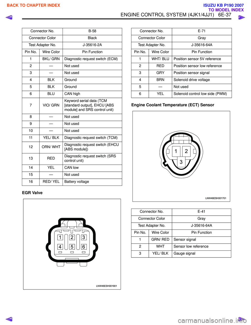
EGR ValveEngine Coolant Temperature (ECT) Sensor
Connector No.
B-58
Connector Color Black
Test Adapter No. J-35616-2A
Pin No. Wire Color Pin Function
1 BKL/ GRN Diagnostic request switch (ECM)
2 — Not used
3 — Not used
4 BLK Ground
5 BLK Ground
6 BLU CAN high
7 VIO/ GRN Keyword serial data (TCM
[standard output], EHCU [ABS
module] and SRS control unit)
8 — Not used
9 — Not used
10 — Not used 11 YEL/ BLK Diagnostic request switch (TCM)
12 ORN/ WHT Diagnostic request switch (EHCU
[ABS module])
13 RED Diagnostic request switch (SRS
control unit)
14 YEL CAN low
15 — Not used
16 RED/ YEL Battery voltage
LNW46ESH001901
1
4 2
5 3
6
Connector No. E-71
Connector Color Gray
Test Adapter No. J-35616-64A
Pin No. Wire Color Pin Function
1 WHT/ BLU Position sensor 5V reference
2 RED Position sensor low reference
3 GRY Position sensor signal
4 BRN Solenoid drive voltage
5—Not used
6 YEL Solenoid control low side (PWM)
Connector No. E-41
Connector Color Gray
Test Adapter No. J-35616-64A
Pin No. Wire Color Pin Function
1 GRN/ RED Sensor signal
2 WHT Sensor low reference
3 YEL/ BLK Gauge signal
LNW46ESH001701
12
3
BACK TO CHAPTER INDEX
TO MODEL INDEX
ISUZU KB P190 2007
Page 1657 of 6020
6E-40 ENGINE CONTROL SYSTEM (4JK1/4JJ1)
Fuel Rail Pressure (FRP) Sensor
Fuel Temperature (FT) Sensor Glow Plug
Mass Air Flow (MAF)/ Intake Air Temperature (IAT)
Sensor
Connector No. E-48
Connector Color Black
Test Adapter No. J-35616-64A
Pin No. Wire Color Pin Function
1 BLK Sensor low reference
2 WHT Sensor signal
3 RED Sensor 5V reference
LNW46ESH001501
12 3
LNW46ESH001201
12
Connector No. E-27
Connector Color Gray
Test Adapter No. J-35616-64A
Pin No. Wire Color Pin Function
1 YEL/ RED Sensor low reference
2 PNK Sensor signal
Connector No. E-49
Connector Color Silver
Pin No. Wire Color Pin Function 1 BLK/ RED Power supply
LNW46ESH000701
LNW46ESH001801
12345
BACK TO CHAPTER INDEX
TO MODEL INDEX
ISUZU KB P190 2007
Page 1658 of 6020
ENGINE CONTROL SYSTEM (4JK1/4JJ1) 6E-41
Intake Throttle ValveSwirl Control Solenoid Valve
Turbocharger Nozzle Control Solenoid Valve
Connector No. E-47
Connector Color Black
Test Adapter No. J-35616-64A
Pin No. Wire Color Pin Function
1 RED/ BLU MAF sensor ignition voltage feed
2 WHT/ BLU MAF sensor low reference
3 ORN/ BLU MAF sensor signal
4 BLU/ RED IAT sensor signal
5 BLU/ GRN IAT sensor low reference
Connector No. E-38
Connector Color Black
Test Adapter No. J-35616-64A
Pin No. Wire Color Pin Function
1 RED Solenoid control low side (PWM)
2 WHT Solenoid drive voltage
3 BLU Position sensor low reference
4 — Not used
5 ORN Position sensor signal
6 GRY Position sensor 5V reference
RTW76ESH000401
456
123
Connector No. E-67
Connector Color Brown
Test Adapter No. J-35616-64A
Pin No. Wire Color Pin Function 1 YEL Solenoid valve control
2 RED/ BLU Ignition voltage feed
RTW76ESH000201
12
RTW76ESH000101
21
BACK TO CHAPTER INDEX
TO MODEL INDEX
ISUZU KB P190 2007
Page 1659 of 6020
6E-42 ENGINE CONTROL SYSTEM (4JK1/4JJ1)
Vehicle Speed Sensor (VSS)
Connector No.E-106
Connector Color Brown
Test Adapter No. J-35616-64A
Pin No. Wire Color Pin Function
1 YEL/ BLK Solenoid valve control (PWM)
2 RED/ BLU Ignition voltage feed
Connector No. E-44
Connector Color Gray
Test Adapter No. J-35616-64A
Pin No. Wire Color Pin Function
1 YEL Ignition voltage feed
2 GRN/ WHT Sensor low reference
3 BLK/ YEL Sensor signal
LNW46ESH001401
12 3
BACK TO CHAPTER INDEX
TO MODEL INDEX
ISUZU KB P190 2007
Page 1662 of 6020

ENGINE CONTROL SYSTEM (4JK1/4JJ1) 6E-45
Diagnostic System Check - Engine Controls
Description
The Diagnostic System Check - Engine Controls is an
organized approach to identifying a condition that is
created by a malfunction in the electronic engine
control system. The Diagnostic System Check must be
the starting point for any driveability concern. The
Diagnostic System Check directs the service technician
to the next logical step in order to diagnose the
concern. Understanding and correctly using the
diagnostic table reduces diagnostic time, and prevents
the replacement of good parts.
Test Description
The numbers below refer to the step numbers on the
diagnostic table.
2. Lack of communication may be because of a partial
or a total malfunction of the serial data circuit.
7. The presence of DTCs which begin with U, indicate
that some other module is not communicating.
10. If there are other modules with DTCs set, refer to
the DTC list. The DTC list directs you to the appropriate
diagnostic procedure. If the control module stores
multiple DTCs, diagnose the DTCs in the following
order:
• Component level DTCs, such as sensor DTCs, solenoid DTCs, actuator DTCs, and relay DTCs.
Diagnose the multiple DTCs within this category in
numerical order. Begin with the lowest numbered
DTC, unless the diagnostic table directs you
otherwise. Diagnostic System Check Engine Controls
Important:
• DO NOT perform this diagnostic if there is not a driveability concern, unless another procedure
directs you to this diagnostic.
• Before you proceed with diagnosis, search for applicable service bulletins.
• Unless a diagnostic procedure instructs you, DO NOT clear the DTCs.
• If there is a condition with the starting system, refer to the starting system section in the engine
mechanical.
• Ensure the battery has a full charge.
• Ensure the battery cables (+) (-) are clean and tight.
• Ensure the ECM grounds are clean, tight, and in the correct location.
• Ensure the ECM harness connectors are clean and correctly connected. DO NOT attempt to
crank the engine with ECM harness connectors
disconnect.
• Ensure the ECM terminals are clean and correctly mating.
• Ensure the fuel injector ID code data is correctly programmed in to the ECM.
• Ensure the immobilizer security information is correctly programmed into the ECM and
immobilizer control unit (ICU).
• If there are fuel system DTC’s (P0087, P0088, P0089, P0093, P1093 or P1094), diagnose sensor
DTCs, solenoid DTCs, actuator DTCs and relay
DTCs first.
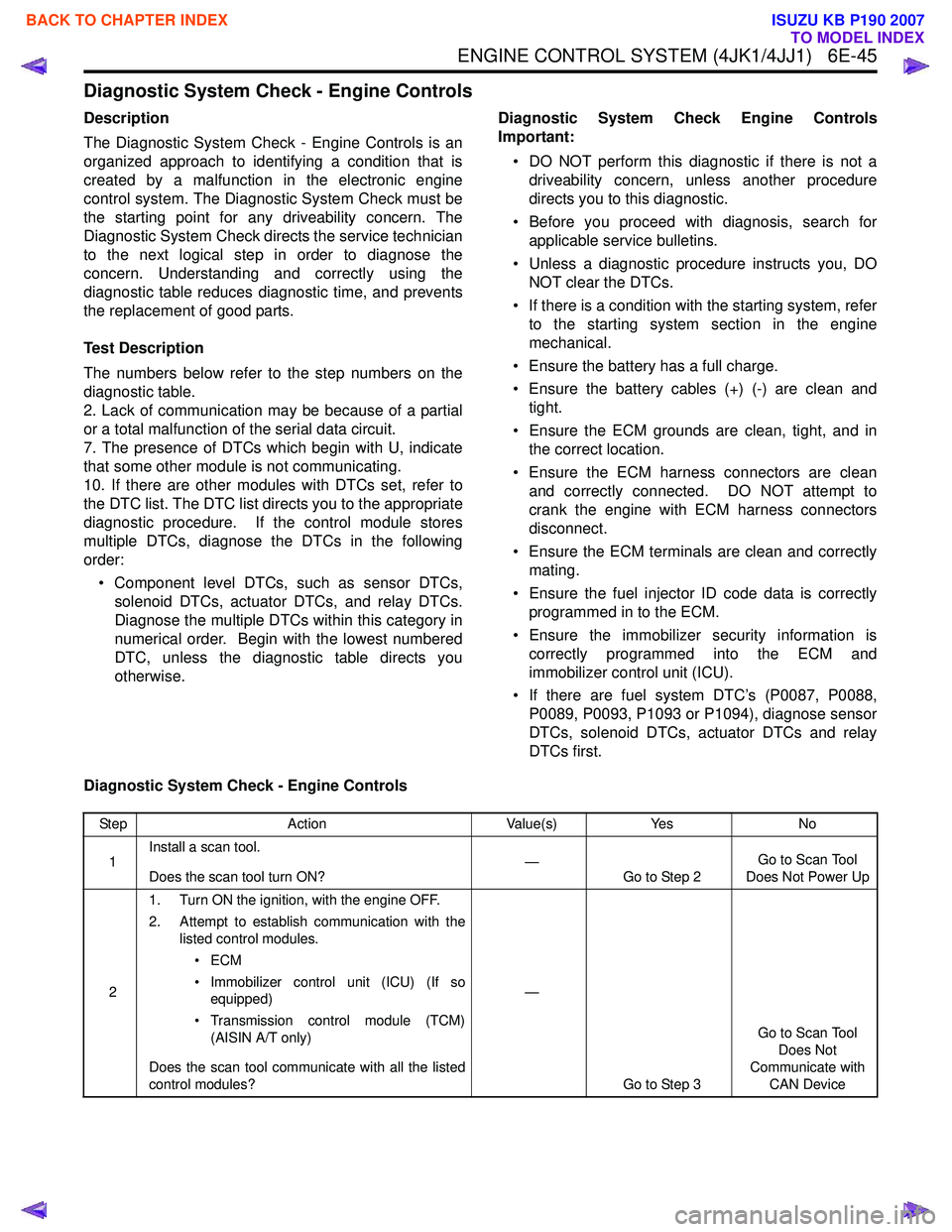
Diagnostic System Check - Engine Controls
Step Action Value(s)Yes No
1 Install a scan tool.
Does the scan tool turn ON? —
Go to Step 2 Go to Scan Tool
Does Not Power Up
2 1. Turn ON the ignition, with the engine OFF.
2. Attempt to establish communication with the listed control modules.
•ECM
• Immobilizer control unit (ICU) (If so equipped)
• Transmission control module (TCM) (AISIN A/T only)
Does the scan tool communicate with all the listed
control modules? —
Go to Step 3 Go to Scan Tool
Does Not
Communicate with CAN Device
BACK TO CHAPTER INDEX
TO MODEL INDEX
ISUZU KB P190 2007