2007 ISUZU KB P190 sensor
[x] Cancel search: sensorPage 1664 of 6020
ENGINE CONTROL SYSTEM (4JK1/4JJ1) 6E-47
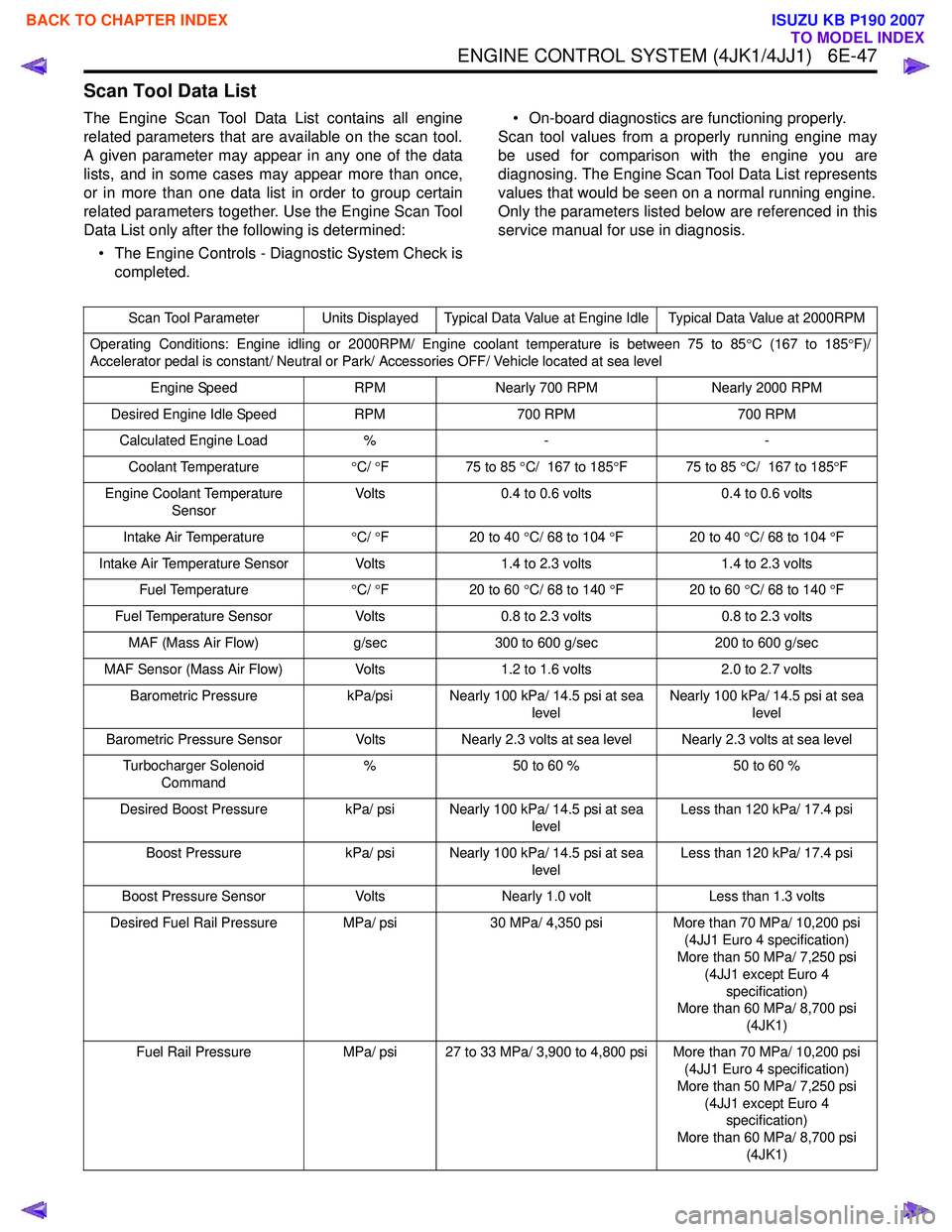
Scan Tool Data List
The Engine Scan Tool Data List contains all engine
related parameters that are available on the scan tool.
A given parameter may appear in any one of the data
lists, and in some cases may appear more than once,
or in more than one data list in order to group certain
related parameters together. Use the Engine Scan Tool
Data List only after the following is determined:
• The Engine Controls - Diagnostic System Check is completed. • On-board diagnostics are functioning properly.
Scan tool values from a properly running engine may
be used for comparison with the engine you are
diagnosing. The Engine Scan Tool Data List represents
values that would be seen on a normal running engine.
Only the parameters listed below are referenced in this
service manual for use in diagnosis.
Scan Tool Parameter Units Displayed Typical Data Value at Engine Idle Typical Data Value at 2000RPM
Operating Conditions: Engine idling or 2000RPM/ Engine coolant temperature is between 75 to 85 °C (167 to 185 °F)/
Accelerator pedal is constant/ Neutral or Park/ Accessories OFF/ Vehicle located at sea level
Engine Speed RPMNearly 700 RPM Nearly 2000 RPM
Desired Engine Idle Speed RPM700 RPM 700 RPM
Calculated Engine Load %- -
Coolant Temperature °C/ °F 75 to 85 °C/ 167 to 185 °F 75 to 85 °C/ 167 to 185 °F
Engine Coolant Temperature Sensor Volts
0.4 to 0.6 volts 0.4 to 0.6 volts
Intake Air Temperature °C/ °F 20 to 40 °C/ 68 to 104 °F 20 to 40 °C/ 68 to 104 °F
Intake Air Temperature Sensor Volts 1.4 to 2.3 volts1.4 to 2.3 volts
Fuel Temperature °C/ °F 20 to 60 °C/ 68 to 140 °F 20 to 60 °C/ 68 to 140 °F
Fuel Temperature Sensor Volts0.8 to 2.3 volts 0.8 to 2.3 volts
MAF (Mass Air Flow) g/sec300 to 600 g/sec 200 to 600 g/sec
MAF Sensor (Mass Air Flow) Volts1.2 to 1.6 volts 2.0 to 2.7 volts
Barometric Pressure kPa/psi Nearly 100 kPa/ 14.5 psi at sea
levelNearly 100 kPa/ 14.5 psi at sea
level
Barometric Pressure Sensor VoltsNearly 2.3 volts at sea level Nearly 2.3 volts at sea level
Turbocharger Solenoid Command %
50 to 60 % 50 to 60 %
Desired Boost Pressure kPa/ psi Nearly 100 kPa/ 14.5 psi at sea
levelLess than 120 kPa/ 17.4 psi
Boost Pressure kPa/ psi Nearly 100 kPa/ 14.5 psi at sea
levelLess than 120 kPa/ 17.4 psi
Boost Pressure Sensor VoltsNearly 1.0 volt Less than 1.3 volts
Desired Fuel Rail Pressure MPa/ psi 30 MPa/ 4,350 psiMore than 70 MPa/ 10,200 psi
(4JJ1 Euro 4 specification)
More than 50 MPa/ 7,250 psi
(4JJ1 except Euro 4 specification)
More than 60 MPa/ 8,700 psi
(4JK1)
Fuel Rail Pressure MPa/ psi 27 to 33 MPa/ 3,900 to 4,800 psi More than 70 MPa/ 10,200 psi
(4JJ1 Euro 4 specification)
More than 50 MPa/ 7,250 psi (4JJ1 except Euro 4 specification)
More than 60 MPa/ 8,700 psi (4JK1)
BACK TO CHAPTER INDEX
TO MODEL INDEX
ISUZU KB P190 2007
Page 1665 of 6020
6E-48 ENGINE CONTROL SYSTEM (4JK1/4JJ1)
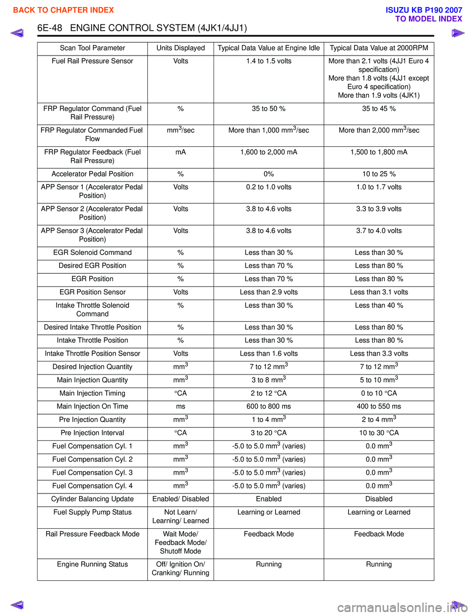
Fuel Rail Pressure SensorVolts1.4 to 1.5 volts More than 2.1 volts (4JJ1 Euro 4
specification)
More than 1.8 volts (4JJ1 except Euro 4 specification)
More than 1.9 volts (4JK1)
FRP Regulator Command (Fuel Rail Pressure) %
35 to 50 % 35 to 45 %
FRP Regulator Commanded Fuel Flow mm
3/sec More than 1,000 mm3/sec More than 2,000 mm3/sec
FRP Regulator Feedback (Fuel Rail Pressure) mA
1,600 to 2,000 mA 1,500 to 1,800 mA
Accelerator Pedal Position %0% 10 to 25 %
APP Sensor 1 (Accelerator Pedal Position) Volts
0.2 to 1.0 volts 1.0 to 1.7 volts
APP Sensor 2 (Accelerator Pedal Position) Volts
3.8 to 4.6 volts 3.3 to 3.9 volts
APP Sensor 3 (Accelerator Pedal Position) Volts
3.8 to 4.6 volts 3.7 to 4.0 volts
EGR Solenoid Command %Less than 30 % Less than 30 %
Desired EGR Position %Less than 70 % Less than 80 %
EGR Position %Less than 70 % Less than 80 %
EGR Position Sensor VoltsLess than 2.9 volts Less than 3.1 volts
Intake Throttle Solenoid Command %
Less than 30 % Less than 40 %
Desired Intake Throttle Position %Less than 30 % Less than 80 %
Intake Throttle Position %Less than 30 % Less than 80 %
Intake Throttle Position Sensor Volts Less than 1.6 voltsLess than 3.3 volts
Desired Injection Quantity mm
37 to 12 mm37 to 12 mm3
Main Injection Quantitymm33 to 8 mm35 to 10 mm3
Main Injection Timing°CA 2 to 12 °CA 0 to 10 °CA
Main Injection On Time ms600 to 800 ms 400 to 550 ms
Pre Injection Quantity mm
31 to 4 mm32 to 4 mm3
Pre Injection Interval°CA 3 to 20 °CA 10 to 30 °CA
Fuel Compensation Cyl. 1 mm
3-5.0 to 5.0 mm3 (varies)0.0 mm3
Fuel Compensation Cyl. 2 mm3-5.0 to 5.0 mm3 (varies)0.0 mm3
Fuel Compensation Cyl. 3 mm3-5.0 to 5.0 mm3 (varies)0.0 mm3
Fuel Compensation Cyl. 4 mm3-5.0 to 5.0 mm3 (varies)0.0 mm3
Cylinder Balancing Update Enabled/ Disabled EnabledDisabled
Fuel Supply Pump Status Not Learn/ Learning/ LearnedLearning or Learned
Learning or Learned
Rail Pressure Feedback Mode Wait Mode/ Feedback Mode/ Shutoff Mode Feedback Mode
Feedback Mode
Engine Running Status Off/ Ignition On/ Cranking/ Running Running
Running
Scan Tool Parameter Units Displayed Typical Data Value at Engine Idle Typical Data Value at 2000RPM
BACK TO CHAPTER INDEX
TO MODEL INDEX
ISUZU KB P190 2007
Page 1666 of 6020
ENGINE CONTROL SYSTEM (4JK1/4JJ1) 6E-49
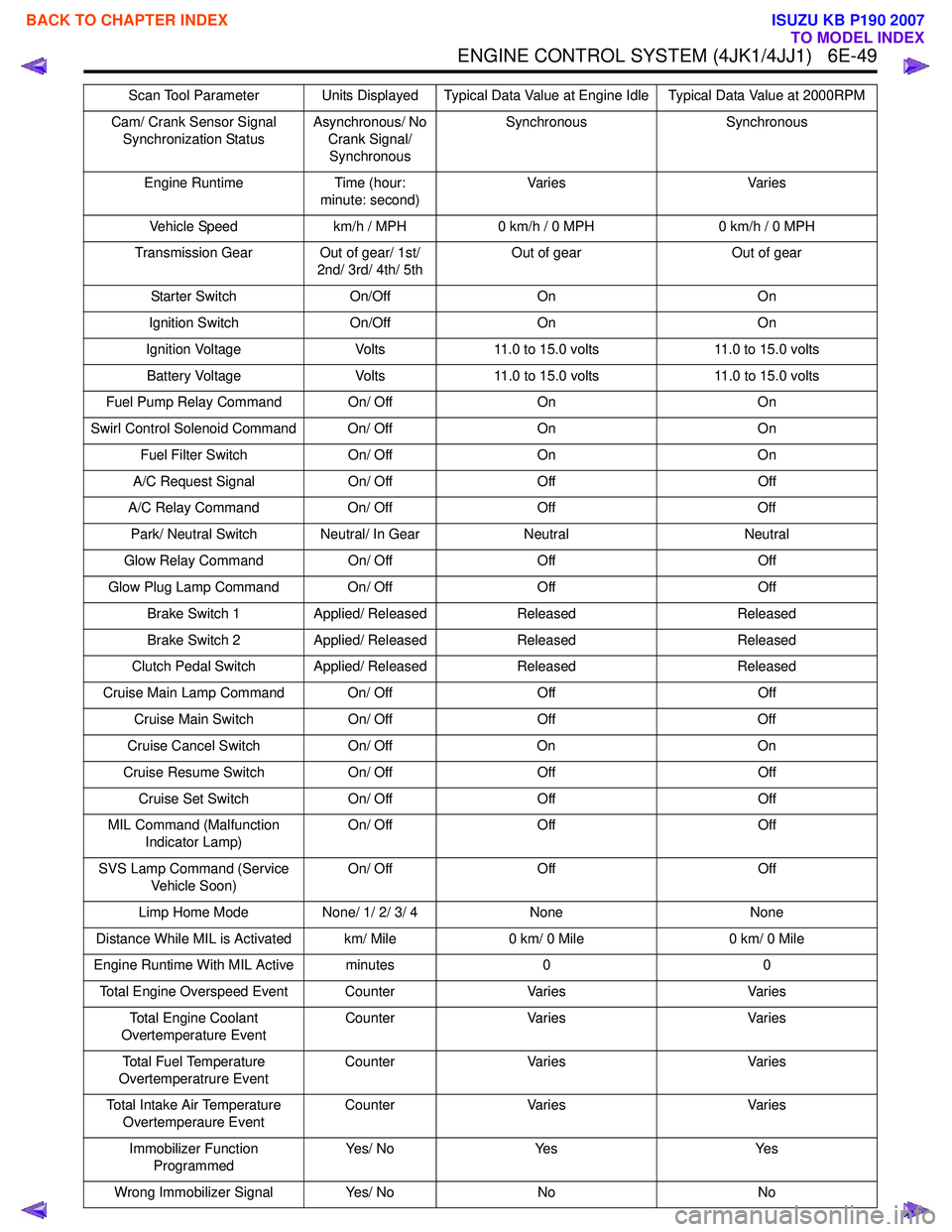
Cam/ Crank Sensor Signal Synchronization Status Asynchronous/ No
Crank Signal/ Synchronous Synchronous Synchronous
Engine Runtime Time (hour: minute: second) Va r i e s
Va r i e s
Vehicle Speed km/h / MPH0 km/h / 0 MPH 0 km/h / 0 MPH
Transmission Gear Out of gear/ 1st/ 2nd/ 3rd/ 4th/ 5th Out of gear
Out of gear
Starter Switch On/OffOn On
Ignition Switch On/OffOn On
Ignition Voltage Volts11.0 to 15.0 volts 11.0 to 15.0 volts
Battery Voltage Volts11.0 to 15.0 volts 11.0 to 15.0 volts
Fuel Pump Relay Command On/ Off OnOn
Swirl Control Solenoid Command On/ Off OnOn
Fuel Filter Switch On/ OffOn On
A/C Request Signal On/ OffOff Off
A/C Relay Command On/ OffOff Off
Park/ Neutral Switch Neutral/ In Gear NeutralNeutral
Glow Relay Command On/ OffOff Off
Glow Plug Lamp Command On/ Off OffOff
Brake Switch 1 Applied/ Released Released Released
Brake Switch 2 Applied/ Released Released Released
Clutch Pedal Switch Applied/ Released ReleasedReleased
Cruise Main Lamp Command On/ Off OffOff
Cruise Main Switch On/ OffOff Off
Cruise Cancel Switch On/ OffOn On
Cruise Resume Switch On/ OffOff Off
Cruise Set Switch On/ OffOff Off
MIL Command (Malfunction Indicator Lamp) On/ Off
Off Off
SVS Lamp Command (Service Vehicle Soon) On/ Off
Off Off
Limp Home Mode None/ 1/ 2/ 3/ 4 None None
Distance While MIL is Activated km/ Mile 0 km/ 0 Mile0 km/ 0 Mile
Engine Runtime With MIL Active minutes 00
Total Engine Overspeed Event Counter VariesVaries
Total Engine Coolant
Overtemperature Event Counter
Varies Varies
Total Fuel Temperature
Overtemperatrure Event Counter
Varies Varies
Total Intake Air Temperature Overtemperaure Event Counter
Varies Varies
Immobilizer Function Programmed Ye s / N o
Ye s Ye s
Wrong Immobilizer Signal Yes/ NoNo No
Scan Tool Parameter Units Displayed Typical Data Value at Engine Idle Typical Data Value at 2000RPM
BACK TO CHAPTER INDEX
TO MODEL INDEX
ISUZU KB P190 2007
Page 1667 of 6020
6E-50 ENGINE CONTROL SYSTEM (4JK1/4JJ1)
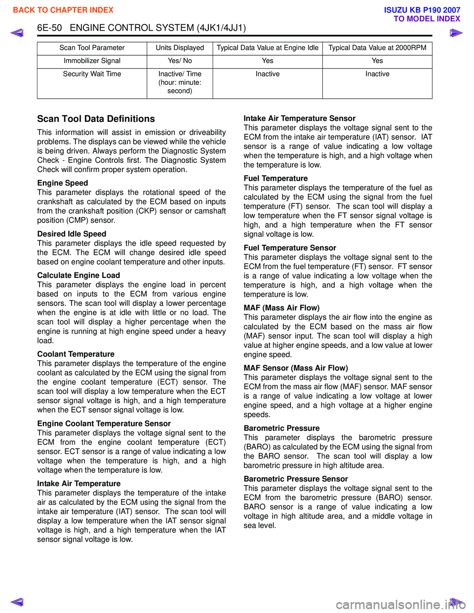
Scan Tool Data Definitions
This information will assist in emission or driveability
problems. The displays can be viewed while the vehicle
is being driven. Always perform the Diagnostic System
Check - Engine Controls first. The Diagnostic System
Check will confirm proper system operation.
Engine Speed
This parameter displays the rotational speed of the
crankshaft as calculated by the ECM based on inputs
from the crankshaft position (CKP) sensor or camshaft
position (CMP) sensor.
Desired Idle Speed
This parameter displays the idle speed requested by
the ECM. The ECM will change desired idle speed
based on engine coolant temperature and other inputs.
Calculate Engine Load
This parameter displays the engine load in percent
based on inputs to the ECM from various engine
sensors. The scan tool will display a lower percentage
when the engine is at idle with little or no load. The
scan tool will display a higher percentage when the
engine is running at high engine speed under a heavy
load.
Coolant Temperature
This parameter displays the temperature of the engine
coolant as calculated by the ECM using the signal from
the engine coolant temperature (ECT) sensor. The
scan tool will display a low temperature when the ECT
sensor signal voltage is high, and a high temperature
when the ECT sensor signal voltage is low.
Engine Coolant Temperature Sensor
This parameter displays the voltage signal sent to the
ECM from the engine coolant temperature (ECT)
sensor. ECT sensor is a range of value indicating a low
voltage when the temperature is high, and a high
voltage when the temperature is low.
Intake Air Temperature
This parameter displays the temperature of the intake
air as calculated by the ECM using the signal from the
intake air temperature (IAT) sensor. The scan tool will
display a low temperature when the IAT sensor signal
voltage is high, and a high temperature when the IAT
sensor signal voltage is low. Intake Air Temperature Sensor
This parameter displays the voltage signal sent to the
ECM from the intake air temperature (IAT) sensor. IAT
sensor is a range of value indicating a low voltage
when the temperature is high, and a high voltage when
the temperature is low.
Fuel Temperature
This parameter displays the temperature of the fuel as
calculated by the ECM using the signal from the fuel
temperature (FT) sensor. The scan tool will display a
low temperature when the FT sensor signal voltage is
high, and a high temperature when the FT sensor
signal voltage is low.
Fuel Temperature Sensor
This parameter displays the voltage signal sent to the
ECM from the fuel temperature (FT) sensor. FT sensor
is a range of value indicating a low voltage when the
temperature is high, and a high voltage when the
temperature is low.
MAF (Mass Air Flow)
This parameter displays the air flow into the engine as
calculated by the ECM based on the mass air flow
(MAF) sensor input. The scan tool will display a high
value at higher engine speeds, and a low value at lower
engine speed.
MAF Sensor (Mass Air Flow)
This parameter displays the voltage signal sent to the
ECM from the mass air flow (MAF) sensor. MAF sensor
is a range of value indicating a low voltage at lower
engine speed, and a high voltage at a higher engine
speeds.
Barometric Pressure
This parameter displays the barometric pressure
(BARO) as calculated by the ECM using the signal from
the BARO sensor. The scan tool will display a low
barometric pressure in high altitude area.
Barometric Pressure Sensor
This parameter displays the voltage signal sent to the
ECM from the barometric pressure (BARO) sensor.
BARO sensor is a range of value indicating a low
voltage in high altitude area, and a middle voltage in
sea level.
Immobilizer Signal Yes/ NoYes Yes
Security Wait Time Inactive/ Time
(hour: minute: second) Inactive
Inactive
Scan Tool Parameter Units Displayed Typical Data Value at Engine Idle Typical Data Value at 2000RPM
BACK TO CHAPTER INDEX
TO MODEL INDEX
ISUZU KB P190 2007
Page 1668 of 6020
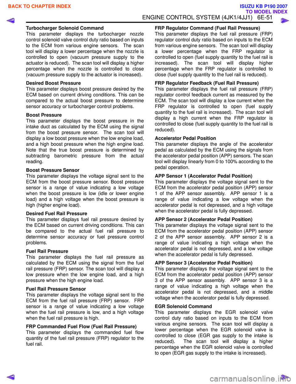
ENGINE CONTROL SYSTEM (4JK1/4JJ1) 6E-51
Turbocharger Solenoid Command
This parameter displays the turbocharger nozzle
control solenoid valve control duty ratio based on inputs
to the ECM from various engine sensors. The scan
tool will display a lower percentage when the nozzle is
controlled to open (vacuum pressure supply to the
actuator is reduced). The scan tool will display a higher
percentage when the nozzle is controlled to close
(vacuum pressure supply to the actuator is increased).
Desired Boost Pressure
This parameter displays boost pressure desired by the
ECM based on current driving conditions. This can be
compared to the actual boost pressure to determine
sensor accuracy or turbocharger control problems.
Boost Pressure
This parameter displays the boost pressure in the
intake duct as calculated by the ECM using the signal
from the boost pressure sensor. The scan tool will
display a low boost pressure when the low engine load,
and a high boost pressure when the high engine load.
Note that the true boost pressure is determined by
subtracting barometric pressure from the actual
reading.
Boost Pressure Sensor
This parameter displays the voltage signal sent to the
ECM from the boost pressure sensor. Boost pressure
sensor is a range of value indicating a low voltage
when the boost pressure is low (idle or lower engine
load) and a high voltage when the boost pressure is
high (higher engine load).
Desired Fuel Rail Pressure
This parameter displays fuel rail pressure desired by
the ECM based on current driving conditions. This can
be compared to the actual fuel rail pressure to
determine sensor accuracy or fuel pressure control
problems.
Fuel Rail Pressure
This parameter displays the fuel rail pressure as
calculated by the ECM using the signal from the fuel
rail pressure (FRP) sensor. The scan tool will display a
low pressure when the low engine load, and a high
pressure when the high engine load.
Fuel Rail Pressure Sensor
This parameter displays the voltage signal sent to the
ECM from the fuel rail pressure (FRP) sensor. FRP
sensor is a range of value indicating a low voltage
when the fuel rail pressure is low, and a high voltage
when the fuel rail pressure is high.
FRP Commanded Fuel Flow (Fuel Rail Pressure)
This parameter displays the commanded fuel flow
quantity of the fuel rail pressure (FRP) regulator to the
fuel rail. FRP Regulator Command (Fuel Rail Pressure)
This parameter displays the fuel rail pressure (FRP)
regulator control duty ratio based on inputs to the ECM
from various engine sensors. The scan tool will display
a lower percentage when the FRP regulator is
controlled to open (fuel supply quantity to the fuel rail is
increased). The scan tool will display higher
percentage when the FRP regulator is controlled to
close (fuel supply quantity to the fuel rail is reduced).
FRP Regulator Feedback (Fuel Rail Pressure)
This parameter displays the fuel rail pressure (FRP)
regulator control feedback current as measured by the
ECM. The scan tool will display a low current when the
FRP regulator is controlled to open (fuel supply
quantity to the fuel rail is increased). The scan tool will
display a high current when the FRP regulator is
controlled to close (fuel supply quantity to the fuel rail is
reduced).
Accelerator Pedal Position
This parameter displays the angle of the accelerator
pedal as calculated by the ECM using the signals from
the accelerator pedal position (APP) sensors. The scan
tool will display linearly from 0 to 100% according to the
pedal operation.
APP Sensor 1 (Accelerator Pedal Position)
This parameter displays the voltage signal sent to the
ECM from the accelerator pedal position (APP) sensor
1 of the APP sensor assembly. APP sensor 1 is a
range of value indicating a low voltage when the
accelerator pedal is not depressed, and a high voltage
when the accelerator pedal is fully depressed.
APP Sensor 2 (Accelerator Pedal Position)
This parameter displays the voltage signal sent to the
ECM from the accelerator pedal position (APP) sensor
2 of the APP sensor assembly. APP sensor 2 is a
range of value indicating a high voltage when the
accelerator pedal is not depressed, and a low voltage
when the accelerator pedal is fully depressed.
APP Sensor 3 (Accelerator Pedal Position)
This parameter displays the voltage signal sent to the
ECM from the accelerator pedal position (APP) sensor
3 of the APP sensor assembly. APP sensor 3 is a
range of value indicating a high voltage when the
accelerator pedal is not depressed, and a middle
voltage when the accelerator pedal is fully depressed.
EGR Solenoid Command
This parameter displays the EGR solenoid valve
control duty ratio based on inputs to the ECM from
various engine sensors. The scan tool will display a
lower percentage when the EGR solenoid valve is
controlled to close (EGR gas supply to the intake is
reduced). The scan tool will display a higher
percentage when the EGR solenoid valve is controlled
to open (EGR gas supply to the intake is increased).
BACK TO CHAPTER INDEX
TO MODEL INDEX
ISUZU KB P190 2007
Page 1669 of 6020
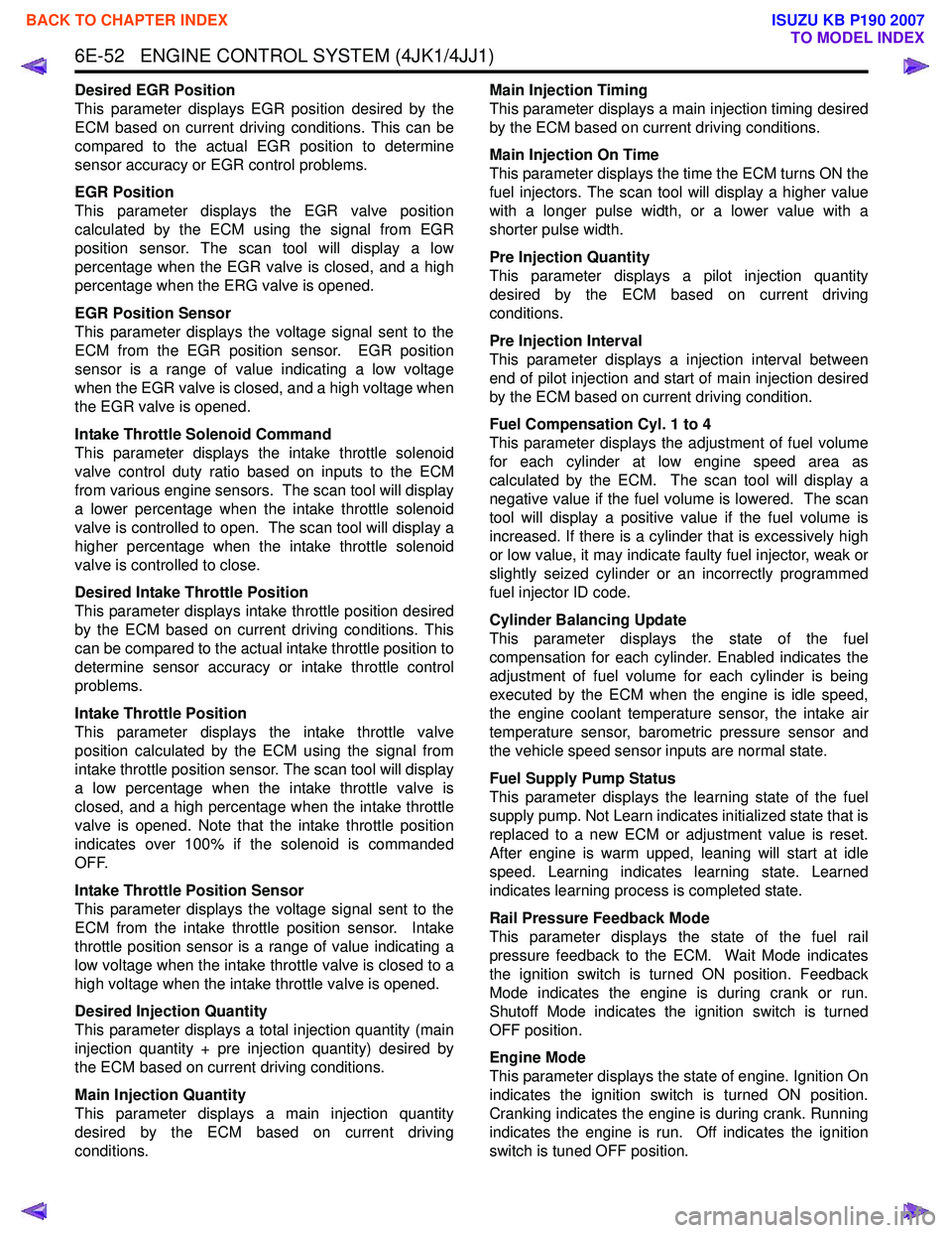
6E-52 ENGINE CONTROL SYSTEM (4JK1/4JJ1)
Desired EGR Position
This parameter displays EGR position desired by the
ECM based on current driving conditions. This can be
compared to the actual EGR position to determine
sensor accuracy or EGR control problems.
EGR Position
This parameter displays the EGR valve position
calculated by the ECM using the signal from EGR
position sensor. The scan tool will display a low
percentage when the EGR valve is closed, and a high
percentage when the ERG valve is opened.
EGR Position Sensor
This parameter displays the voltage signal sent to the
ECM from the EGR position sensor. EGR position
sensor is a range of value indicating a low voltage
when the EGR valve is closed, and a high voltage when
the EGR valve is opened.
Intake Throttle Solenoid Command
This parameter displays the intake throttle solenoid
valve control duty ratio based on inputs to the ECM
from various engine sensors. The scan tool will display
a lower percentage when the intake throttle solenoid
valve is controlled to open. The scan tool will display a
higher percentage when the intake throttle solenoid
valve is controlled to close.
Desired Intake Throttle Position
This parameter displays intake throttle position desired
by the ECM based on current driving conditions. This
can be compared to the actual intake throttle position to
determine sensor accuracy or intake throttle control
problems.
Intake Throttle Position
This parameter displays the intake throttle valve
position calculated by the ECM using the signal from
intake throttle position sensor. The scan tool will display
a low percentage when the intake throttle valve is
closed, and a high percentage when the intake throttle
valve is opened. Note that the intake throttle position
indicates over 100% if the solenoid is commanded
OFF.
Intake Throttle Position Sensor
This parameter displays the voltage signal sent to the
ECM from the intake throttle position sensor. Intake
throttle position sensor is a range of value indicating a
low voltage when the intake throttle valve is closed to a
high voltage when the intake throttle valve is opened.
Desired Injection Quantity
This parameter displays a total injection quantity (main
injection quantity + pre injection quantity) desired by
the ECM based on current driving conditions.
Main Injection Quantity
This parameter displays a main injection quantity
desired by the ECM based on current driving
conditions. Main Injection Timing
This parameter displays a main injection timing desired
by the ECM based on current driving conditions.
Main Injection On Time
This parameter displays the time the ECM turns ON the
fuel injectors. The scan tool will display a higher value
with a longer pulse width, or a lower value with a
shorter pulse width.
Pre Injection Quantity
This parameter displays a pilot injection quantity
desired by the ECM based on current driving
conditions.
Pre Injection Interval
This parameter displays a injection interval between
end of pilot injection and start of main injection desired
by the ECM based on current driving condition.
Fuel Compensation Cyl. 1 to 4
This parameter displays the adjustment of fuel volume
for each cylinder at low engine speed area as
calculated by the ECM. The scan tool will display a
negative value if the fuel volume is lowered. The scan
tool will display a positive value if the fuel volume is
increased. If there is a cylinder that is excessively high
or low value, it may indicate faulty fuel injector, weak or
slightly seized cylinder or an incorrectly programmed
fuel injector ID code.
Cylinder Balancing Update
This parameter displays the state of the fuel
compensation for each cylinder. Enabled indicates the
adjustment of fuel volume for each cylinder is being
executed by the ECM when the engine is idle speed,
the engine coolant temperature sensor, the intake air
temperature sensor, barometric pressure sensor and
the vehicle speed sensor inputs are normal state.
Fuel Supply Pump Status
This parameter displays the learning state of the fuel
supply pump. Not Learn indicates initialized state that is
replaced to a new ECM or adjustment value is reset.
After engine is warm upped, leaning will start at idle
speed. Learning indicates learning state. Learned
indicates learning process is completed state.
Rail Pressure Feedback Mode
This parameter displays the state of the fuel rail
pressure feedback to the ECM. Wait Mode indicates
the ignition switch is turned ON position. Feedback
Mode indicates the engine is during crank or run.
Shutoff Mode indicates the ignition switch is turned
OFF position.
Engine Mode
This parameter displays the state of engine. Ignition On
indicates the ignition switch is turned ON position.
Cranking indicates the engine is during crank. Running
indicates the engine is run. Off indicates the ignition
switch is tuned OFF position.
BACK TO CHAPTER INDEX
TO MODEL INDEX
ISUZU KB P190 2007
Page 1670 of 6020
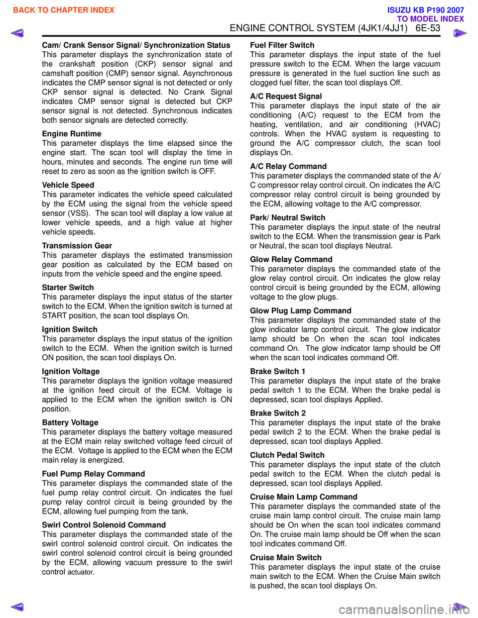
ENGINE CONTROL SYSTEM (4JK1/4JJ1) 6E-53
Cam/ Crank Sensor Signal/ Synchronization Status
This parameter displays the synchronization state of
the crankshaft position (CKP) sensor signal and
camshaft position (CMP) sensor signal. Asynchronous
indicates the CMP sensor signal is not detected or only
CKP sensor signal is detected. No Crank Signal
indicates CMP sensor signal is detected but CKP
sensor signal is not detected. Synchronous indicates
both sensor signals are detected correctly.
Engine Runtime
This parameter displays the time elapsed since the
engine start. The scan tool will display the time in
hours, minutes and seconds. The engine run time will
reset to zero as soon as the ignition switch is OFF.
Vehicle Speed
This parameter indicates the vehicle speed calculated
by the ECM using the signal from the vehicle speed
sensor (VSS). The scan tool will display a low value at
lower vehicle speeds, and a high value at higher
vehicle speeds.
Transmission Gear
This parameter displays the estimated transmission
gear position as calculated by the ECM based on
inputs from the vehicle speed and the engine speed.
Starter Switch
This parameter displays the input status of the starter
switch to the ECM. When the ignition switch is turned at
START position, the scan tool displays On.
Ignition Switch
This parameter displays the input status of the ignition
switch to the ECM. When the ignition switch is turned
ON position, the scan tool displays On.
Ignition Voltage
This parameter displays the ignition voltage measured
at the ignition feed circuit of the ECM. Voltage is
applied to the ECM when the ignition switch is ON
position.
Battery Voltage
This parameter displays the battery voltage measured
at the ECM main relay switched voltage feed circuit of
the ECM. Voltage is applied to the ECM when the ECM
main relay is energized.
Fuel Pump Relay Command
This parameter displays the commanded state of the
fuel pump relay control circuit. On indicates the fuel
pump relay control circuit is being grounded by the
ECM, allowing fuel pumping from the tank.
Swirl Control Solenoid Command
This parameter displays the commanded state of the
swirl control solenoid control circuit. On indicates the
swirl control solenoid control circuit is being grounded
by the ECM, allowing vacuum pressure to the swirl
control
actuator. Fuel Filter Switch
This parameter displays the input state of the fuel
pressure switch to the ECM. When the large vacuum
pressure is generated in the fuel suction line such as
clogged fuel filter, the scan tool displays Off.
A/C Request Signal
This parameter displays the input state of the air
conditioning (A/C) request to the ECM from the
heating, ventilation, and air conditioning (HVAC)
controls. When the HVAC system is requesting to
ground the A/C compressor clutch, the scan tool
displays On.
A/C Relay Command
This parameter displays the commanded state of the A/
C compressor relay control circuit. On indicates the A/C
compressor relay control circuit is being grounded by
the ECM, allowing voltage to the A/C compressor.
Park/ Neutral Switch
This parameter displays the input state of the neutral
switch to the ECM. When the transmission gear is Park
or Neutral, the scan tool displays Neutral.
Glow Relay Command
This parameter displays the commanded state of the
glow relay control circuit. On indicates the glow relay
control circuit is being grounded by the ECM, allowing
voltage to the glow plugs.
Glow Plug Lamp Command
This parameter displays the commanded state of the
glow indicator lamp control circuit. The glow indicator
lamp should be On when the scan tool indicates
command On. The glow indicator lamp should be Off
when the scan tool indicates command Off.
Brake Switch 1
This parameter displays the input state of the brake
pedal switch 1 to the ECM. When the brake pedal is
depressed, scan tool displays Applied.
Brake Switch 2
This parameter displays the input state of the brake
pedal switch 2 to the ECM. When the brake pedal is
depressed, scan tool displays Applied.
Clutch Pedal Switch
This parameter displays the input state of the clutch
pedal switch to the ECM. When the clutch pedal is
depressed, scan tool displays Applied.
Cruise Main Lamp Command
This parameter displays the commanded state of the
cruise main lamp control circuit. The cruise main lamp
should be On when the scan tool indicates command
On. The cruise main lamp should be Off when the scan
tool indicates command Off.
Cruise Main Switch
This parameter displays the input state of the cruise
main switch to the ECM. When the Cruise Main switch
is pushed, the scan tool displays On.
BACK TO CHAPTER INDEX
TO MODEL INDEX
ISUZU KB P190 2007
Page 1681 of 6020
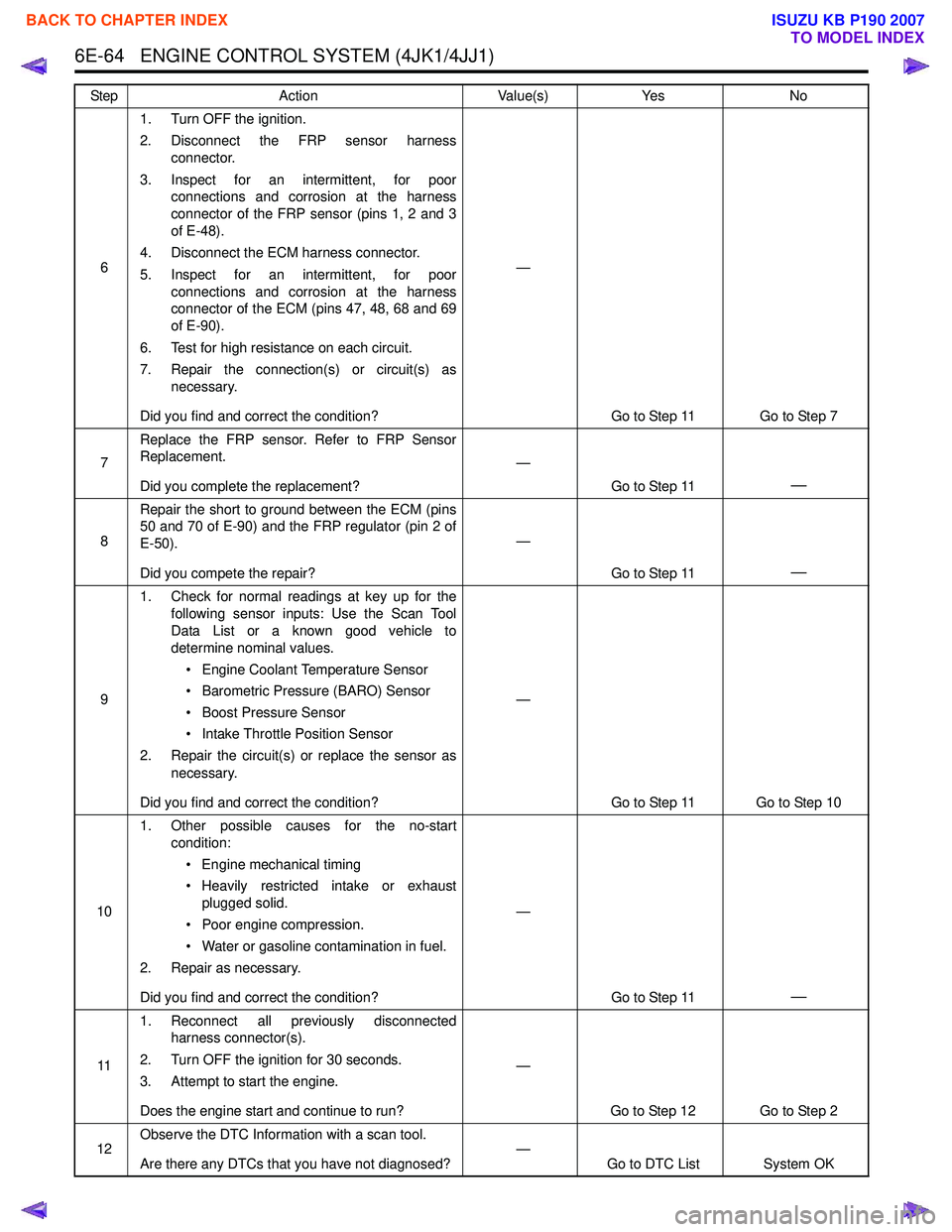
6E-64 ENGINE CONTROL SYSTEM (4JK1/4JJ1)
61. Turn OFF the ignition.
2. Disconnect the FRP sensor harness connector.
3. Inspect for an intermittent, for poor connections and corrosion at the harness
connector of the FRP sensor (pins 1, 2 and 3
of E-48).
4. Disconnect the ECM harness connector.
5. Inspect for an intermittent, for poor connections and corrosion at the harness
connector of the ECM (pins 47, 48, 68 and 69
of E-90).
6. Test for high resistance on each circuit.
7. Repair the connection(s) or circuit(s) as necessary.
Did you find and correct the condition? —
Go to Step 11 Go to Step 7
7 Replace the FRP sensor. Refer to FRP Sensor
Replacement.
Did you complete the replacement? —
Go to Step 11
—
8Repair the short to ground between the ECM (pins
50 and 70 of E-90) and the FRP regulator (pin 2 of
E-50).
Did you compete the repair? —
Go to Step 11
—
91. Check for normal readings at key up for the
following sensor inputs: Use the Scan Tool
Data List or a known good vehicle to
determine nominal values.
• Engine Coolant Temperature Sensor
• Barometric Pressure (BARO) Sensor
• Boost Pressure Sensor
• Intake Throttle Position Sensor
2. Repair the circuit(s) or replace the sensor as necessary.
Did you find and correct the condition? —
Go to Step 11 Go to Step 10
10 1. Other possible causes for the no-start
condition:
• Engine mechanical timing
• Heavily restricted intake or exhaust plugged solid.
• Poor engine compression.
• Water or gasoline contamination in fuel.
2. Repair as necessary.
Did you find and correct the condition? —
Go to Step 11
—
111. Reconnect all previously disconnected
harness connector(s).
2. Turn OFF the ignition for 30 seconds.
3. Attempt to start the engine.
Does the engine start and continue to run? —
Go to Step 12 Go to Step 2
12 Observe the DTC Information with a scan tool.
Are there any DTCs that you have not diagnosed? —
Go to DTC List System OK
Step
Action Value(s)Yes No
BACK TO CHAPTER INDEX
TO MODEL INDEX
ISUZU KB P190 2007