2007 ISUZU KB P190 engine
[x] Cancel search: enginePage 3907 of 6020
Automatic Transmission – 4L60E – Electrical Diagnosis Page 7C2–121
Step Action Yes No
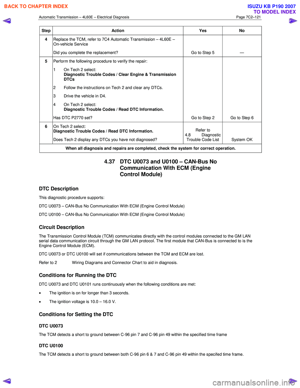
4 Replace the TCM, refer to 7C4 Automatic Transmission – 4L60E –
On-vehicle Service
Did you complete the replacement? Go to Step 5 —
5 Perform the following procedure to verify the repair:
1 On Tech 2 select: Diagnostic Trouble Codes / Clear Engine & Transmission
DTCs
2 Follow the instructions on Tech 2 and clear any DTCs.
3 Drive the vehicle in D4.
4 On Tech 2 select:
Diagnostic Trouble Codes / Read DTC Information.
Has DTC P2770 set? Go to Step 2 Go to Step 6
6 On Tech 2 select:
Diagnostic Trouble Codes / Read DTC Information.
Does Tech 2 display any DTCs you have not diagnosed? Refer to
4.8 Diagnostic Trouble Code List System OK
When all diagnosis and repairs are completed, check the
system for correct operation.
4.37 DTC U0073 and U0100 – CAN-Bus No
Communication With ECM (Engine
Control Module)
DTC Description
This diagnostic procedure supports:
DTC U0073 – CAN-Bus No Communication W ith ECM (Engine Control Module)
DTC U0100 – CAN-Bus No Communication W ith ECM (Engine Control Module)
Circuit Description
The Transmission Control Module (TCM) communicates directly with the control modules connected to the GM LAN
serial data communication circuit through the GM LAN protocol. The first module that CAN-Bus is connected to is the
Engine Control Module (ECM).
DTC U0073 or DTC U0100 will set if communications between the TCM and ECM are lost.
Refer to 2 W iring Diagrams and Connector Chart to aid in diagnosis.
Conditions for Running the DTC
DTC U0073 and DTC U0101 runs continuously when the following conditions are met:
• The ignition is on for longer than 3 seconds.
• The ignition voltage is 10.0 – 16.0 V.
Conditions for Setting the DTC
DTC U0073
The TCM detects a short to ground between C-96 pin 7 and C-96 pin 49 within the specified time frame
DTC U0100
The TCM detects a short to ground between both C-96 pin 6 & 7 and C-96 pin 49 within the specifed time frame.
BACK TO CHAPTER INDEX
TO MODEL INDEX
ISUZU KB P190 2007
Page 3909 of 6020
Automatic Transmission – 4L60E – Electrical Diagnosis Page 7C2–123
Step Action Yes No
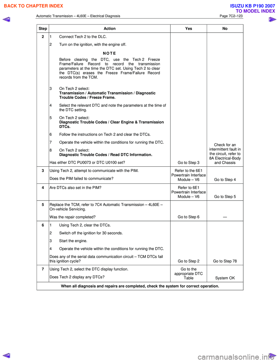
2 1 Connect Tech 2 to the DLC.
2 Turn on the ignition, with the engine off.
NOTE
Before clearing the DTC, use the Tech 2 Freeze
Frame/Failure Record to record the transmission
parameters at the time the DTC set. Using Tech 2 to clear
the DTC(s) erases the Freeze Frame/Failure Record
records from the TCM.
3 On Tech 2 select: Transmission / Automatic Transmission / Diagnostic
Trouble Codes / Freeze Frame.
4 Select the relevant DTC and note the parameters at the time of the DTC setting.
5 On Tech 2 select:
Diagnostic Trouble Codes / Clear Engine & Transmission
DTCs.
6 Follow the instructions on Tech 2 and clear the DTCs.
7 Operate the vehicle within the conditions for running the DTC.
8 On Tech 2 select:
Diagnostic Trouble Codes / Read DTC Information.
Has either DTC PU0073 or DTC U0100 set? Go to Step 3 Check for an
intermittent fault in the circuit, refer to
8A Electrical-Body and Chassis
3 Using Tech 2, attempt to communicate with the PIM.
Does the PIM failed to communicate? Refer to the 6E1
Powertrain Interface Module – V6 Go to Step 4
4 Are DTCs also set in the PIM? Refer to 6E1
Powertrain Interface
Module – V6 Go to Step 5
5 Replace the TCM, refer to 7C4 Automatic Transmission – 4L60E –
On-vehicle Servicing.
Was the repair completed? Go to Step 6
—
6 1 Using Tech 2, clear the DTCs.
2 Switch off the ignition for 30 seconds.
3 Start the engine.
4 Operate the vehicle within the conditions for running the DTC.
Does any of the serial data communication circuit – TCM DTCs fail
this ignition cycle? Go to Step 2 Go to Step 78
7 Using Tech 2, select the DTC display function.
Does Tech 2 display any DTCs? Go to the
appropriate DTC Table System OK
When all diagnosis and repairs are completed, check the system for correct operation.
BACK TO CHAPTER INDEX
TO MODEL INDEX
ISUZU KB P190 2007
Page 3918 of 6020
Automatic Transmission – 4L60E – On-vehicle Servicing Page 7C4–5
2 Maintenance Operations
2.1 Transmission Fluid
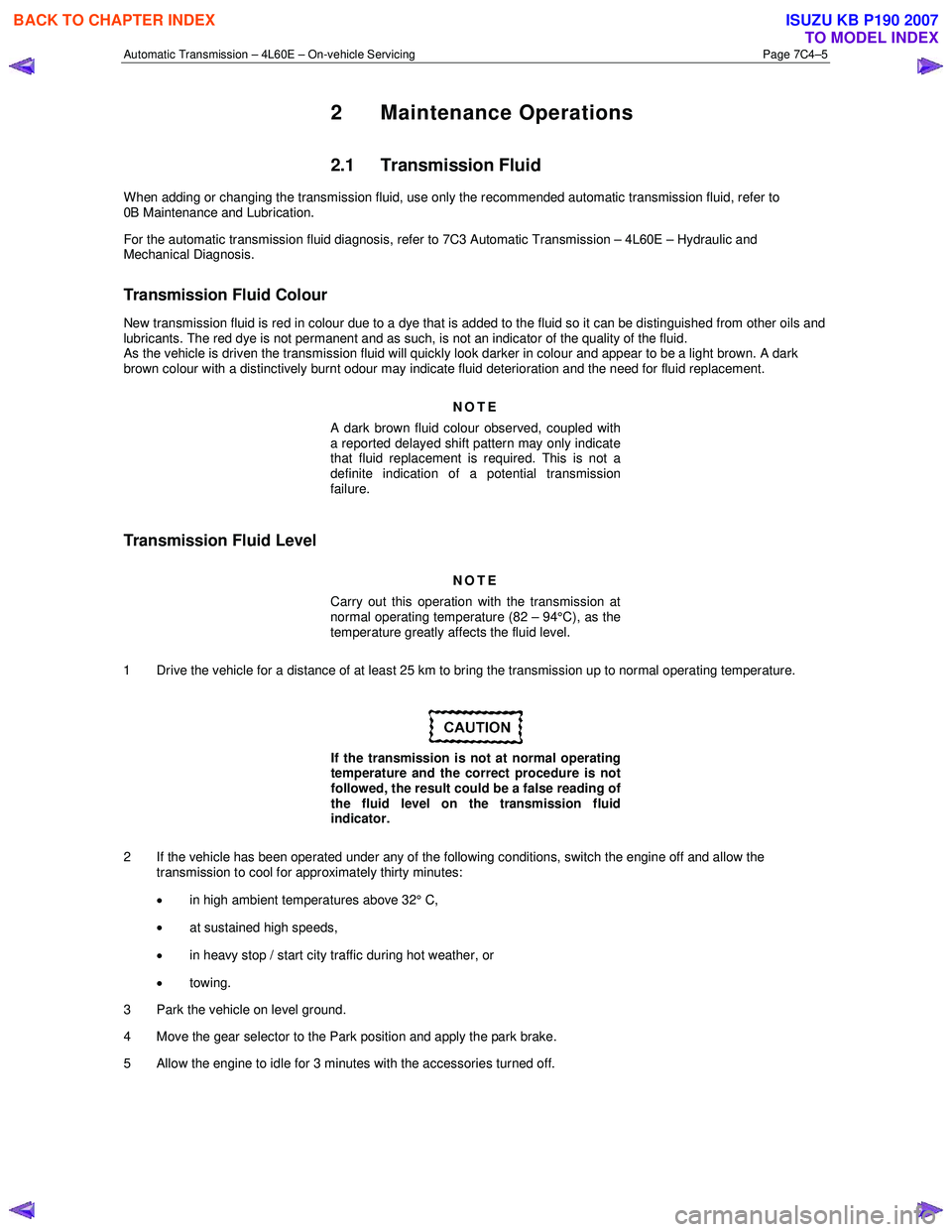
When adding or changing the transmission fluid, use only the recommended automatic transmission fluid, refer to
0B Maintenance and Lubrication.
For the automatic transmission fluid diagnosis, refer to 7C3 Automatic Transmission – 4L60E – Hydraulic and
Mechanical Diagnosis.
Transmission Fluid Colour
New transmission fluid is red in colour due to a dye that is added to the fluid so it can be distinguished from other oils and
lubricants. The red dye is not permanent and as such, is not an indicator of the quality of the fluid.
As the vehicle is driven the transmission fluid will quickly look darker in colour and appear to be a light brown. A dark
brown colour with a distinctively burnt odour may indicate fluid deterioration and the need for fluid replacement.
NOTE
A dark brown fluid colour observed, coupled with
a reported delayed shift pattern may only indicate
that fluid replacement is required. This is not a
definite indication of a potential transmission
failure.
Transmission Fluid Level
NOTE
Carry out this operation with the transmission at
normal operating temperature (82 – 94°C), as the
temperature greatly affects the fluid level.
1 Drive the vehicle for a distance of at least 25 km to bring the transmission up to normal operating temperature.
If the transmission is not at normal operating
temperature and the correct procedure is not
followed, the result could be a false reading of
the fluid level on the transmission fluid
indicator.
2 If the vehicle has been operated under any of the following conditions, switch the engine off and allow the transmission to cool for approximately thirty minutes:
• in high ambient temperatures above 32° C,
• at sustained high speeds,
• in heavy stop / start city traffic during hot weather, or
• towing.
3 Park the vehicle on level ground.
4 Move the gear selector to the Park position and apply the park brake.
5 Allow the engine to idle for 3 minutes with the accessories turned off.
BACK TO CHAPTER INDEX
TO MODEL INDEX
ISUZU KB P190 2007
Page 3920 of 6020
Automatic Transmission – 4L60E – On-vehicle Servicing Page 7C4–7
NOTE
This will also flush the cooler hose/line
assemblies and cooler with transmission fluid.
7 If the flow rate is satisfactory, reconnect the cooler inlet line to the transmission, refer to 3.17 Transmission Cooler Line/Hose Assemblies.
8 Lower the vehicle, check and top up the transmission fluid to the correct level as required, refer to 2.1 Transmission Fluid.
Flow Rate Test
Do not run the engine any longer than
absolutely necessary, as a fluid level too low
can cause aeration and foaming.
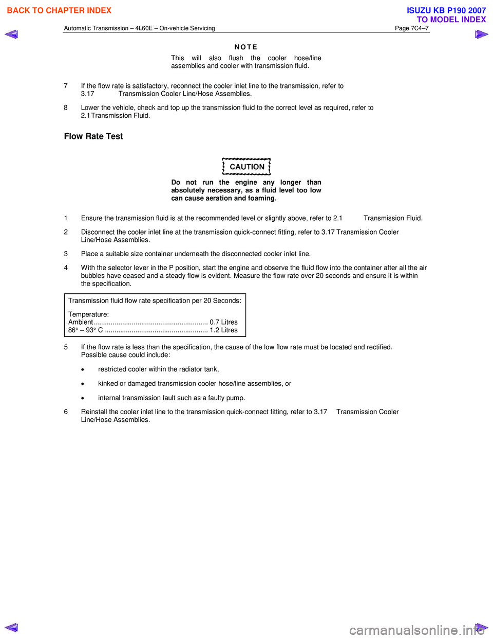
1 Ensure the transmission fluid is at the recommended level or slightly above, refer to 2.1 Transmission Fluid.
2 Disconnect the cooler inlet line at the transmission quick-connect fitting, refer to 3.17 Transmission Cooler Line/Hose Assemblies.
3 Place a suitable size container underneath the disconnected cooler inlet line.
4 W ith the selector lever in the P position, start the engine and observe the fluid flow into the container after all the air bubbles have ceased and a steady flow is evident. Measure the flow rate over 20 seconds and ensure it is within
the specification.
Transmission fluid flow rate specification per 20 Seconds:
Temperature: Ambient ............................................................ 0.7 Litres 86° – 93° C ...................................................... 1.2 Litres
5 If the flow rate is less than the specification, the cause of the low flow rate must be located and rectified. Possible cause could include:
• restricted cooler within the radiator tank,
• kinked or damaged transmission cooler hose/line assemblies, or
• internal transmission fault such as a faulty pump.
6 Reinstall the cooler inlet line to the transmission quick-connect fitting, refer to 3.17 Transmission Cooler Line/Hose Assemblies.
BACK TO CHAPTER INDEX
TO MODEL INDEX
ISUZU KB P190 2007
Page 3929 of 6020
Automatic Transmission – 4L60E – On-vehicle Servicing Page 7C4–16
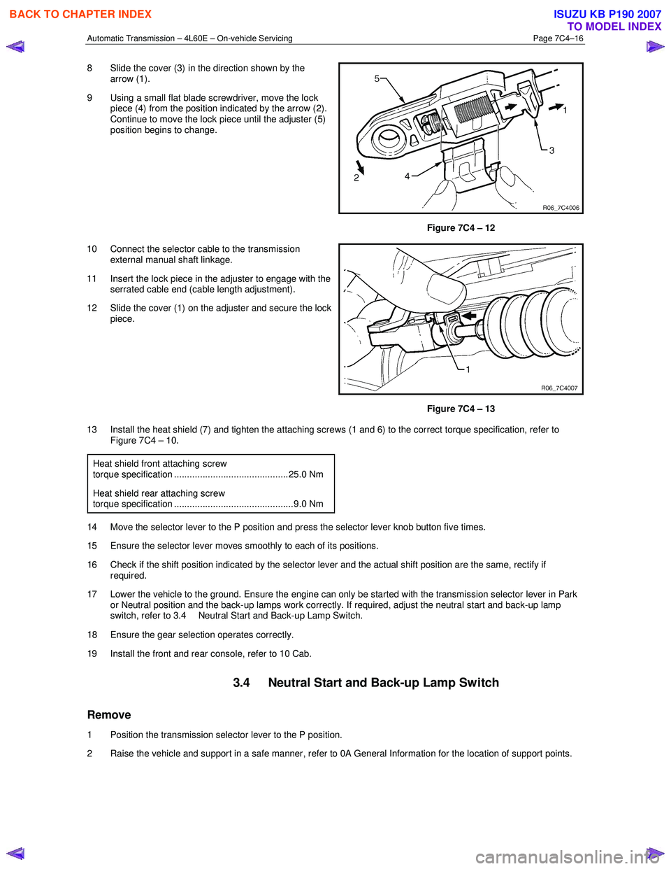
8 Slide the cover (3) in the direction shown by the
arrow (1).
9 Using a small flat blade screwdriver, move the lock piece (4) from the position indicated by the arrow (2).
Continue to move the lock piece until the adjuster (5)
position begins to change.
Figure 7C4 – 12
10 Connect the selector cable to the transmission external manual shaft linkage.
11 Insert the lock piece in the adjuster to engage with the serrated cable end (cable length adjustment).
12 Slide the cover (1) on the adjuster and secure the lock piece.
Figure 7C4 – 13
13 Install the heat shield (7) and tighten the attaching screws (1 and 6) to the correct torque specification, refer to Figure 7C4 – 10.
Heat shield front attaching screw
torque specification ............................................ 25.0 Nm
Heat shield rear attaching screw torque specification ..............................................9.0 Nm
14 Move the selector lever to the P position and press the selector lever knob button five times.
15 Ensure the selector lever moves smoothly to each of its positions.
16 Check if the shift position indicated by the selector lever and the actual shift position are the same, rectify if required.
17 Lower the vehicle to the ground. Ensure the engine can only be started with the transmission selector lever in Park or Neutral position and the back-up lamps work correctly. If required, adjust the neutral start and back-up lamp
switch, refer to 3.4 Neutral Start and Back-up Lamp Switch.
18 Ensure the gear selection operates correctly.
19 Install the front and rear console, refer to 10 Cab.
3.4 Neutral Start and Back-up Lamp Switch
Remove
1 Position the transmission selector lever to the P position.
2 Raise the vehicle and support in a safe manner, refer to 0A General Information for the location of support points.
BACK TO CHAPTER INDEX
TO MODEL INDEX
ISUZU KB P190 2007
Page 3931 of 6020
Automatic Transmission – 4L60E – On-vehicle Servicing Page 7C4–18
Ensure the four wheels are off the ground
before performing the starting test.
4 W ith the ignition switched to the ON position, check if the engine can only be started in the Park and Neutral shift selector positions and ensure the back-up lamps illuminate when Reverse is selected. A further minor adjustment
may be required to achieve this state.
NOTE
To gain access to the rear attaching screw (11) it
will be necessary to remove the connector.
5 After the switch has been adjusted, tighten the rear attaching screw (11) to the correct torque specification. Neutral start and back-up lamp switch
attaching screw torque specification .................. 25.0 Nm
6 Reinstall the connector and the CPA securing pin.
7 Remove the switch front attaching screw (1).
8 Install the heat shield (3) and tighten the attaching screws (1 and 2) to the correct torque specification.
Heat shield front attaching screw
torque specification ............................................ 25.0 Nm
Heat shield rear attaching screw torque specification ..............................................9.0 Nm
9 Lower the vehicle to the ground and re-check the operation of the neutral start and back-up lamp switch. The vehicle must start only with the shift selector in the Park or Neutral positions and the back-up lamps should only
illuminate when Reverse is selected.
3.5 Vehicle Speed Sensor
NOTE
For the speed sensor fitted to four wheel drive
vehicles (4WD), refer to 7D Transfer Case and
Adaptor Housing.
Remove
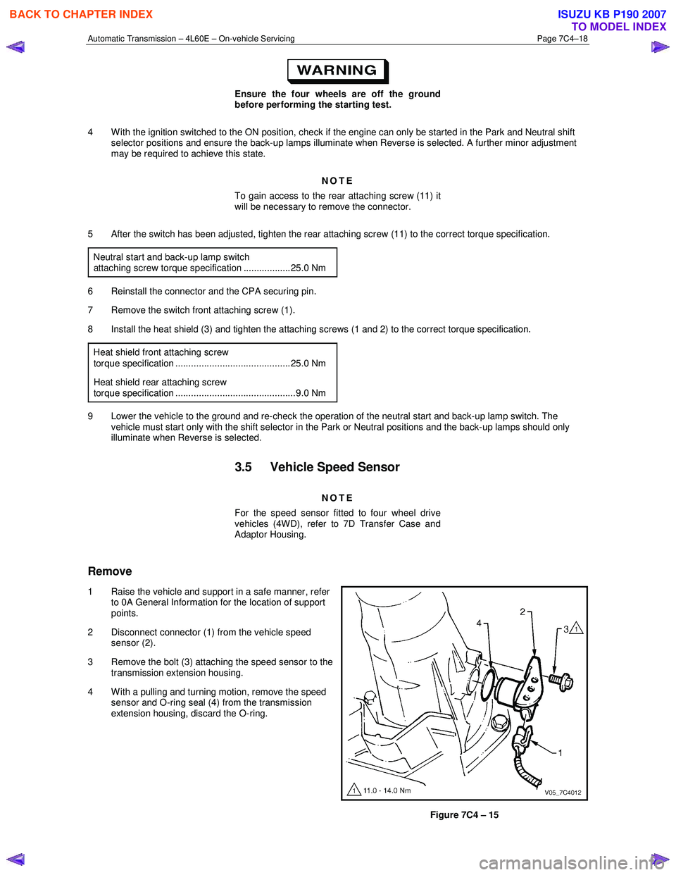
1 Raise the vehicle and support in a safe manner, refer
to 0A General Information for the location of support
points.
2 Disconnect connector (1) from the vehicle speed sensor (2).
3 Remove the bolt (3) attaching the speed sensor to the transmission extension housing.
4 With a pulling and turning motion, remove the speed sensor and O-ring seal (4) from the transmission
extension housing, discard the O-ring.
Figure 7C4 – 15
BACK TO CHAPTER INDEX
TO MODEL INDEX
ISUZU KB P190 2007
Page 3953 of 6020

Automatic Transmission – 4L60E – On-vehicle Servicing Page 7C4–40
5 Remove the filler tube from the engine compartment.
6 Remove the filler tube seal from the transmission case and discard.
7 If the breather hose needs to be replaced proceed as follows: a unclip the breather hose (4) from the harness channel (5).
b Remove the transmission support and lower the rear of the transmission sufficiently to get access to the breather hose, refer to 3.7 Transmission Support and Mount.
c Disconnect the breather hose from the T-joint (6) and the top of the transmission case and remove.
d If required, remove the two bolts (7) attaching the brackets of the vent pipe (8) to the chassis, disconnect from the T-joint and remove the vent pipe.
Figure 7C4 – 57
Reinstall
Reinstallation of the transmission filler tube and/or the breather hose is the reverse of the removal procedure, noting the
following:
1 Smear a new filler tube seal with clean transmission fluid and fit it to the transmission case.
2 Ensure the transmission breather hose and the harness are secured to the filler tube lower bracket.
3 Tighten the bolt attaching the filler tube bracket to the correct torque specification.
Filler tube bracket attaching bolt
torque specification ................................. 20.0 – 35.0 Nm
4 If required, tighten the two bolts attaching the vent pipe bracket to the chassis to the correct torque specification.
Vent pipe attaching bolt
torque specification ..............................................6.0 Nm
BACK TO CHAPTER INDEX
TO MODEL INDEX
ISUZU KB P190 2007
Page 3954 of 6020
Automatic Transmission – 4L60E – On-vehicle Servicing Page 7C4–41
3.17 Transmission Cooler Line/Hose
Assemblies
Remove
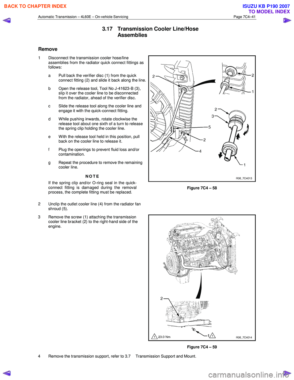
1 Disconnect the transmission cooler hose/line assemblies from the radiator quick connect fittings as
follows:
a Pull back the verifier disc (1) from the quick connect fitting (2) and slide it back along the line.
b Open the release tool, Tool No J-41623-B (3), slip it over the cooler line to be disconnected
from the radiator, ahead of the verifier disc.
c Slide the release tool along the cooler line and engage it with the quick-connect fitting.
d W hile pushing inwards, rotate clockwise the release tool about one sixth of a turn to release
the spring clip holding the cooler line.
e With the release tool held in this position, pull back on the cooler line to release it.
f Plug the openings to prevent fluid loss and/or contamination.
g Repeat the procedure to remove the remaining cooler line.
NOTE
If the spring clip and/or O-ring seal in the quick-
connect fitting is damaged during the removal
process, the complete fitting must be replaced.
2 Unclip the outlet cooler line (4) from the radiator fan shroud (5).
Figure 7C4 – 58
3 Remove the screw (1) attaching the transmission cooler line bracket (2) to the right-hand side of the
engine.
Figure 7C4 – 59
4 Remove the transmission support, refer to 3.7 Transmission Support and Mount.
BACK TO CHAPTER INDEX
TO MODEL INDEX
ISUZU KB P190 2007