2007 ISUZU KB P190 engine
[x] Cancel search: enginePage 3955 of 6020
Automatic Transmission – 4L60E – On-vehicle Servicing Page 7C4–42
5 Carefully lower the rear of the transmission sufficiently to get access to the cooler lines.
6 Place a suitable sized drip tray underneath the transmission.
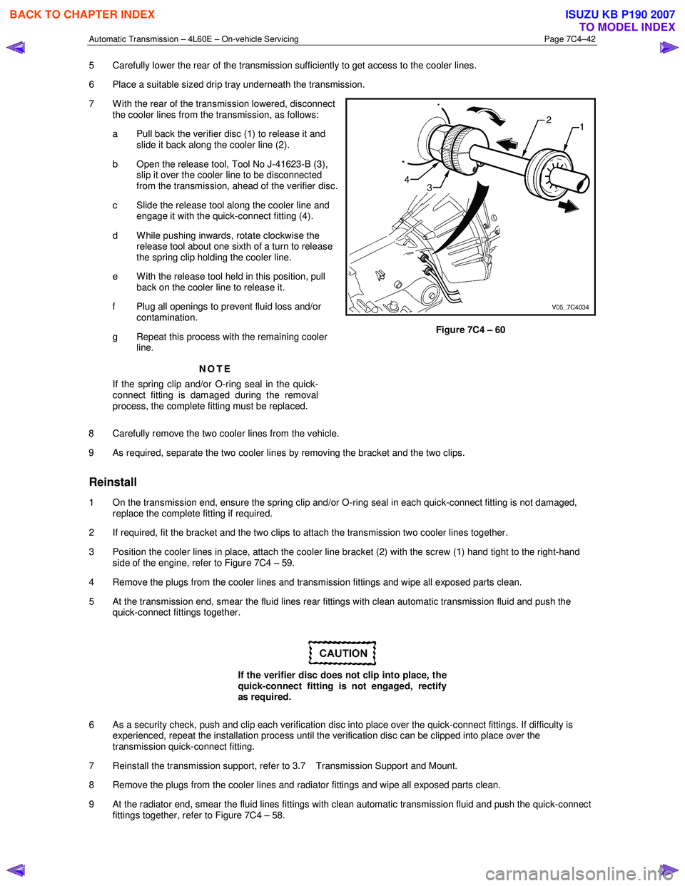
7 W ith the rear of the transmission lowered, disconnect the cooler lines from the transmission, as follows:
a Pull back the verifier disc (1) to release it and slide it back along the cooler line (2).
b Open the release tool, Tool No J-41623-B (3), slip it over the cooler line to be disconnected
from the transmission, ahead of the verifier disc.
c Slide the release tool along the cooler line and engage it with the quick-connect fitting (4).
d W hile pushing inwards, rotate clockwise the release tool about one sixth of a turn to release
the spring clip holding the cooler line.
e With the release tool held in this position, pull back on the cooler line to release it.
f Plug all openings to prevent fluid loss and/or contamination.
g Repeat this process with the remaining cooler line.
NOTE
If the spring clip and/or O-ring seal in the quick-
connect fitting is damaged during the removal
process, the complete fitting must be replaced.
Figure 7C4 – 60
8 Carefully remove the two cooler lines from the vehicle.
9 As required, separate the two cooler lines by removing the bracket and the two clips.
Reinstall
1 On the transmission end, ensure the spring clip and/or O-ring seal in each quick-connect fitting is not damaged, replace the complete fitting if required.
2 If required, fit the bracket and the two clips to attach the transmission two cooler lines together.
3 Position the cooler lines in place, attach the cooler line bracket (2) with the screw (1) hand tight to the right-hand side of the engine, refer to Figure 7C4 – 59.
4 Remove the plugs from the cooler lines and transmission fittings and wipe all exposed parts clean.
5 At the transmission end, smear the fluid lines rear fittings with clean automatic transmission fluid and push the quick-connect fittings together.
If the verifier disc does not clip into place, the
quick-connect fitting is not engaged, rectify
as required.
6 As a security check, push and clip each verification disc into place over the quick-connect fittings. If difficulty is experienced, repeat the installation process until the verification disc can be clipped into place over the
transmission quick-connect fitting.
7 Reinstall the transmission support, refer to 3.7 Transmission Support and Mount.
8 Remove the plugs from the cooler lines and radiator fittings and wipe all exposed parts clean.
9 At the radiator end, smear the fluid lines fittings with clean automatic transmission fluid and push the quick-connect fittings together, refer to Figure 7C4 – 58.
BACK TO CHAPTER INDEX
TO MODEL INDEX
ISUZU KB P190 2007
Page 3956 of 6020
Automatic Transmission – 4L60E – On-vehicle Servicing Page 7C4–43
If the verifier disc does not clip into place, the
quick-connect fitting is not engaged, rectify
as required.
10 As a security check, push and clip each verification disc into place over the quick-connect fittings. If difficulty is experienced, repeat the installation process until the verification disc can be clipped into place over the radiator
quick-connect fitting.
11 Snap the outlet cooler line (4) in the clip (5) of the radiator fan shroud.
12 Ensure the routeing of the cooler lines is correct and there is no fouling of the lines.
13 Tighten the screw attaching the cooler lines bracket to the correct torque specifications.
Transmission cooler lines bracket
attaching screw torque specification .................. 23.0 Nm
14 If required, top up the transmission fluid level (cold).
15 Start the engine and check for any fluid leak at the fittings. If a leak is found, stop the engine and rectify the leak.
16 Check and top up the transmission fluid to the correct level as required, refer to 2.1 Transmission Fluid.
3.18 Transmission Assembly
Remove
Disconnection of the battery affects certain
vehicle electronic systems. Refer to 6D1-3
Battery, before disconnecting the battery.
1 Disconnect the battery ground lead.
2 Raise the vehicle and support in a safe manner, refer to 0A General Information for the location of support points.
3 Remove the heat shield from the neutral start and back-up lamp switch, gently prise the selector cable from the transmission external manual shaft linkage and remove the selector cable from the bracket, refer to
3.3 Selector Cable Assembly.
4 Disconnect the harness connectors from the following:
a Vehicle speed sensor, refer to 3.5 Vehicle Speed Sensor.
b Neutral start and back-up switch, refer to 3.4 Neutral Start and Back-up Lamp Switch.
c For the following on four wheel drive vehicles (4W D), refer to 7D Transfer Case and Adaptor Housing:
• neutral switch,
• 2WD – 4WD shift actuator switch,
• speed sensor.
NOTE
If the battery is connected, avoid turning the
ignition switch to the ON position, as the transfer
case control module (TTCM) must first be
removed (memory to be cleared as Check 4W D
Indicator will light).
5 Remove the following components: a Front and centre exhaust assemblies, refer to 6F Exhaust System.
BACK TO CHAPTER INDEX
TO MODEL INDEX
ISUZU KB P190 2007
Page 3958 of 6020
Automatic Transmission – 4L60E – On-vehicle Servicing Page 7C4–45
Support the transmission when removing the
attaching bolts to avoid damage to the torque
converter and flexplate. Do not have the
transmission hanging.
NOTE
The bolts attaching the torque converter housing
are facing forward except for the bolt in position ℑ
which is facing rearward.
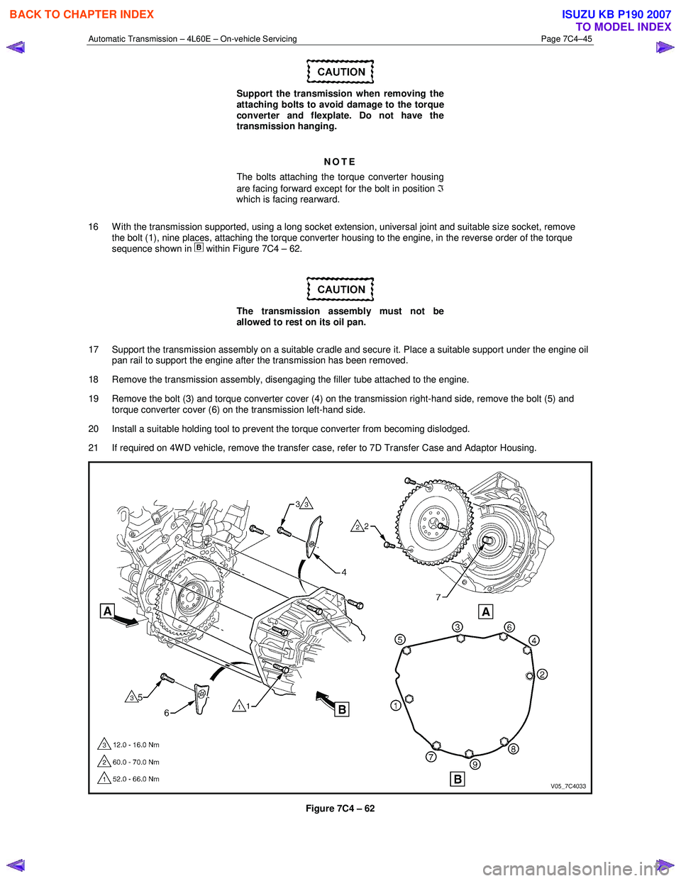
16 W ith the transmission supported, using a long socket extension, universal joint and suitable size socket, remove the bolt (1), nine places, attaching the torque converter housing to the engine, in the reverse order of the torque
sequence shown in
within Figure 7C4 – 62.
The transmission assembly must not be
allowed to rest on its oil pan.
17 Support the transmission assembly on a suitable cradle and secure it. Place a suitable support under the engine oil pan rail to support the engine after the transmission has been removed.
18 Remove the transmission assembly, disengaging the filler tube attached to the engine.
19 Remove the bolt (3) and torque converter cover (4) on the transmission right-hand side, remove the bolt (5) and torque converter cover (6) on the transmission left-hand side.
20 Install a suitable holding tool to prevent the torque converter from becoming dislodged.
21 If required on 4W D vehicle, remove the transfer case, refer to 7D Transfer Case and Adaptor Housing.
Figure 7C4 – 62
BACK TO CHAPTER INDEX
TO MODEL INDEX
ISUZU KB P190 2007
Page 3959 of 6020
Automatic Transmission – 4L60E – On-vehicle Servicing Page 7C4–46
Reinstall
1 If required on 4W D vehicle, reinstall the transfer case, refer to 7D Transfer Case and Adaptor Housing.
2 Ensure the transmission and the engine mating surfaces are clean and free of burrs.
3 Lubricate the torque converter spigot (7) with a small amount of high temperature wheel bearing grease, refer to Figure 7C4 – 62.
4 Install a new filler tube seal into the transmission case.
Support the transmission while installing the
attaching bolts to avoid damage to the torque
converter and flexplate. Do not have the
transmission hanging.
5 Bring the transmission up to the engine, inserting the filler tube and ensuring the locating dowels completely enter the torque converter housing.
6 Reconnect the breather hose to the top of the transmission case.
NOTE
The bolts attaching the torque converter housing
are facing forward except for the bolt in position ℑ
which is facing rearward.
7 With the transmission supported, install the bolt (1), nine places, attaching the torque converter housing to the engine and tighten to the correct torque specification following the sequence shown in
within Figure 7C4 – 62.
Torque converter housing attaching
bolt torque specification .......................... 52.0 – 66.0 Nm
8 Remove the access hole cover plate from the lower surface of the housing and push the torque converter forward to meet the flexplate, then hand start three new bolts (2) before tightening to the correct torque specification.
Reinstall the access hole cover plate.
Torque converter to flexplate attaching
bolt torque specification .......................... 60.0 – 70.0 Nm
9 Reinstall the bolt (3) and torque converter cover (4) on the transmission right-hand side and the bolt (5) and torque converter cover (6) on the transmission left-hand side, tighten the bolts to the correct torque specification.
Torque converter cover attaching
bolt torque specification .......................... 12.0 – 16.0 Nm
10 Reinstall the transmission fluid lines, refer to 3.17 Transmission Cooler Line/Hose Assemblies.
Prior to connecting the harness connector to
the transmission, check that all pins and
seals are in sound condition and the dust
boot is not torn or damaged.
11 Reconnect the transmission harness connector to the transmission as follows: a Push straight down on the connector body until a click is heard.
b Reinstall the dust boot ensuring it is correctly located.
12 Attach the harness clips to the right-hand and left-hand sides of the transmission case, refer to 12O Fuses, Relays and Wiring Harnesses.
13 On 4WD vehicle, connect the harness two clips from the upper side of the transfer case.
BACK TO CHAPTER INDEX
TO MODEL INDEX
ISUZU KB P190 2007
Page 3960 of 6020
Automatic Transmission – 4L60E – On-vehicle Servicing Page 7C4–47
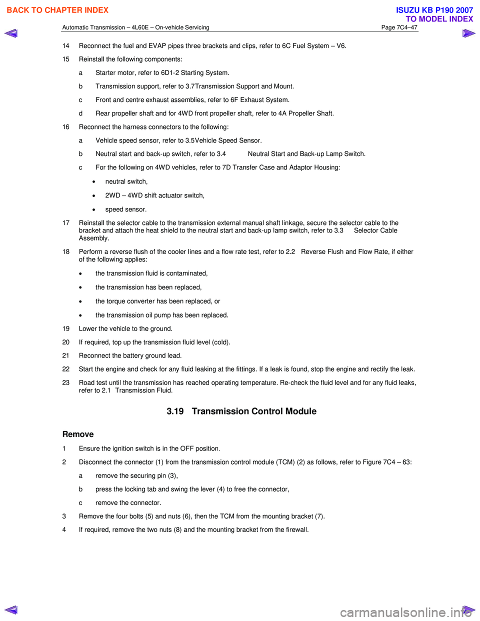
14 Reconnect the fuel and EVAP pipes three brackets and clips, refer to 6C Fuel System – V6.
15 Reinstall the following components:
a Starter motor, refer to 6D1-2 Starting System.
b Transmission support, refer to 3.7 Transmission Support and Mount.
c Front and centre exhaust assemblies, refer to 6F Exhaust System.
d Rear propeller shaft and for 4WD front propeller shaft, refer to 4A Propeller Shaft.
16 Reconnect the harness connectors to the following: a Vehicle speed sensor, refer to 3.5 Vehicle Speed Sensor.
b Neutral start and back-up switch, refer to 3.4 Neutral Start and Back-up Lamp Switch.
c For the following on 4W D vehicles, refer to 7D Transfer Case and Adaptor Housing:
• neutral switch,
• 2WD – 4WD shift actuator switch,
• speed sensor.
17 Reinstall the selector cable to the transmission external manual shaft linkage, secure the selector cable to the bracket and attach the heat shield to the neutral start and back-up lamp switch, refer to 3.3 Selector Cable
Assembly.
18 Perform a reverse flush of the cooler lines and a flow rate test, refer to 2.2 Reverse Flush and Flow Rate, if either of the following applies:
• the transmission fluid is contaminated,
• the transmission has been replaced,
• the torque converter has been replaced, or
• the transmission oil pump has been replaced.
19 Lower the vehicle to the ground.
20 If required, top up the transmission fluid level (cold).
21 Reconnect the battery ground lead.
22 Start the engine and check for any fluid leaking at the fittings. If a leak is found, stop the engine and rectify the leak.
23 Road test until the transmission has reached operating temperature. Re-check the fluid level and for any fluid leaks, refer to 2.1 Transmission Fluid.
3.19 Transmission Control Module
Remove
1 Ensure the ignition switch is in the OFF position.
2 Disconnect the connector (1) from the transmission control module (TCM) (2) as follows, refer to Figure 7C4 – 63: a remove the securing pin (3),
b press the locking tab and swing the lever (4) to free the connector,
c remove the connector.
3 Remove the four bolts (5) and nuts (6), then the TCM from the mounting bracket (7).
4 If required, remove the two nuts (8) and the mounting bracket from the firewall.
BACK TO CHAPTER INDEX
TO MODEL INDEX
ISUZU KB P190 2007
Page 3968 of 6020
7A2-2 TRANSMISSION CONTROL SYSTEM (AW30–40LE)
Service Precaution
WARNING: THIS VEHICLE HAS A SUPPLEMENTAL
RESTRAINT SYSTEM (SRS). REFER TO THE SRS
COMPONENT AND WIRING LOCATION VIEW IN
ORDER TO DETERMINE WHETHER YOU ARE
PERFORMING SERVICE ON OR NEAR THE SRS
COMPONENTS OR THE SRS WIRING. WHEN YOU
ARE PERFORMING SERVICE ON OR NEAR THE
SRS COMPONENTS OR THE SRS WIRING, REFER
TO THE SRS SERVICE INFORMATION. FAILURE TO
FOLLOW WARNINGS COULD RESULT IN
POSSIBLE AIR BAG DEPLOYMENT, PERSONAL
INJURY, OR OTHERWISE UNNEEDED SRS SYSTEM
REPAIRS.
CAUTION: Always use the correct fastener in the
proper location. When you replace a fastener, use
ONLY the exact part number for that application.
ISUZU will call out those fasteners that require a
replacement after removal. ISUZU will also call out
the fasteners that require thread lockers or thread
sealant. UNLESS OTHERWISE SPECIFIED, do not
use supplemental coatings (Paints, greases, o
r
other corrosion inhibitors) on threaded fasteners or
fastener joint interfaces. Generally, such coatings
adversely affect the fastener torque and the joint
clamping force, and may damage the fastener.
When you install fasteners, use the correct
tightening sequence and specifications. Following
these instructions can help you avoid damage to
parts and systems.
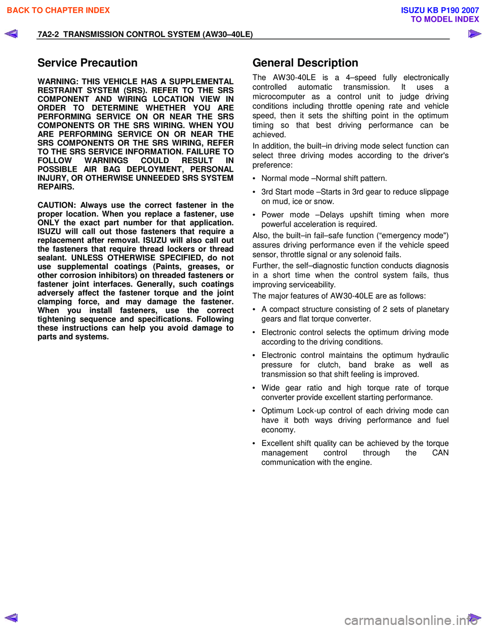
General Description
The AW 30-40LE is a 4–speed fully electronically
controlled automatic transmission. It uses a
microcomputer as a control unit to judge driving
conditions including throttle opening rate and vehicle
speed, then it sets the shifting point in the optimum
timing so that best driving performance can be
achieved.
In addition, the built–in driving mode select function can
select three driving modes according to the driver's
preference:
• Normal mode –Normal shift pattern.
• 3rd Start mode –Starts in 3rd gear to reduce slippage
on mud, ice or snow.
• Power mode –Delays upshift timing when more
powerful acceleration is required.
Also, the built–in fail–safe function (“emergency mode")
assures driving performance even if the vehicle speed
sensor, throttle signal or any solenoid fails.
Further, the self–diagnostic function conducts diagnosis
in a short time when the control system fails, thus
improving serviceability.
The major features of AW 30-40LE are as follows:
•
A compact structure consisting of 2 sets of planetary
gears and flat torque converter.
• Electronic control selects the optimum driving mode according to the driving conditions.
• Electronic control maintains the optimum hydraulic
pressure for clutch, band brake as well as
transmission so that shift feeling is improved.
• W ide gear ratio and high torque rate of torque
converter provide excellent starting performance.
• Optimum Lock-up control of each driving mode can
have it both ways driving performance and fuel
economy.
• Excellent shift quality can be achieved by the torque
management control through the CAN
communication with the engine.
BACK TO CHAPTER INDEX
TO MODEL INDEX
ISUZU KB P190 2007
Page 3975 of 6020
TRANSMISSION CONTROL SYSTEM (AW30–40LE) 7A2-9
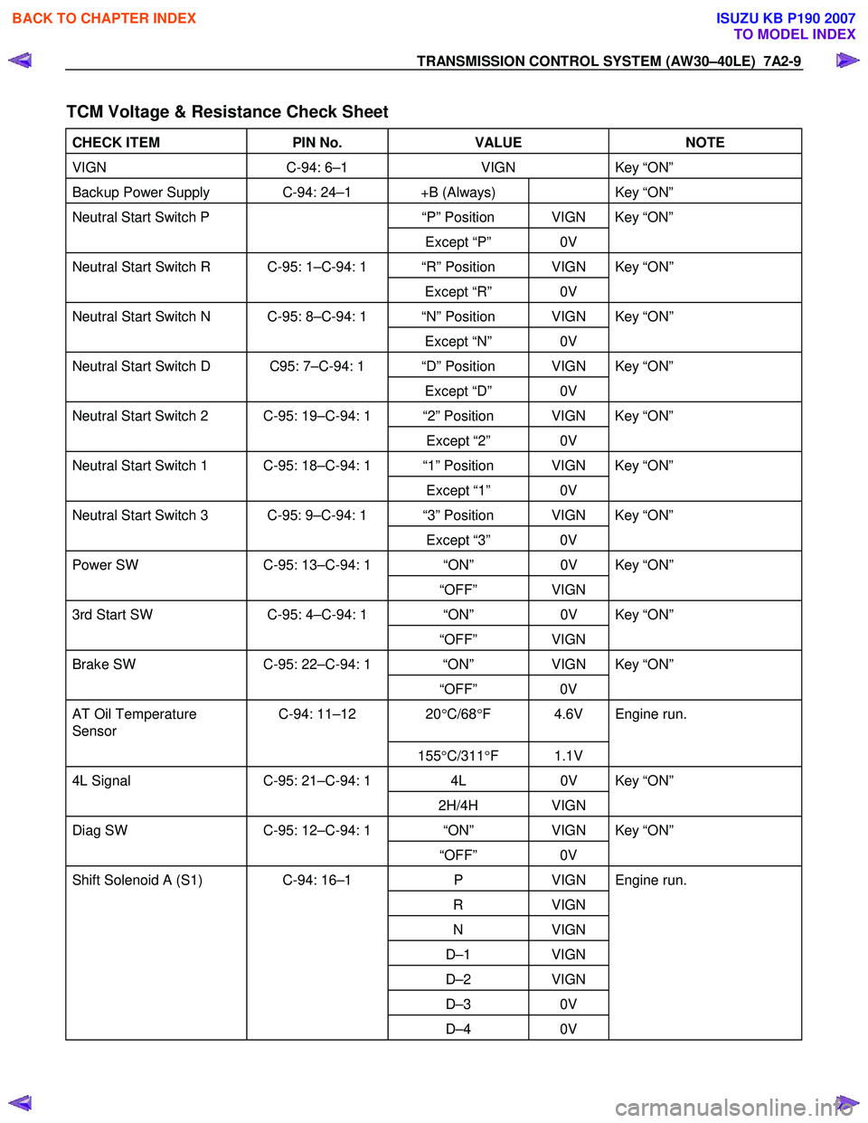
TCM Voltage & Resistance Check Sheet
CHECK ITEM PIN No. VALUE NOTE
VIGN C-94: 6–1 VIGN Key “ON”
Backup Power Supply C-94: 24–1 +B (Always) Key “ON”
Neutral Start Switch P “P” Position VIGN Key “ON”
Except “P” 0V
Neutral Start Switch R C-95: 1–C-94: 1 “R” Position VIGN Key “ON”
Except “R” 0V
Neutral Start Switch N C-95: 8–C-94: 1 “N” Position VIGN Key “ON”
Except “N” 0V
Neutral Start Switch D C95: 7–C-94: 1 “D” Position VIGN Key “ON”
Except “D” 0V
Neutral Start Switch 2 C-95: 19–C-94: 1 “2” Position VIGN Key “ON”
Except “2” 0V
Neutral Start Switch 1 C-95: 18–C-94: 1 “1” Position VIGN Key “ON”
Except “1” 0V
Neutral Start Switch 3 C-95: 9–C-94: 1 “3” Position VIGN Key “ON”
Except “3” 0V
Power SW C-95: 13–C-94: 1 “ON” 0V Key “ON”
“OFF” VIGN
3rd Start SW C-95: 4–C-94: 1 “ON” 0V Key “ON”
“OFF” VIGN
Brake SW C-95: 22–C-94: 1 “ON” VIGN Key “ON”
“OFF” 0V
AT Oil Temperature
Sensor C-94: 11–12 20
°C/68 °F 4.6V Engine run.
155°C/311 °F 1.1V
4L Signal C-95: 21–C-94: 1 4L 0V Key “ON”
2H/4H VIGN
Diag SW C-95: 12–C-94: 1 “ON” VIGN Key “ON”
“OFF” 0V
Shift Solenoid A (S1) C-94: 16–1 P VIGN Engine run.
R VIGN
N VIGN
D–1 VIGN
D–2 VIGN
D–3 0V
D–4 0V
BACK TO CHAPTER INDEX
TO MODEL INDEX
ISUZU KB P190 2007
Page 3976 of 6020
7A2-10 TRANSMISSION CONTROL SYSTEM (AW30–40LE)
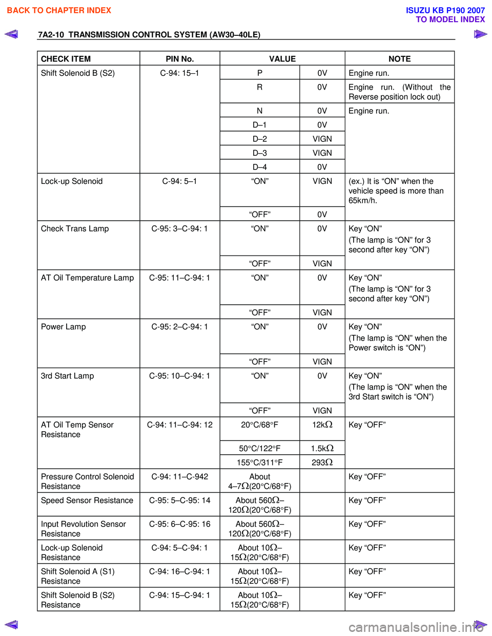
CHECK ITEM PIN No. VALUE NOTE
Shift Solenoid B (S2) C-94: 15–1 P 0V Engine run.
R 0V Engine run. (W ithout the
Reverse position lock out)
N 0V Engine run.
D–1 0V
D–2 VIGN
D–3 VIGN
D–4 0V
Lock-up Solenoid C-94: 5–1 “ON” VIGN (ex.) It is “ON” when the
vehicle speed is more than
65km/h.
“OFF” 0V
Check Trans Lamp C-95: 3–C-94: 1 “ON” 0V Key “ON”
(The lamp is “ON” for 3
second after key “ON”)
“OFF” VIGN
AT Oil Temperature Lamp C-95: 11–C-94: 1 “ON” 0V Key “ON”
(The lamp is “ON” for 3
second after key “ON”)
“OFF” VIGN
Power Lamp C-95: 2–C-94: 1 “ON” 0V Key “ON”
(The lamp is “ON” when the
Power switch is “ON”)
“OFF” VIGN
3rd Start Lamp C-95: 10–C-94: 1 “ON” 0V Key “ON”
(The lamp is “ON” when the
3rd Start switch is “ON”)
“OFF” VIGN
AT Oil Temp Sensor
Resistance C-94: 11–C-94: 12 20
°C/68 °F 12kΩ Key “OFF”
50°C/122 °F 1.5kΩ
155°C/311 °F 293Ω
Pressure Control Solenoid
Resistance C-94: 11–C-942 About
4–7
Ω(20 °C/68 °F)
Key “OFF”
Speed Sensor Resistance C-95: 5–C-95: 14 About 560Ω–
120
Ω(20 °C/68 °F)
Key “OFF”
Input Revolution Sensor
Resistance C-95: 6–C-95: 16 About 560Ω–
120
Ω(20 °C/68 °F)
Key “OFF”
Lock-up Solenoid
Resistance C-94: 5–C-94: 1 About 10Ω–
15
Ω(20 °C/68 °F)
Key “OFF”
Shift Solenoid A (S1)
Resistance C-94: 16–C-94: 1 About 10Ω–
15
Ω(20 °C/68 °F)
Key “OFF”
Shift Solenoid B (S2)
Resistance C-94: 15–C-94: 1 About 10Ω–
15
Ω(20 °C/68 °F)
Key “OFF”
BACK TO CHAPTER INDEX
TO MODEL INDEX
ISUZU KB P190 2007