Page 4020 of 6020
7A2-54 TRANSMISSION CONTROL SYSTEM (AW30–40LE)
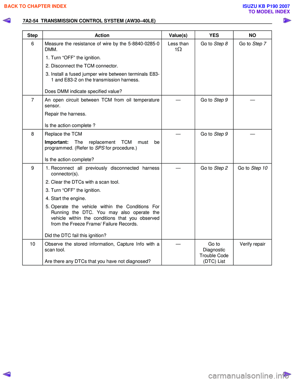
Step Action Value(s) YES NO
6 Measure the resistance of wire by the 5-8840-0285-0
DMM.
1. Turn “OFF” the ignition.
2. Disconnect the TCM connector.
3. Install a fused jumper wire between terminals E83-
1 and E83-2 on the transmission harness.
Does DMM indicate specified value? Less than
1
Ω
Go to Step 8 Go to Step 7
7 An open circuit between TCM from oil temperature
sensor.
Repair the harness.
Is the action complete ? — Go to
Step 9 —
8 Replace the TCM
Important: The replacement TCM must be
programmed. (Refer to SPS for procedure.)
Is the action complete? — Go to
Step 9 —
9 1. Reconnect all previously disconnected harness
connector(s).
2. Clear the DTCs with a scan tool.
3. Turn “OFF” the ignition.
4. Start the engine.
5. Operate the vehicle within the Conditions For Running the DTC. You may also operate the
vehicle within the conditions that you observed
from the Freeze Frame/ Failure Records.
Did the DTC fail this ignition? — Go to
Step 2 Go to Step 10
10 Observe the stored information, Capture Info with a
scan tool.
Are there any DTCs that you have not diagnosed? — Go
to
Diagnostic
Trouble Code (DTC) List Verify repair
BACK TO CHAPTER INDEX
TO MODEL INDEX
ISUZU KB P190 2007
Page 4021 of 6020
TRANSMISSION CONTROL SYSTEM (AW30–40LE) 7A2-55
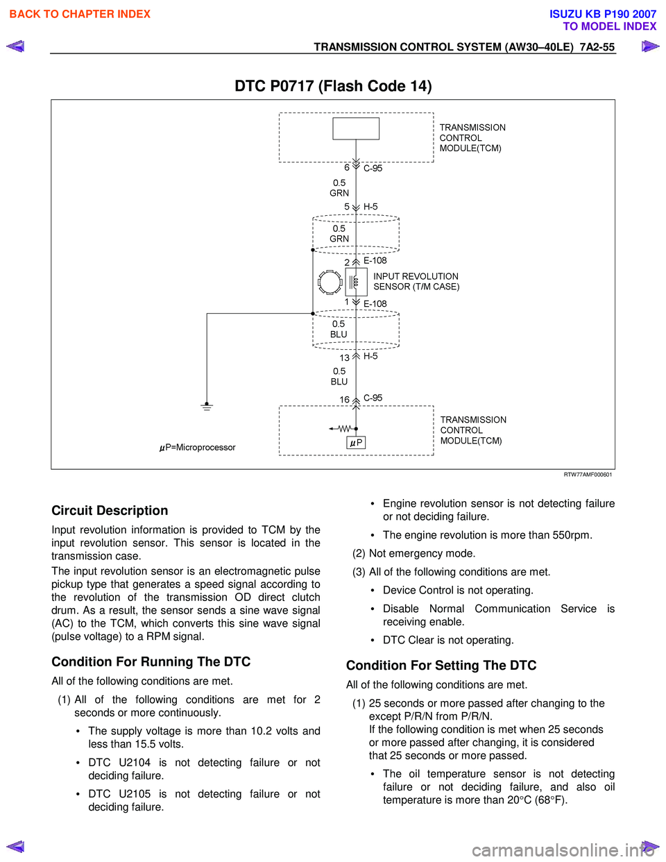
DTC P0717 (Flash Code 14)
RTW 77AMF000601
Circuit Description
Input revolution information is provided to TCM by the
input revolution sensor. This sensor is located in the
transmission case.
The input revolution sensor is an electromagnetic pulse
pickup type that generates a speed signal according to
the revolution of the transmission OD direct clutch
drum. As a result, the sensor sends a sine wave signal
(AC) to the TCM, which converts this sine wave signal
(pulse voltage) to a RPM signal.
Condition For Running The DTC
All of the following conditions are met.
(1)
All of the following conditions are met for 2
seconds or more continuously.
• The supply voltage is more than 10.2 volts and
less than 15.5 volts.
• DTC U2104 is not detecting failure or not
deciding failure.
• DTC U2105 is not detecting failure or not
deciding failure.
• Engine revolution sensor is not detecting failure
or not deciding failure.
• The engine revolution is more than 550rpm.
(2) Not emergency mode.
(3) All of the following conditions are met. • Device Control is not operating.
• Disable Normal Communication Service is
receiving enable.
• DTC Clear is not operating.
Condition For Setting The DTC
All of the following conditions are met.
(1) 25 seconds or more passed after changing to the except P/R/N from P/R/N.
If the following condition is met when 25 seconds
or more passed after changing, it is considered
that 25 seconds or more passed.
• The oil temperature sensor is not detecting
failure or not deciding failure, and also oil
temperature is more than 20 °C (68 °F).
BACK TO CHAPTER INDEX
TO MODEL INDEX
ISUZU KB P190 2007
Page 4023 of 6020
TRANSMISSION CONTROL SYSTEM (AW30–40LE) 7A2-57
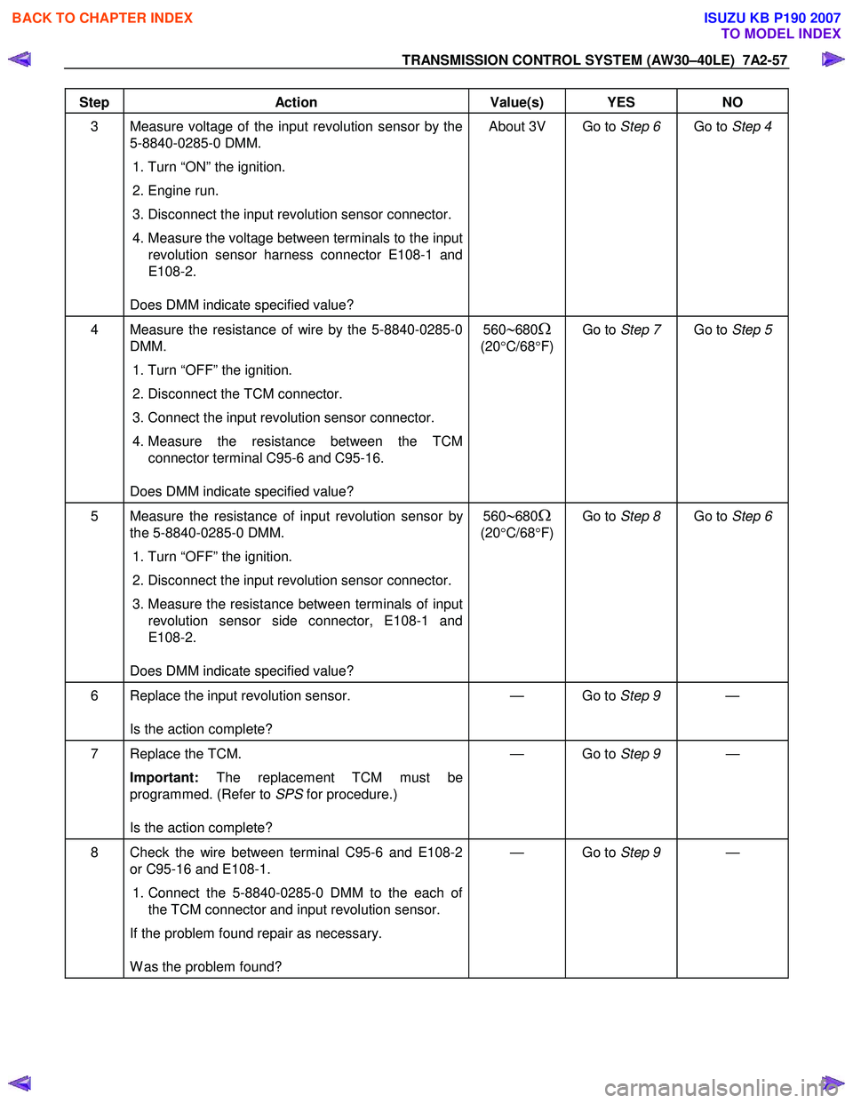
Step Action Value(s) YES NO
3 Measure voltage of the input revolution sensor by the
5-8840-0285-0 DMM.
1. Turn “ON” the ignition.
2. Engine run.
3. Disconnect the input revolution sensor connector.
4. Measure the voltage between terminals to the input
revolution sensor harness connector E108-1 and
E108-2.
Does DMM indicate specified value? About 3V Go to
Step 6 Go to Step 4
4 Measure the resistance of wire by the 5-8840-0285-0
DMM.
1. Turn “OFF” the ignition.
2. Disconnect the TCM connector.
3. Connect the input revolution sensor connector.
4. Measure the resistance between the TCM
connector terminal C95-6 and C95-16.
Does DMM indicate specified value? 560∼680Ω
(20 °C/68 °F) Go to
Step 7 Go to Step 5
5 Measure the resistance of input revolution sensor by
the 5-8840-0285-0 DMM.
1. Turn “OFF” the ignition.
2. Disconnect the input revolution sensor connector.
3. Measure the resistance between terminals of input
revolution sensor side connector, E108-1 and
E108-2.
Does DMM indicate specified value? 560∼680Ω
(20 °C/68 °F) Go to
Step 8 Go to Step 6
6 Replace the input revolution sensor.
Is the action complete? — Go to
Step 9 —
7 Replace the TCM.
Important: The replacement TCM must be
programmed. (Refer to SPS for procedure.)
Is the action complete? — Go to
Step 9 —
8 Check the wire between terminal C95-6 and E108-2
or C95-16 and E108-1.
1. Connect the 5-8840-0285-0 DMM to the each of
the TCM connector and input revolution sensor.
If the problem found repair as necessary.
W as the problem found? — Go to
Step 9 —
BACK TO CHAPTER INDEX
TO MODEL INDEX
ISUZU KB P190 2007
Page 4024 of 6020
7A2-58 TRANSMISSION CONTROL SYSTEM (AW30–40LE)
Step Action Value(s) YES NO
9 1. Reconnect all previously disconnected harness
connector(s).
2. Clear the DTCs with a scan tool.
3. Turn “OFF” the ignition.
4. Start the engine.
5. Operate the vehicle within the Conditions For Running the DTC. You may also operate the
vehicle within the conditions that you observed
from the Freeze Frame/ Failure Records.
Did the DTC fail this ignition? — Go to
Step 2 Go to Step 10
10 Observe the stored information, Capture Info with a
scan tool.
Are there any DTCs that you have not diagnosed? — Go
to
Diagnostic
Trouble Code (DTC) List Verify repair
BACK TO CHAPTER INDEX
TO MODEL INDEX
ISUZU KB P190 2007
Page 4025 of 6020
TRANSMISSION CONTROL SYSTEM (AW30–40LE) 7A2-59
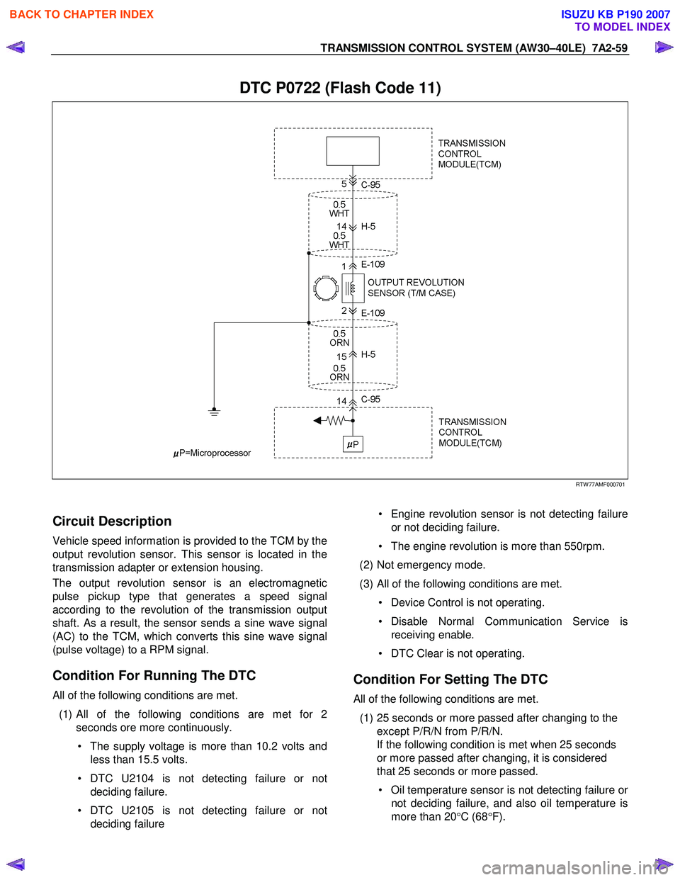
DTC P0722 (Flash Code 11)
RTW 77AMF000701
Circuit Description
Vehicle speed information is provided to the TCM by the
output revolution sensor. This sensor is located in the
transmission adapter or extension housing.
The output revolution sensor is an electromagnetic
pulse pickup type that generates a speed signal
according to the revolution of the transmission output
shaft. As a result, the sensor sends a sine wave signal
(AC) to the TCM, which converts this sine wave signal
(pulse voltage) to a RPM signal.
Condition For Running The DTC
All of the following conditions are met.
(1)
All of the following conditions are met for 2
seconds ore more continuously.
• The supply voltage is more than 10.2 volts and less than 15.5 volts.
• DTC U2104 is not detecting failure or not deciding failure.
• DTC U2105 is not detecting failure or not deciding failure
• Engine revolution sensor is not detecting failure
or not deciding failure.
• The engine revolution is more than 550rpm.
(2) Not emergency mode.
(3) All of the following conditions are met. • Device Control is not operating.
• Disable Normal Communication Service is receiving enable.
• DTC Clear is not operating.
Condition For Setting The DTC
All of the following conditions are met.
(1) 25 seconds or more passed after changing to the except P/R/N from P/R/N.
If the following condition is met when 25 seconds
or more passed after changing, it is considered
that 25 seconds or more passed.
• Oil temperature sensor is not detecting failure o
r
not deciding failure, and also oil temperature is
more than 20 °C (68 °F).
BACK TO CHAPTER INDEX
TO MODEL INDEX
ISUZU KB P190 2007
Page 4027 of 6020
TRANSMISSION CONTROL SYSTEM (AW30–40LE) 7A2-61
Step Action Value(s) YES NO
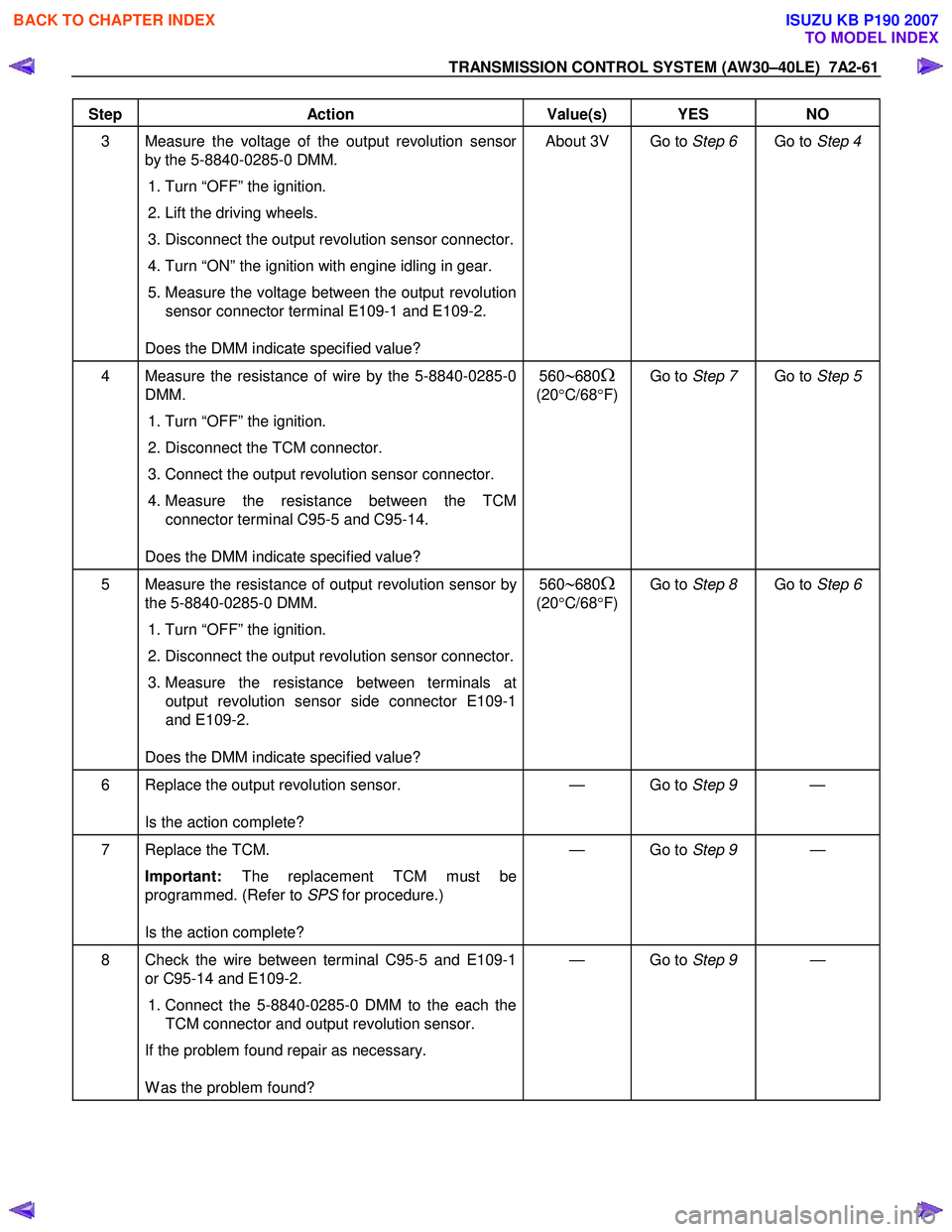
3 Measure the voltage of the output revolution sensor
by the 5-8840-0285-0 DMM.
1. Turn “OFF” the ignition.
2. Lift the driving wheels.
3. Disconnect the output revolution sensor connector.
4. Turn “ON” the ignition with engine idling in gear.
5. Measure the voltage between the output revolution sensor connector terminal E109-1 and E109-2.
Does the DMM indicate specified value? About 3V Go to
Step 6 Go to Step 4
4 Measure the resistance of wire by the 5-8840-0285-0
DMM.
1. Turn “OFF” the ignition.
2. Disconnect the TCM connector.
3. Connect the output revolution sensor connector.
4. Measure the resistance between the TCM
connector terminal C95-5 and C95-14.
Does the DMM indicate specified value? 560∼680Ω
(20
°C/68 °F) Go to
Step 7 Go to Step 5
5 Measure the resistance of output revolution sensor by
the 5-8840-0285-0 DMM.
1. Turn “OFF” the ignition.
2. Disconnect the output revolution sensor connector.
3. Measure the resistance between terminals at
output revolution sensor side connector E109-1
and E109-2.
Does the DMM indicate specified value? 560∼680Ω
(20
°C/68 °F) Go to
Step 8 Go to Step 6
6 Replace the output revolution sensor.
Is the action complete? — Go to
Step 9 —
7 Replace the TCM.
Important: The replacement TCM must be
programmed. (Refer to SPS for procedure.)
Is the action complete? — Go to
Step 9 —
8 Check the wire between terminal C95-5 and E109-1
or C95-14 and E109-2.
1. Connect the 5-8840-0285-0 DMM to the each the
TCM connector and output revolution sensor.
If the problem found repair as necessary.
W as the problem found? — Go to
Step 9 —
BACK TO CHAPTER INDEX
TO MODEL INDEX
ISUZU KB P190 2007
Page 4028 of 6020
7A2-62 TRANSMISSION CONTROL SYSTEM (AW30–40LE)
Step Action Value(s) YES NO
9 1. Reconnect all previously disconnected harness
connector(s).
2. Clear the DTCs with a scan tool.
3. Turn “OFF” the ignition.
4. Start the engine.
5. Operate the vehicle within the Conditions For Running the DTC. You may also operate the
vehicle within the conditions that you observed
from the Freeze Frame/ Failure Records.
Did the DTC fail this ignition? — Go to
Step 2 Go to Step 10
10 Observe the stored information, Capture Info with a
scan tool.
Are there any DTCs that you have not diagnosed? — Go
to
Diagnostic
Trouble Code (DTC) List Verify repair
BACK TO CHAPTER INDEX
TO MODEL INDEX
ISUZU KB P190 2007
Page 4029 of 6020
TRANSMISSION CONTROL SYSTEM (AW30–40LE) 7A2-63
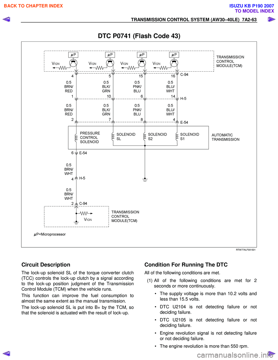
DTC P0741 (Flash Code 43)
RTW 77ALF001501
Circuit Description
The lock-up solenoid SL of the torque converter clutch
(TCC) controls the lock-up clutch by a signal according
to the lock-up position judgment of the Transmission
Control Module (TCM) when the vehicle runs.
This function can improve the fuel consumption to
almost the same extent as the manual transmission.
The lock-up solenoid SL is put into B+ by the TCM, so
that the solenoid is actuated with the result of lock-up.
Condition For Running The DTC
All of the following conditions are met.
(1)
All of the following conditions are met for 2
seconds or more continuously.
• The supply voltage is more than 10.2 volts and less than 15.5 volts.
• DTC U2104 is not detecting failure or not deciding failure.
• DTC U2105 is not detecting failure or not deciding failure.
• Engine revolution signal is not detecting failure or not deciding failure.
• The engine revolution is more than 550 rpm.
BACK TO CHAPTER INDEX
TO MODEL INDEX
ISUZU KB P190 2007