2007 ISUZU KB P190 Harness
[x] Cancel search: HarnessPage 1563 of 6020

6C-22 FUEL SYSTEM (4JK1/4JJ1)
Removal
1. Remove the starter motor.
• Refer to the removal procedure for engine
electricals in this manual.
2. Remove the fuel feed pipe (1) for supply pump.
Note: Cover the areas exposed during parts removal to
prevent the entry of foreign material into the fuel
system.
RTW 76CSH000501
3. Remove the fuel hose (1).
Note: Cover the areas exposed during parts removal to
prevent the entry of foreign material into the fuel
system.
RTW 76CSH000601
4. Remove the leak off pipe and hose (1).
Note: Cover the areas exposed during parts removal to
prevent the entry of foreign material into the fuel
system.
RTW 76CSH000301
5. Disconnect the fuel rail pressure sensor harness
connector (1).
LNW 76CSH001601
BACK TO CHAPTER INDEX
TO MODEL INDEX
ISUZU KB P190 2007
Page 1565 of 6020
6C-24 FUEL SYSTEM (4JK1/4JJ1)
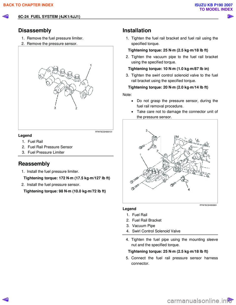
Disassembly
1. Remove the fuel pressure limiter.
2. Remove the pressure sensor.
RTW 76CSH000101
Legend
1. Fuel Rail
2. Fuel Rail Pressure Sensor
3. Fuel Pressure Limiter
Reassembly
1. Install the fuel pressure limiter.
Tightening torque: 172 N ⋅
⋅⋅
⋅
m (17.5 kg ⋅
⋅⋅
⋅
m/127 lb ft)
2. Install the fuel pressure sensor. Tightening torque: 98 N ⋅
⋅⋅
⋅
m (10.0 kg ⋅
⋅⋅
⋅
m/72 lb ft)
Installation
1. Tighten the fuel rail bracket and fuel rail using the
specified torque.
Tightening torque: 25 N ⋅
⋅⋅
⋅
m (2.5 kg ⋅
⋅⋅
⋅
m/18 lb ft)
2. Tighten the vacuum pipe to the fuel rail bracket using the specified torque.
Tightening torque: 10 N ⋅
⋅⋅
⋅
m (1.0 kg ⋅
⋅⋅
⋅
m/87 lb in)
3. Tighten the swirl control solenoid valve to the fuel rail bracket using the specified torque.
Tightening torque: 20 N ⋅
⋅⋅
⋅
m (2.0 kg ⋅
⋅⋅
⋅
m/14 lb ft)
Note: • Do not grasp the pressure sensor, during the
fuel rail removal procedure.
• Take care not to damage the connector unit o
f
the pressure sensor.
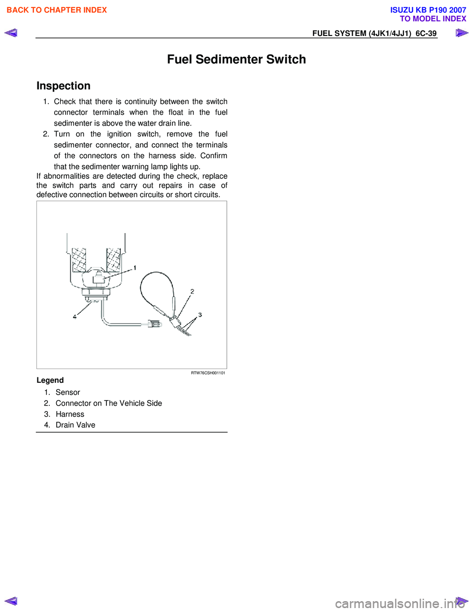
RTW 76CSH000801
Legend
1. Fuel Rail
2. Fuel Rail Bracket
3. Vacuum Pipe
4. Swirl Control Solenoid Valve
4. Tighten the fuel pipe using the mounting sleeve
nut and the specified torque.
Tightening torque: 25 N ⋅
⋅⋅
⋅
m (2.5 kg ⋅
⋅⋅
⋅
m/18 lb ft)
5. Connect the fuel rail pressure sensor harness connector.
BACK TO CHAPTER INDEX
TO MODEL INDEX
ISUZU KB P190 2007
Page 1580 of 6020
FUEL SYSTEM (4JK1/4JJ1) 6C-39
Fuel Sedimenter Switch
Inspection
1. Check that there is continuity between the switch
connector terminals when the float in the fuel
sedimenter is above the water drain line.
2. Turn on the ignition switch, remove the fuel sedimenter connector, and connect the terminals
of the connectors on the harness side. Confirm
that the sedimenter warning lamp lights up.
If abnormalities are detected during the check, replace
the switch parts and carry out repairs in case o
f
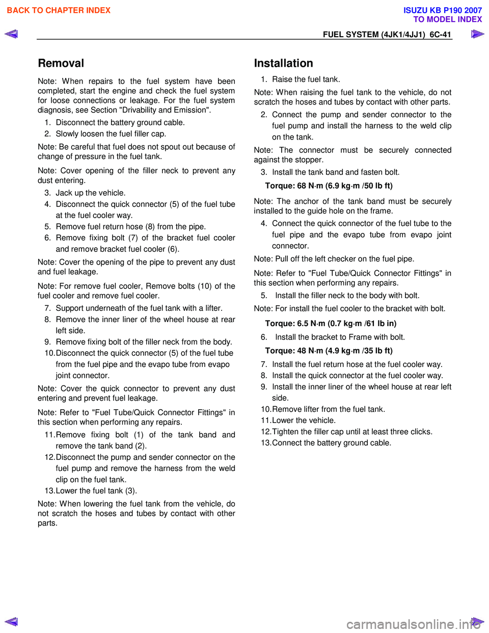
defective connection between circuits or short circuits.
RTW 76CSH001101
Legend
1. Sensor
2. Connector on The Vehicle Side
3. Harness
4. Drain Valve
BACK TO CHAPTER INDEX
TO MODEL INDEX
ISUZU KB P190 2007
Page 1582 of 6020
FUEL SYSTEM (4JK1/4JJ1) 6C-41
Removal
Note: W hen repairs to the fuel system have been
completed, start the engine and check the fuel system
for loose connections or leakage. For the fuel system
diagnosis, see Section "Drivability and Emission".
1. Disconnect the battery ground cable.
2. Slowly loosen the fuel filler cap.
Note: Be careful that fuel does not spout out because o
f
change of pressure in the fuel tank.
Note: Cover opening of the filler neck to prevent an
y
dust entering. 3. Jack up the vehicle.
4. Disconnect the quick connector (5) of the fuel tube at the fuel cooler way.
5. Remove fuel return hose (8) from the pipe.
6. Remove fixing bolt (7) of the bracket fuel coole
r
and remove bracket fuel cooler (6).
Note: Cover the opening of the pipe to prevent any dust
and fuel leakage.
Note: For remove fuel cooler, Remove bolts (10) of the
fuel cooler and remove fuel cooler.
7. Support underneath of the fuel tank with a lifter.
8. Remove the inner liner of the wheel house at rea
r
left side.
9. Remove fixing bolt of the filler neck from the body.
10. Disconnect the quick connector (5) of the fuel tube from the fuel pipe and the evapo tube from evapo
joint connector.
Note: Cover the quick connector to prevent any dust
entering and prevent fuel leakage.
Note: Refer to "Fuel Tube/Quick Connector Fittings" in
this section when performing any repairs.
11. Remove fixing bolt (1) of the tank band and remove the tank band (2).
12. Disconnect the pump and sender connector on the fuel pump and remove the harness from the weld
clip on the fuel tank.
13. Lower the fuel tank (3).
Note: W hen lowering the fuel tank from the vehicle, do
not scratch the hoses and tubes by contact with othe
r
parts.
Installation
1. Raise the fuel tank.
Note: W hen raising the fuel tank to the vehicle, do not
scratch the hoses and tubes by contact with other parts.
2. Connect the pump and sender connector to the fuel pump and install the harness to the weld clip
on the tank.
Note: The connector must be securely connected
against the stopper.
3. Install the tank band and fasten bolt.
Torque: 68 N ⋅
⋅⋅
⋅
m (6.9 kg ⋅
⋅⋅
⋅
m /50 lb ft)
Note: The anchor of the tank band must be securely
installed to the guide hole on the frame.
4. Connect the quick connector of the fuel tube to the fuel pipe and the evapo tube from evapo joint
connector.
Note: Pull off the left checker on the fuel pipe.
Note: Refer to "Fuel Tube/Quick Connector Fittings" in
this section when performing any repairs.
5. Install the filler neck to the body with bolt.
Note: For install the fuel cooler to the bracket with bolt.
Torque: 6.5 N ⋅
⋅⋅
⋅
m (0.7 kg ⋅
⋅⋅
⋅
m /61 lb in)
6. Install the bracket to Frame with bolt. Torque: 48 N ⋅
⋅⋅
⋅
m (4.9 kg ⋅
⋅⋅
⋅
m /35 lb ft)
7. Install the fuel return hose at the fuel cooler way.
8. Install the quick connector at the fuel cooler way.
9. Install the inner liner of the wheel house at rear left side.
10. Remove lifter from the fuel tank.
11. Lower the vehicle.
12. Tighten the filler cap until at least three clicks.
13. Connect the battery ground cable.
BACK TO CHAPTER INDEX
TO MODEL INDEX
ISUZU KB P190 2007
Page 1595 of 6020
ENGINE ELECTRICAL (4JK1/4JJ1) 6D-7
Diagnosis
On-vehicle Inspection
The charging system warning light tells the vehicle
operator of possible problems with the system.
W hen the ignition switch is moved to the ON position,
the light turns on. The light turns off immediately afte
r
the engine is started. If the light turns on during engine
operation, there is a problem with the charging system.
Perform the checks described below.
1. Check the belt (broken or loose).
2. Check the harness connectors (loose o
r
disconnected).
3. W ith the engine off, turn the ignition switch to the ON position. If the warning lamp does not light,
remove the harness connector from the generator.
Ground the connector IG terminal. The lamp
should light. If it does not, the bulb is burned out.
Replace the bulb.
4. Start the engine. If the warning lamp remains on, the generator must be repaired or replaced.
BACK TO CHAPTER INDEX
TO MODEL INDEX
ISUZU KB P190 2007
Page 1602 of 6020
6D-14 ENGINE ELECTRICAL (4JK1/4JJ1)
Reassembly
Follow the disassembly steps in reverse order to
reassemble the generator. Pay close attention to the
items below.
• Be very careful not to reverse battery polarity.
Reversed battery polarity will destroy the rectifie
r
diodes.
• Do not ground the generator B-terminal. Heat and
fire damage to the harness will result.
• If using a fast charge procedure, be sure to
disconnect the battery positive cable. If you do not,
the rectifier diodes will be exposed to high positive
voltage that will destroy them.
• Be very careful to reassemble the parts to thei
r
original positions. Particular care must be taken
with insulated parts.
• Carefully clean all insulated parts so that they are
completely free of oil and/or grease.
• Be sure that B-terminal twist-type stoppers (round
terminal) are securely inserted before tightening
the nuts.
Final Assembly
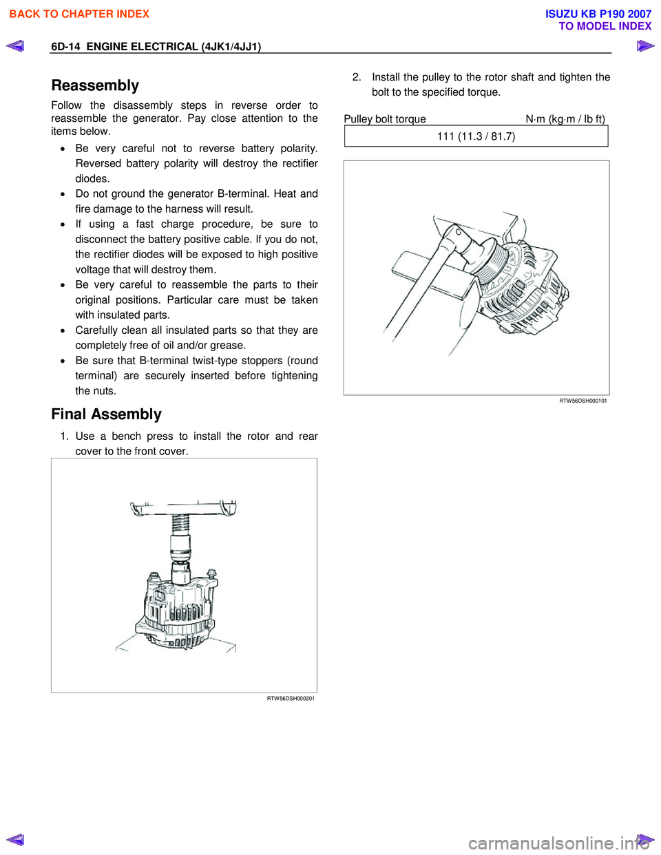
1. Use a bench press to install the rotor and rear
cover to the front cover.
RTW 56DSH000201
2. Install the pulley to the rotor shaft and tighten the
bolt to the specified torque.
Pulley bolt torque N
⋅m (kg⋅m / lb ft)
111 (11.3 / 81.7)
RTW 56DSH000101
BACK TO CHAPTER INDEX
TO MODEL INDEX
ISUZU KB P190 2007
Page 1662 of 6020
ENGINE CONTROL SYSTEM (4JK1/4JJ1) 6E-45
Diagnostic System Check - Engine Controls
Description
The Diagnostic System Check - Engine Controls is an
organized approach to identifying a condition that is
created by a malfunction in the electronic engine
control system. The Diagnostic System Check must be
the starting point for any driveability concern. The
Diagnostic System Check directs the service technician
to the next logical step in order to diagnose the
concern. Understanding and correctly using the
diagnostic table reduces diagnostic time, and prevents
the replacement of good parts.
Test Description
The numbers below refer to the step numbers on the
diagnostic table.
2. Lack of communication may be because of a partial
or a total malfunction of the serial data circuit.
7. The presence of DTCs which begin with U, indicate
that some other module is not communicating.
10. If there are other modules with DTCs set, refer to
the DTC list. The DTC list directs you to the appropriate
diagnostic procedure. If the control module stores
multiple DTCs, diagnose the DTCs in the following
order:
• Component level DTCs, such as sensor DTCs, solenoid DTCs, actuator DTCs, and relay DTCs.
Diagnose the multiple DTCs within this category in
numerical order. Begin with the lowest numbered
DTC, unless the diagnostic table directs you
otherwise. Diagnostic System Check Engine Controls
Important:
• DO NOT perform this diagnostic if there is not a driveability concern, unless another procedure
directs you to this diagnostic.
• Before you proceed with diagnosis, search for applicable service bulletins.
• Unless a diagnostic procedure instructs you, DO NOT clear the DTCs.
• If there is a condition with the starting system, refer to the starting system section in the engine
mechanical.
• Ensure the battery has a full charge.
• Ensure the battery cables (+) (-) are clean and tight.
• Ensure the ECM grounds are clean, tight, and in the correct location.
• Ensure the ECM harness connectors are clean and correctly connected. DO NOT attempt to
crank the engine with ECM harness connectors
disconnect.
• Ensure the ECM terminals are clean and correctly mating.
• Ensure the fuel injector ID code data is correctly programmed in to the ECM.
• Ensure the immobilizer security information is correctly programmed into the ECM and
immobilizer control unit (ICU).
• If there are fuel system DTC’s (P0087, P0088, P0089, P0093, P1093 or P1094), diagnose sensor
DTCs, solenoid DTCs, actuator DTCs and relay
DTCs first.
Diagnostic System Check - Engine Controls
Step Action Value(s)Yes No
1 Install a scan tool.
Does the scan tool turn ON? —
Go to Step 2 Go to Scan Tool
Does Not Power Up
2 1. Turn ON the ignition, with the engine OFF.
2. Attempt to establish communication with the listed control modules.
•ECM
• Immobilizer control unit (ICU) (If so equipped)
• Transmission control module (TCM) (AISIN A/T only)
Does the scan tool communicate with all the listed
control modules? —
Go to Step 3 Go to Scan Tool
Does Not
Communicate with CAN Device
BACK TO CHAPTER INDEX
TO MODEL INDEX
ISUZU KB P190 2007
Page 1675 of 6020
6E-58 ENGINE CONTROL SYSTEM (4JK1/4JJ1)
71. Inspect for an intermittent, for poor
connections and for corrosion at the data link
connector (DLC) (pins 6 and 14 of B-58).
2. Repair the connection(s) as necessary.
Did you find and correct the condition? —
Go to Step 19 Go to Step 8
8 Notice:
If no data recording module (DRM) is
installed, skip to Step 9.
1. Turn OFF the ignition.
2. Disconnect the DRM C-139 harness connector.
3. Turn ON the ignition, with the engine OFF.
4. Attempt to communicate with the ECM, TCM and ICU.
Does the scan tool communicate with the ECM,
TCM and ICU? —
Go to Step 14 Go to Step 9
9 1. Turn OFF the ignition.
2. Reconnect the DRM harness connector if disconnected.
3. Disconnect the ECM J1 (E-90) and J2 (C-58) harness connectors.
4. Turn ON the ignition, with the engine OFF.
5. Attempt to communicate with the TCM and ICU.
Does the scan tool communicate with the TCM and
ICU? —
Go to Step 15 Go to Step 10
10 Notice:
If no AISIN automatic transmission is
installed, skip to Step 11.
1. Turn OFF the ignition.
2. Reconnect the ECM J1 (E-90) and J2 (C-58) harness connectors.
3. Disconnect the TCM C-94 and C-95 harness connectors.
4. Turn ON the ignition, with the engine OFF.
5. Attempt to communicate with the ECM and ICU.
Does the scan tool communicate with the ECM and
ICU? —
Go to Step 16 Go to Step 11
11 Notice:
If no immobilizer system is installed, skip to
St ep 1 2.
1. Turn OFF the ignition.
2. Reconnect the ECM J1 (E-90) and J2 (C-58) harness connectors if disconnected.
3. Reconnect the TCM C-94 and C-95 harness connectors if disconnected.
4. Disconnect the ICU B-68 harness connector.
5. Turn ON the ignition, with the engine OFF.
6. Attempt to communicate with the ECM and TCM.
Does the scan tool communicate with the ECM and
TCM? —
Go to Step 17 Go to Step 13
Step
Action Value(s)Yes No
BACK TO CHAPTER INDEX
TO MODEL INDEX
ISUZU KB P190 2007