Page 1522 of 6020
6A-162 ENGINE MECHANICAL (4JK1/4JJ1)
Removal
1. Remove the oil pressure SW .
2. Remove the nipple; oil gallery.
3. Remove the nipple; oil pressure warning SW and gasket.
Inspection
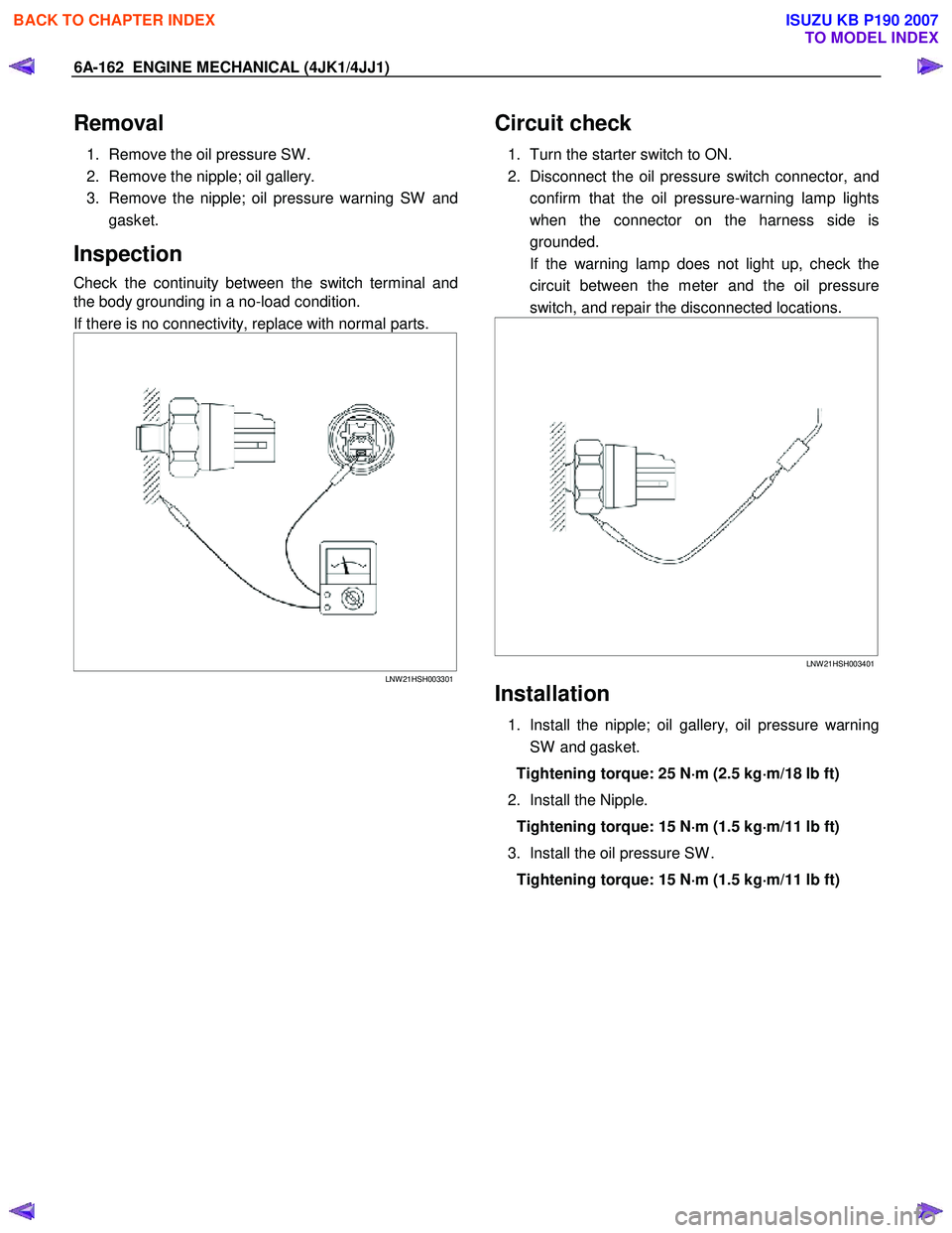
Check the continuity between the switch terminal and
the body grounding in a no-load condition.
If there is no connectivity, replace with normal parts.
LNW 21HSH003301
Circuit check
1. Turn the starter switch to ON.
2. Disconnect the oil pressure switch connector, and confirm that the oil pressure-warning lamp lights
when the connector on the harness side is
grounded.
If the warning lamp does not light up, check the circuit between the meter and the oil pressure
switch, and repair the disconnected locations.
LNW 21HSH003401
Installation
1. Install the nipple; oil gallery, oil pressure warning
SW and gasket.
Tightening torque: 25 N ⋅
⋅⋅
⋅
m (2.5 kg ⋅
⋅⋅
⋅
m/18 lb ft)
2. Install the Nipple. Tightening torque: 15 N ⋅
⋅⋅
⋅
m (1.5 kg ⋅
⋅⋅
⋅
m/11 lb ft)
3. Install the oil pressure SW . Tightening torque: 15 N ⋅
⋅⋅
⋅
m (1.5 kg ⋅
⋅⋅
⋅
m/11 lb ft)
BACK TO CHAPTER INDEX
TO MODEL INDEX
ISUZU KB P190 2007
Page 1534 of 6020
ENGINE COOLING (4JK1/4JJ1) 6B-11
Thermostat
Read this Section carefully before performing any
removal and installation procedure. This Section gives
you important points as well as the order of operation.
Be sure that you understand everything in this Section
before you begin.
Removal
1. Remove the engine cover.
2. Radiator Upper Hose a. Partially drain the engine coolant.
b. Remove the radiator upper hose.
c. Remove the engine harness clip.
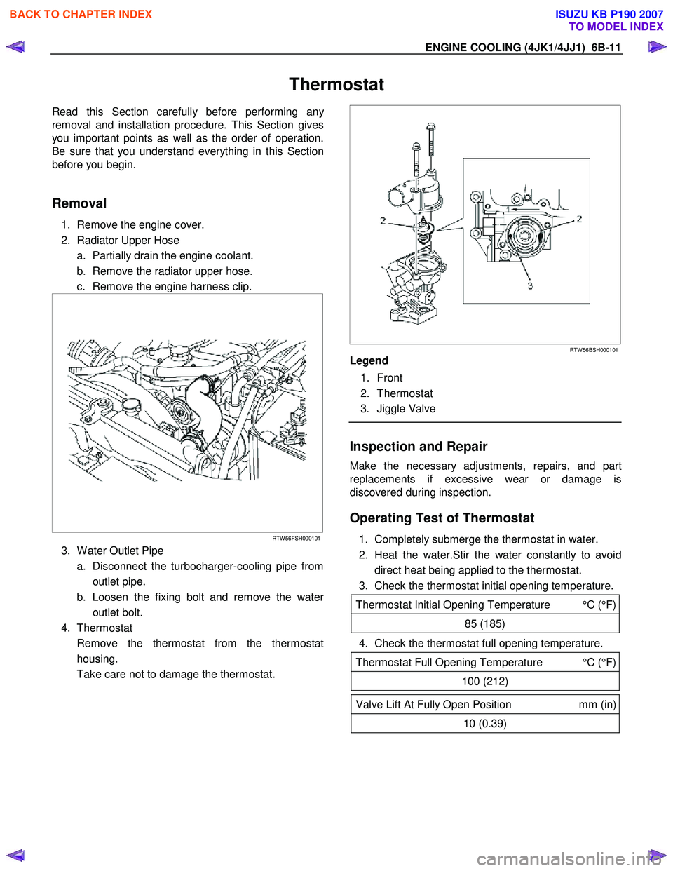
RTW 56FSH000101
3. W ater Outlet Pipe
a. Disconnect the turbocharger-cooling pipe from outlet pipe.
b. Loosen the fixing bolt and remove the wate
r
outlet bolt.
4. Thermostat
Remove the thermostat from the thermostat housing.
Take care not to damage the thermostat.
RTW 56BSH000101
Legend
1. Front
2. Thermostat
3. Jiggle Valve
Inspection and Repair
Make the necessary adjustments, repairs, and part
replacements if excessive wear or damage is
discovered during inspection.
Operating Test of Thermostat
1. Completely submerge the thermostat in water.
2. Heat the water.Stir the water constantly to avoid direct heat being applied to the thermostat.
3. Check the thermostat initial opening temperature.
Thermostat Initial Opening Temperature °C (°F)
85 (185)
4. Check the thermostat full opening temperature.
Thermostat Full Opening Temperature °C (°F)
100 (212)
Valve Lift At Fully Open Position mm (in)
10 (0.39)
BACK TO CHAPTER INDEX
TO MODEL INDEX
ISUZU KB P190 2007
Page 1535 of 6020
6B-12 ENGINE COOLING (4JK1/4JJ1)
MFW 41CSH001401
Legend
1. W ooden Piece
2. Agitating Rod
Installation
1. Thermostat
Install the thermostat.
Mount the jiggle valve with the valve facing engine front.
RTW 56BSH000101
Legend
1. Front
2. Thermostat
3. Jiggle Valve
2. W ater Outlet Pipe.
a. Install the water outlet pipe with new gasket to the thermostat housing.
b. Tighten the outlet pipe bolt to specified torque.
Outlet Pipe Bolt Torque: 25 N·m (2.5 kg·m /18 lb ft)
c. Connect the turbocharger-cooling pipe to outlet pipe.
d. Install the engine harness clip.
3. Radiator Upper Hose.
RTW 56FSH000101
a. Connect the radiator upper hose to the water
outlet pipe.
b. The knob of the clamp should be directed to the horizontal side.
c. Replenish the engine coolant.
4. Install the engine cover.
BACK TO CHAPTER INDEX
TO MODEL INDEX
ISUZU KB P190 2007
Page 1551 of 6020
6C-10 FUEL SYSTEM (4JK1/4JJ1)
Fuel System Check
Description
Conforms to a fuel leak. Engine acceleration raises fuel
pressure and which increases the leak.
Leak could be in the following pipes and locations.
• Between injectors and fuel rail.
• Between fuel rail and fuel supply pump.
• Between fuel supply pump and fuel filter.
• Between fuel filter and fuel tank.
• Between pressure limiter and fuel cooler.
• Between fuel cooler and fuel tank.
• Between injector over flow and leak off pipe.
Diagnostic Aids
Check the following items.
• Air in the fuel line
• Clogged fuel filter
• Fuel pipe malfunction (Crushing, breakage,
clogging, disconnection, etc.)
• Fuel cooler malfunction (Crushing, breakage,
clogging, disconnection, etc.)
• Fuel tank malfunction
• Injector malfunction
• Fuel supply pump malfunction
• Pressure limiter malfunction
An intermittent may be caused by a poor connection,
rubbed-through wire insulation or a wire broken inside
the insulation. Check for poor connections or a
damaged harness.
Inspect the ECM harness and connector for imprope
r
mating, broken locks, improperly formed or damaged
terminals, poor terminal-to-wire connection, and
damaged harness.
ECU may set a DTC, if there is adequate air in fuel line.
Schematic Reference: Engine Controls Schematics
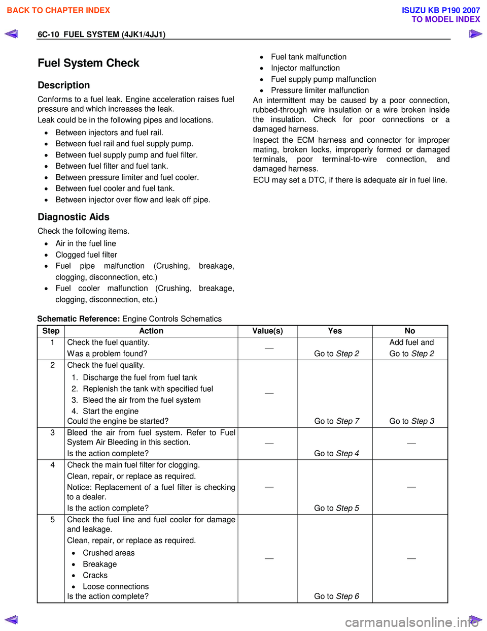
Step Action Value(s) Yes No
1 Check the fuel quantity. W as a problem found?
Go to Step 2 Add fuel and
Go to Step 2
2 Check the fuel quality.
1. Discharge the fuel from fuel tank
2. Replenish the tank with specified fuel
3. Bleed the air from the fuel system
4. Start the engine
Could the engine be started?
Go to Step 7 Go to Step 3
3 Bleed the air from fuel system. Refer to Fuel
System Air Bleeding in this section.
Is the action complete?
Go to Step 4
4 Check the main fuel filter for clogging.
Clean, repair, or replace as required.
Notice: Replacement of a fuel filter is checking
to a dealer.
Is the action complete?
Go to Step 5
5 Check the fuel line and fuel cooler for damage
and leakage.
Clean, repair, or replace as required.
• Crushed areas
• Breakage
• Cracks
• Loose connections
Is the action complete?
Go to Step 6
BACK TO CHAPTER INDEX
TO MODEL INDEX
ISUZU KB P190 2007
Page 1553 of 6020
6C-12 FUEL SYSTEM (4JK1/4JJ1)
Fuel Filter Assembly
Components
RTW 76CSF000101
Legend
1. Fuel Sedimenter Connector 2. Bolt
3. Harness Connector
4. Fuel Hose
5. Fuel Filter Assembly
Removal
1. Remove the fuel filler cap.
2. Remove the fuel sedimenter connector.
3. Disconnect the harness connector.
4. Remove the feed hose and the return hose from the fuel filter and plug it so that the fuel does not
flow out.
5. Remove the bolts for mounting the fuel filter.
6. Remove the fuel filter assembly.
Installation
1. Install the fuel filter assembly.
2. Install the bolts for mounting the fuel filter.
3. Install the feed hose and the return hose.
4. Connect the harness connector.
5. Install the fuel sedimenter connector.
6. Install the fuel filler cap.
7. Bleed out the air. • Refer to "Fuel System".
BACK TO CHAPTER INDEX
TO MODEL INDEX
ISUZU KB P190 2007
Page 1554 of 6020
FUEL SYSTEM (4JK1/4JJ1) 6C-13
Fuel Filter Element
Removal
1. Detach the drain hose on the lower part of the fuel
filter or the drain plug, loosen the air bleed plug,
and drain the fuel from the fuel filter.
2. Detach the water-in-fuel switch harness.
3. Turn the element case counterclockwise to detach, and remove the filter element.
4. Replace the O-ring and confirm the snap-fit position, and fit a new filter element inside the
element case.
NOTE
It is strongly advisable to use the ISUZU/GM genuine
fuel filter for replacement.
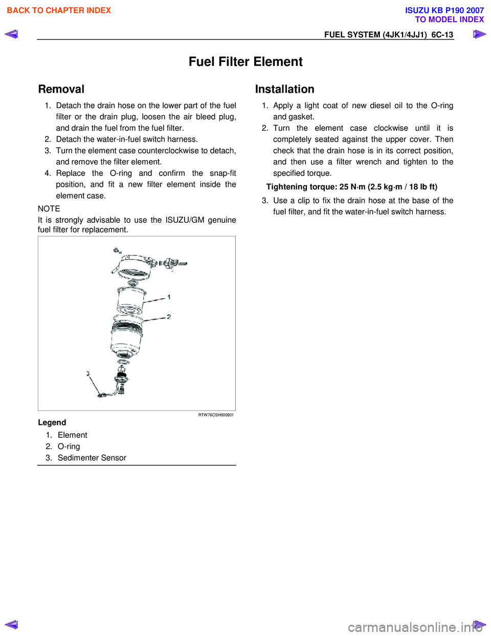
RTW 76CSH000901
Legend
1. Element
2. O-ring
3. Sedimenter Sensor
Installation
1. Apply a light coat of new diesel oil to the O-ring
and gasket.
2. Turn the element case clockwise until it is completely seated against the upper cover. Then
check that the drain hose is in its correct position,
and then use a filter wrench and tighten to the
specified torque.
Tightening torque: 25 N ⋅
⋅⋅
⋅
m (2.5 kg ⋅
⋅⋅
⋅
m / 18 lb ft)
3. Use a clip to fix the drain hose at the base of the fuel filter, and fit the water-in-fuel switch harness.
BACK TO CHAPTER INDEX
TO MODEL INDEX
ISUZU KB P190 2007
Page 1558 of 6020
FUEL SYSTEM (4JK1/4JJ1) 6C-17
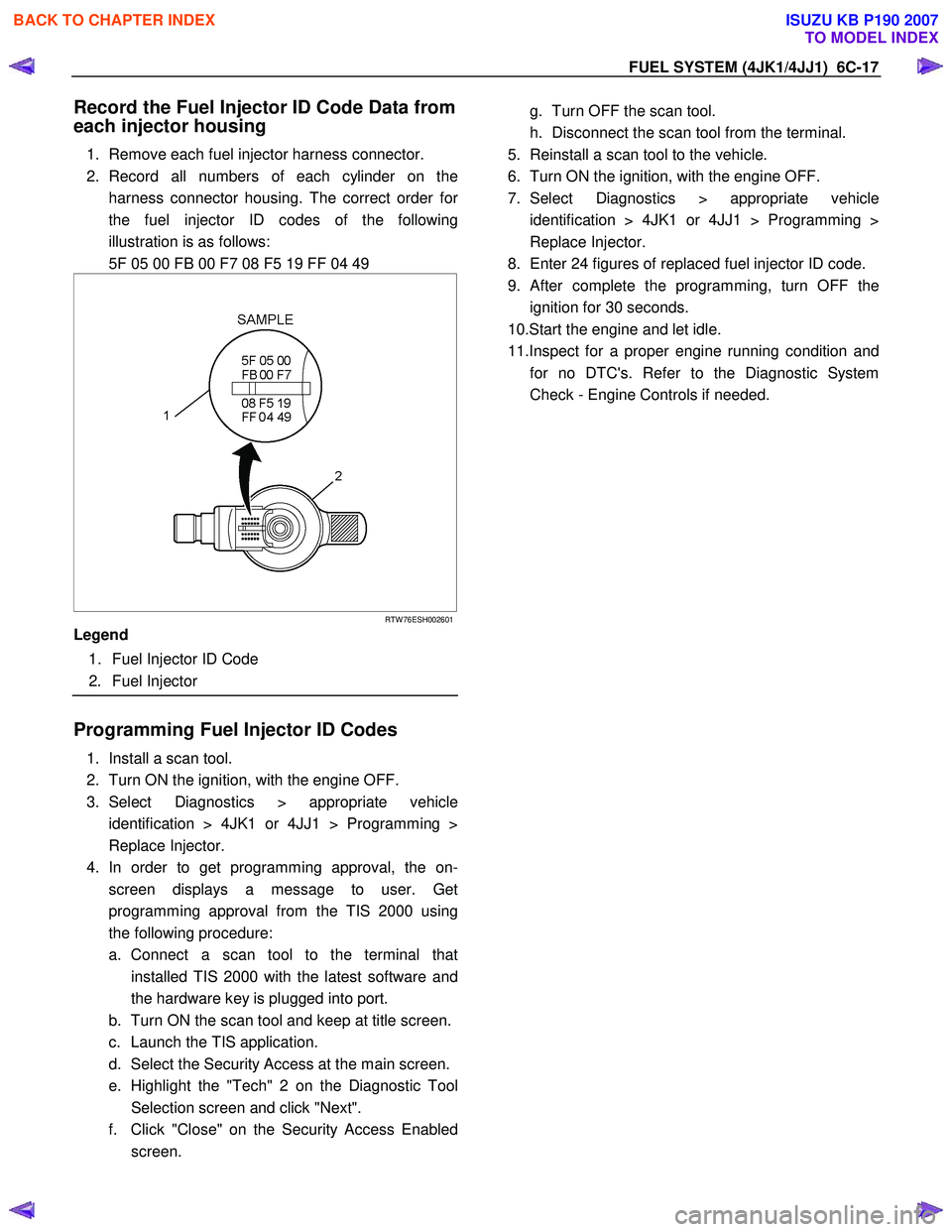
Record the Fuel Injector ID Code Data from
each injector housing
1. Remove each fuel injector harness connector.
2. Record all numbers of each cylinder on the harness connector housing. The correct order fo
r
the fuel injector ID codes of the following
illustration is as follows:
5F 05 00 FB 00 F7 08 F5 19 FF 04 49
RTW 76ESH002601
Legend
1. Fuel Injector ID Code
2. Fuel Injector
Programming Fuel Injector ID Codes
1. Install a scan tool.
2. Turn ON the ignition, with the engine OFF.
3. Select Diagnostics > appropriate vehicle identification > 4JK1 or 4JJ1 > Programming >
Replace Injector.
4. In order to get programming approval, the on- screen displays a message to user. Get
programming approval from the TIS 2000 using
the following procedure:
a. Connect a scan tool to the terminal that installed TIS 2000 with the latest software and
the hardware key is plugged into port.
b. Turn ON the scan tool and keep at title screen.
c. Launch the TIS application.
d. Select the Security Access at the main screen.
e. Highlight the "Tech" 2 on the Diagnostic Tool Selection screen and click "Next".
f. Click "Close" on the Security Access Enabled screen.
g. Turn OFF the scan tool.
h. Disconnect the scan tool from the terminal.
5. Reinstall a scan tool to the vehicle.
6. Turn ON the ignition, with the engine OFF.
7. Select Diagnostics > appropriate vehicle identification > 4JK1 or 4JJ1 > Programming >
Replace Injector.
8. Enter 24 figures of replaced fuel injector ID code.
9.
After complete the programming, turn OFF the
ignition for 30 seconds.
10.Start the engine and let idle.
11.Inspect for a proper engine running condition and for no DTC's. Refer to the Diagnostic System
Check - Engine Controls if needed.
BACK TO CHAPTER INDEX
TO MODEL INDEX
ISUZU KB P190 2007
Page 1560 of 6020
FUEL SYSTEM (4JK1/4JJ1) 6C-19
Fuel Rail Pressure Sensor
Removal
1. Disconnect the fuel pressure sensor harness
connector (1).
LNW 76CSH001601
2. Remove the fuel pressure sensor (2).
Note: Cover the areas exposed during parts removal to
prevent the entry of foreign material into the fuel
system.
RTW 76CSH000101
Legend
1. Fuel Rail
2. Fuel Rail Pressure Sensor
3. Fuel Pressure Limiter
Installation
1. Install the fuel pressure sensor.
Tightening torque: 98 N·m (10.0 kg·m/72 lb ft)
2. Connect the fuel pressure sensor connector.
BACK TO CHAPTER INDEX
TO MODEL INDEX
ISUZU KB P190 2007