2007 ISUZU KB P190 Harness
[x] Cancel search: HarnessPage 1365 of 6020
ENGINE MECHANICAL (4JK1/4JJ1) 6A-5
EGR system
Based upon data, including water temperature, engine
speeds or engine loads, it is controlled via Engine
Control Module (ECM) to purify exhaust by recycling
part of it.
Its main components include an EGR valve, an EGR
cooler and various sensors.
Connecting rod cap bolt
The angular tightening method of the connecting rod
cap bolt further increases reliability and durability.
Fuel rail-type electronic control injection system
The fuel rail-type electronic control injection system is
composed of a fuel supply pump that sets the target
pressure of high-pressure fuel and supply it, a fuel rail
that measures such high-pressure fuel and a fuel
injector that turns it into a fine spray and injects it. Each
is controlled via ECM based upon various signals, while
injection timing or fuel injection quantity is controlled
under every possible driving condition.
Fuel injector
The fuel injector is a 6-hole nozzle that adjusts fuel
injection quantity or injection timing by opening o
r
closing an electromagnetic valve on the head of the fuel
injector.
ECM corrects the dispersion of fuel injection quantit
y
between fuel injector according to ID code data in
memory. At the replacement of fuel injector, ID code
data should be stored in ECM.
Fuel filter with sedimenter
It is a fuel filter with sedimenter that gets rid of water by
making use of the difference in specific gravity between
light oil and water, which comes with an indicator that
notifies you that it is filled with water.
Preheating system
The preheating system consists of the ECM, the glow
relay, glow plugs and the glow indicator lamp. The
preheating system is operated when the engine coolant
temperature is low, and makes the engine easy to start.
Lubrication system
It is an oil filter with full-flow bypass, which uses a
water-cool oil cooler and oil jet to cool the piston.
Functional inspection
Inspection/adjustment of valve clearance 1. Inspection of valve clearance
• Remove the fuel injector harness assembly.
• Remove the leak off hose.
• Remove the cylinder head cover.
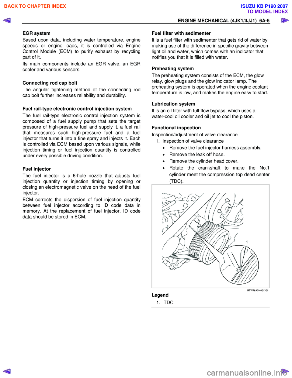
• Rotate the crankshaft to make the No.1
cylinder meet the compression top dead cente
r
(TDC).
RTW 76ASH001301
Legend
1. TDC
BACK TO CHAPTER INDEX
TO MODEL INDEX
ISUZU KB P190 2007
Page 1366 of 6020
6A-6 ENGINE MECHANICAL (4JK1/4JJ1)
• Insert a 0.15 mm (0.006 in) thickness gauge
between the roller of the rocker arm and the
camshaft to tighten up the adjusting screw o
f
the rocker arm. W hen the movement of the
thickness gauge becomes tight, fasten the
adjusting screw nut of the rocker arm.
Valve clearance mm (in)
Intake valve 0.15 (0.006)
Exhaust valve 0.15 (0.006)
Note:
Adjust while cold.
2. Adjustment of valve clearance • Loosen each adjusting screw of the rocker arm
completely.
RTW 56ASH003701
Legend
1. Screwdriver
2. Ring Spanner
3. Valve Clearance Adjust Nut W rench
Special tool
Valve clearance adjust nut wrench: 5-8840-2822-0
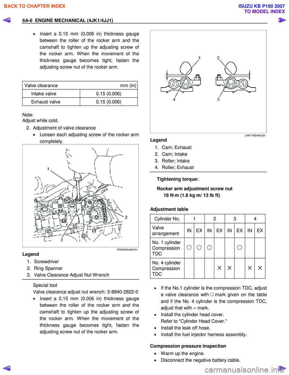
• Insert a 0.15 mm (0.006 in) thickness gauge
between the roller of the rocker arm and the
camshaft to tighten up the adjusting screw o
f
the rocker arm. W hen the movement of the
thickness gauge becomes tight, fasten the
adjusting screw nut of the rocker arm.
LHW 71BSH001201
Legend
1. Cam; Exhaust
2. Cam; Intake
3. Roller; Intake
4. Roller; Exhaust
Tightening torque:
Rocker arm adjustment screw nut 18 N ⋅
⋅⋅
⋅
m (1.8 kg ⋅
⋅⋅
⋅
m/ 13 lb ft)
Adjustment table
Cylinder No. 1 2 3 4
Valve
arrangement IN EX IN EX IN EX IN EX
No. 1 cylinder
Compression
TDC
No. 4 cylinder
Compression
TDC
× × × ×
• If the No.1 cylinder is the compression TDC, adjust
a valve clearance with
mark given on the table
and if the No. 4 cylinder is the compression TDC,
adjust that with × mark.
• Install the cylinder head cover.
Refer to "Cylinder Head Cover."
• Install the leak off hose.
• Install the fuel injector harness assembly.
Compression pressure inspection
• W arm up the engine.
• Disconnect the negative battery cable.
BACK TO CHAPTER INDEX
TO MODEL INDEX
ISUZU KB P190 2007
Page 1367 of 6020
ENGINE MECHANICAL (4JK1/4JJ1) 6A-7
• Remove the all glow plugs.
Note:
W hen the harness connector is removed, ECM judges
that it broke down and DTC is recorded. Upon
completion of measurement, never fail to clear the
memory of the ECM.
(For how to clear the memory of the ECM, refer to
“ENGINE CONTROL SYSTEM” Section)
• Connect the negative battery cable.
• Turn on the starter to emit foreign matter within the
cylinders.
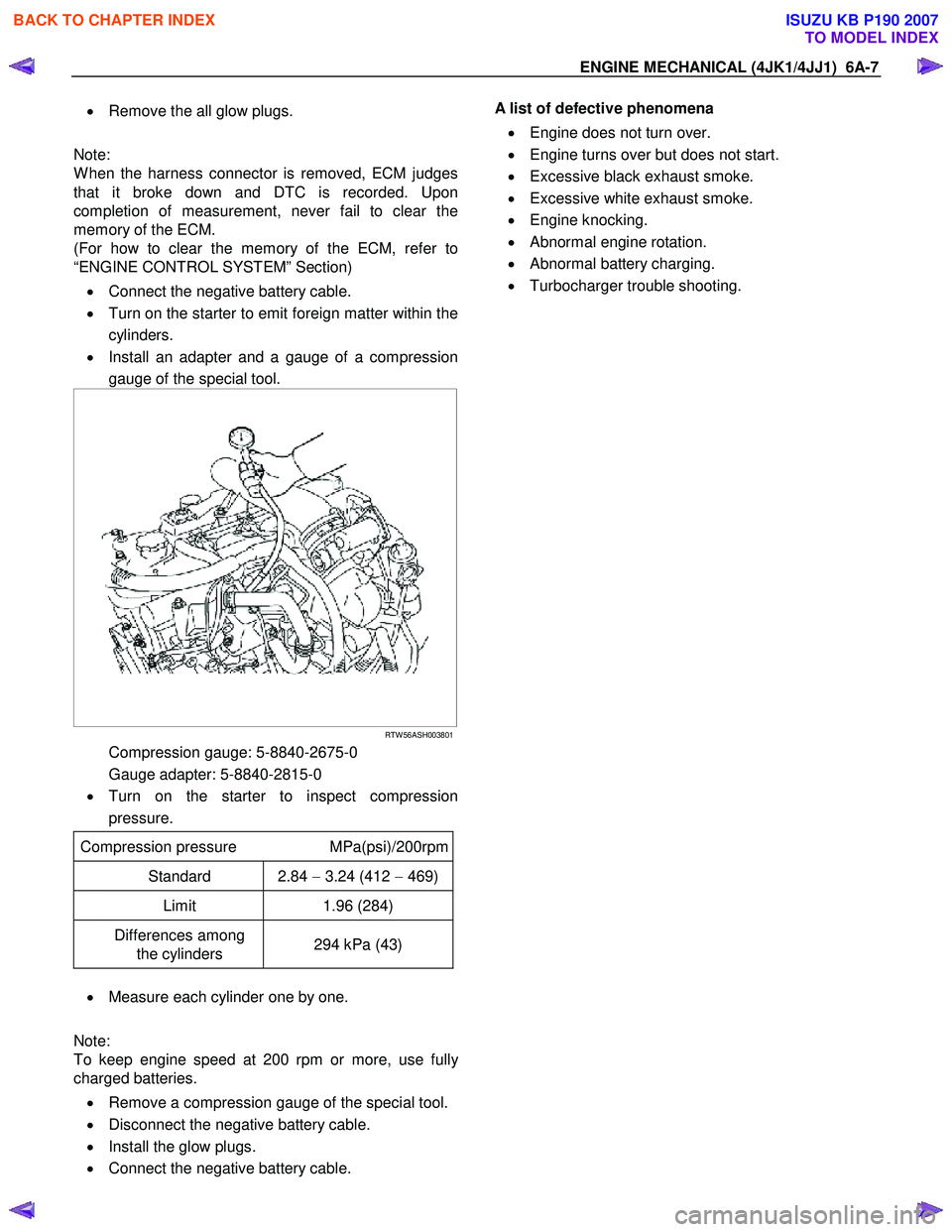
• Install an adapter and a gauge of a compression
gauge of the special tool.
RTW 56ASH003801
Compression gauge: 5-8840-2675-0
Gauge adapter: 5-8840-2815-0
• Turn on the starter to inspect compression
pressure.
Compression pressure MPa(psi)/200rpm
Standard 2.84 − 3.24 (412 − 469)
Limit 1.96 (284)
Differences among
the cylinders 294 kPa (43)
•
Measure each cylinder one by one.
Note:
To keep engine speed at 200 rpm or more, use full
y
charged batteries.
• Remove a compression gauge of the special tool.
• Disconnect the negative battery cable.
• Install the glow plugs.
• Connect the negative battery cable.
A list of defective phenomena
• Engine does not turn over.
• Engine turns over but does not start.
• Excessive black exhaust smoke.
• Excessive white exhaust smoke.
• Engine knocking.
• Abnormal engine rotation.
• Abnormal battery charging.
• Turbocharger trouble shooting.
BACK TO CHAPTER INDEX
TO MODEL INDEX
ISUZU KB P190 2007
Page 1375 of 6020
ENGINE MECHANICAL (4JK1/4JJ1) 6A-15
Engine Assembly
Removal
1. Disconnect the negative battery cable.
2. Remove the engine hood.
3. Drain the coolant.
4. Remove the starter motor.
5. Remove the transmission assembly.
Refer to removal procedure for “TRANSMISSION” in this manual.
6. Disconnect the ECM harness connector.
7. Remove the ECM.
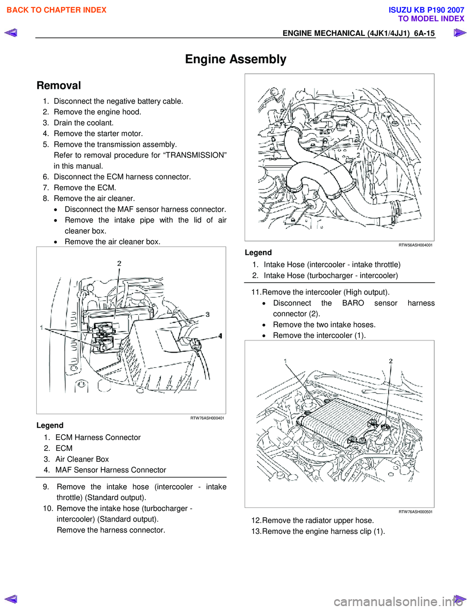
8. Remove the air cleaner. • Disconnect the MAF sensor harness connector.
• Remove the intake pipe with the lid of ai
r
cleaner box.
• Remove the air cleaner box.
RTW 76ASH000401
Legend
1. ECM Harness Connector
2. ECM
3. Air Cleaner Box
4. MAF Sensor Harness Connector
9. Remove the intake hose (intercooler - intake
throttle) (Standard output).
10. Remove the intake hose (turbocharger - intercooler) (Standard output).
Remove the harness connector.
RTW 56ASH004001
Legend
1. Intake Hose (intercooler - intake throttle)
2. Intake Hose (turbocharger - intercooler)
11. Remove the intercooler (High output).
• Disconnect the BARO sensor harness
connector (2).
• Remove the two intake hoses.
• Remove the intercooler (1).
RTW 76ASH000501
12. Remove the radiator upper hose.
13. Remove the engine harness clip (1).
BACK TO CHAPTER INDEX
TO MODEL INDEX
ISUZU KB P190 2007
Page 1376 of 6020
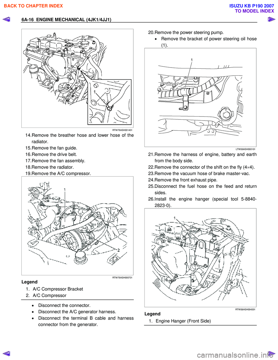
6A-16 ENGINE MECHANICAL (4JK1/4JJ1)
RTW 76ASH001401
14. Remove the breather hose and lower hose of the
radiator.
15. Remove the fan guide.
16. Remove the drive belt.
17. Remove the fan assembly.
18.Remove the radiator.
19.Remove the A/C compressor.
RTW 76ASH000701
Legend
1. A/C Compressor Bracket
2. A/C Compressor
• Disconnect the connector.
• Disconnect the A/C generator harness.
• Disconnect the terminal B cable and harness
connector from the generator.
20.Remove the power steering pump.
• Remove the bracket of power steering oil hose
(1).
LTW 56ASH000101
21.Remove the harness of engine, battery and earth
from the body side.
22.Remove the connector of the shift on the fly (4 ×4).
23.Remove the vacuum hose of brake master-vac.
24.Remove the front exhaust pipe.
25.Disconnect the fuel hose on the feed and return sides.
26.Install the engine hanger (special tool 5-8840- 2823-0).
RTW 56ASH004301
Legend
1. Engine Hanger (Front Side)
BACK TO CHAPTER INDEX
TO MODEL INDEX
ISUZU KB P190 2007
Page 1377 of 6020
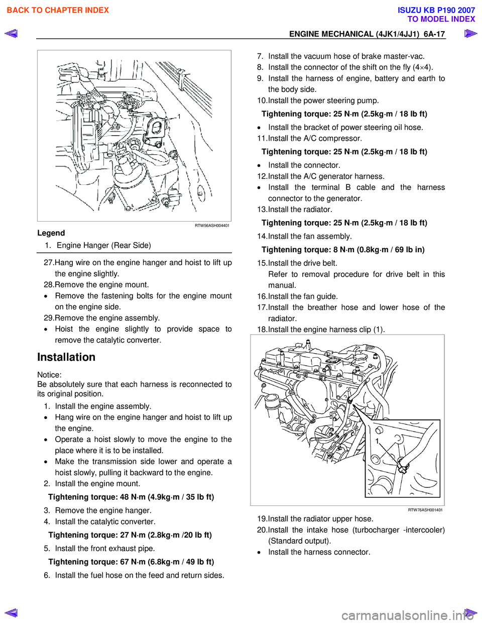
ENGINE MECHANICAL (4JK1/4JJ1) 6A-17
RTW 56ASH004401
Legend
1. Engine Hanger (Rear Side)
27.Hang wire on the engine hanger and hoist to lift up
the engine slightly.
28.Remove the engine mount.
• Remove the fastening bolts for the engine mount
on the engine side.
29.Remove the engine assembly.
• Hoist the engine slightly to provide space to
remove the catalytic converter.
Installation
Notice:
Be absolutely sure that each harness is reconnected to
its original position.
1. Install the engine assembly.
• Hang wire on the engine hanger and hoist to lift up
the engine.
• Operate a hoist slowly to move the engine to the
place where it is to be installed.
• Make the transmission side lower and operate a
hoist slowly, pulling it backward to the engine.
2. Install the engine mount.
Tightening torque: 48 N ⋅
⋅⋅
⋅
m (4.9kg ⋅
⋅⋅
⋅
m / 35 lb ft)
3. Remove the engine hanger.
4. Install the catalytic converter.
Tightening torque: 27 N ⋅
⋅⋅
⋅
m (2.8kg ⋅
⋅⋅
⋅
m /20 lb ft)
5. Install the front exhaust pipe. Tightening torque: 67 N ⋅
⋅⋅
⋅
m (6.8kg ⋅
⋅⋅
⋅
m / 49 lb ft)
6. Install the fuel hose on the feed and return sides.
7. Install the vacuum hose of brake master-vac.
8. Install the connector of the shift on the fly (4 ×4).
9. Install the harness of engine, battery and earth to the body side.
10.Install the power steering pump.
Tightening torque: 25 N ⋅
⋅⋅
⋅
m (2.5kg ⋅
⋅⋅
⋅
m / 18 lb ft)
• Install the bracket of power steering oil hose.
11.Install the A/C compressor.
Tightening torque: 25 N ⋅
⋅⋅
⋅
m (2.5kg ⋅
⋅⋅
⋅
m / 18 lb ft)
• Install the connector.
12.Install the A/C generator harness.
• Install the terminal B cable and the harness
connector to the generator.
13.Install the radiator.
Tightening torque: 25 N ⋅
⋅⋅
⋅
m (2.5kg ⋅
⋅⋅
⋅
m / 18 lb ft)
14.Install the fan assembly. Tightening torque: 8 N ⋅
⋅⋅
⋅
m (0.8kg ⋅
⋅⋅
⋅
m / 69 lb in)
15.Install the drive belt.
Refer to removal procedure for drive belt in this manual.
16.Install the fan guide.
17.Install the breather hose and lower hose of the radiator.
18.Install the engine harness clip (1).
RTW 76ASH001401
19.Install the radiator upper hose.
20.Install the intake hose (turbocharger -intercooler) (Standard output).
• Install the harness connector.
BACK TO CHAPTER INDEX
TO MODEL INDEX
ISUZU KB P190 2007
Page 1378 of 6020
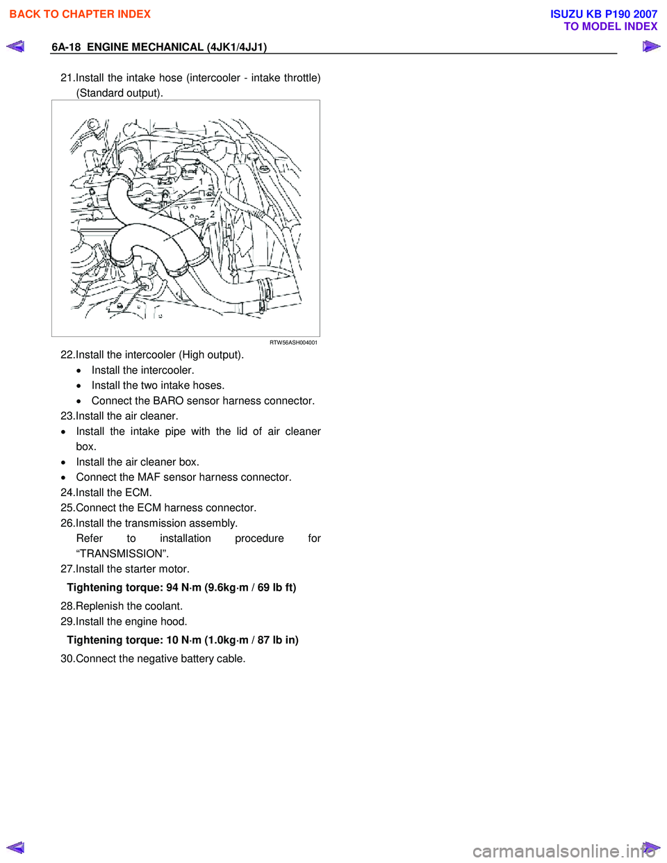
6A-18 ENGINE MECHANICAL (4JK1/4JJ1)
21.Install the intake hose (intercooler - intake throttle)
(Standard output).
RTW 56ASH004001
22.Install the intercooler (High output).
• Install the intercooler.
• Install the two intake hoses.
• Connect the BARO sensor harness connector.
23.Install the air cleaner.
• Install the intake pipe with the lid of air cleane
r
box.
• Install the air cleaner box.
• Connect the MAF sensor harness connector.
24.Install the ECM.
25.Connect the ECM harness connector.
26.Install the transmission assembly.
Refer to installation procedure fo
r
“TRANSMISSION”.
27.Install the starter motor.
Tightening torque: 94 N ⋅
⋅⋅
⋅
m (9.6kg ⋅
⋅⋅
⋅
m / 69 lb ft)
28.Replenish the coolant.
29.Install the engine hood.
Tightening torque: 10 N ⋅
⋅⋅
⋅
m (1.0kg ⋅
⋅⋅
⋅
m / 87 lb in)
30.Connect the negative battery cable.
BACK TO CHAPTER INDEX
TO MODEL INDEX
ISUZU KB P190 2007
Page 1384 of 6020
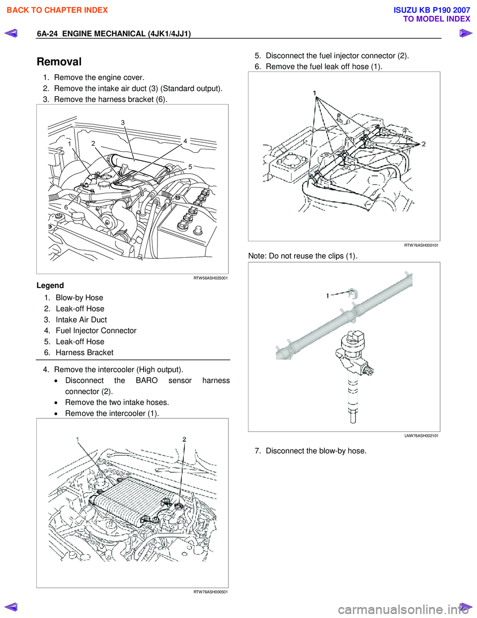
6A-24 ENGINE MECHANICAL (4JK1/4JJ1)
Removal
1. Remove the engine cover.
2. Remove the intake air duct (3) (Standard output).
3. Remove the harness bracket (6).
RTW 56ASH025001
Legend
1. Blow-by Hose
2. Leak-off Hose
3. Intake Air Duct
4. Fuel Injector Connector
5. Leak-off Hose
6. Harness Bracket
4. Remove the intercooler (High output).
• Disconnect the BARO sensor harness
connector (2).
• Remove the two intake hoses.
• Remove the intercooler (1).
RTW 76ASH000501
5. Disconnect the fuel injector connector (2).
6. Remove the fuel leak off hose (1).
RTW 76ASH000101
Note: Do not reuse the clips (1).
LNW 76ASH002101
7. Disconnect the blow-by hose.
BACK TO CHAPTER INDEX
TO MODEL INDEX
ISUZU KB P190 2007