2007 ISUZU KB P190 Harness
[x] Cancel search: HarnessPage 1676 of 6020
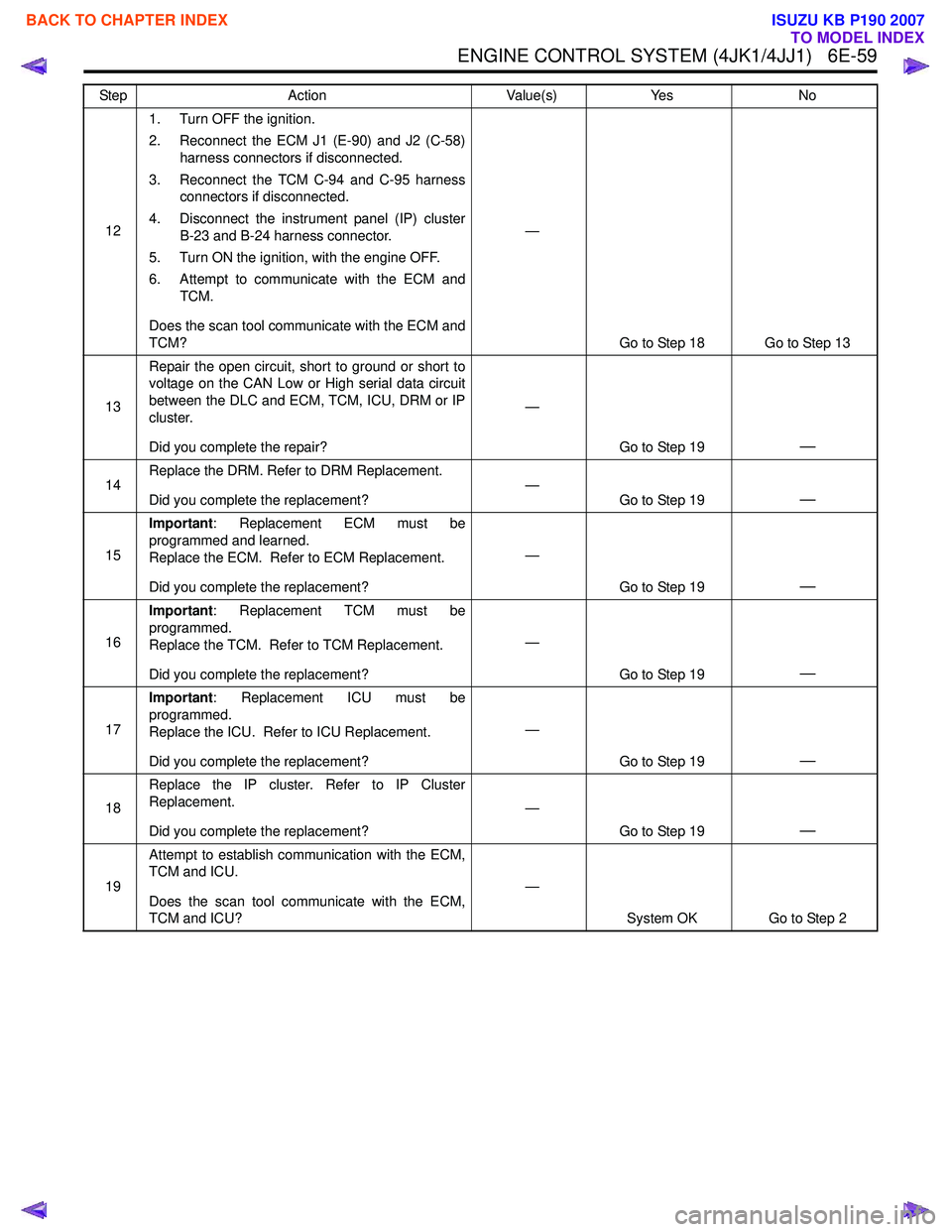
ENGINE CONTROL SYSTEM (4JK1/4JJ1) 6E-59
121. Turn OFF the ignition.
2. Reconnect the ECM J1 (E-90) and J2 (C-58) harness connectors if disconnected.
3. Reconnect the TCM C-94 and C-95 harness connectors if disconnected.
4. Disconnect the instrument panel (IP) cluster B-23 and B-24 harness connector.
5. Turn ON the ignition, with the engine OFF.
6. Attempt to communicate with the ECM and TCM.
Does the scan tool communicate with the ECM and
TCM? —
Go to Step 18 Go to Step 13
13 Repair the open circuit, short to ground or short to
voltage on the CAN Low or High serial data circuit
between the DLC and ECM, TCM, ICU, DRM or IP
cluster.
Did you complete the repair? —
Go to Step 19
—
14Replace the DRM. Refer to DRM Replacement.
Did you complete the replacement? —
Go to Step 19—
15Important
: Replacement ECM must be
programmed and learned.
Replace the ECM. Refer to ECM Replacement.
Did you complete the replacement? —
Go to Step 19
—
16Important
: Replacement TCM must be
programmed.
Replace the TCM. Refer to TCM Replacement.
Did you complete the replacement? —
Go to Step 19
—
17Important
: Replacement ICU must be
programmed.
Replace the ICU. Refer to ICU Replacement.
Did you complete the replacement? —
Go to Step 19
—
18Replace the IP cluster. Refer to IP Cluster
Replacement.
Did you complete the replacement? —
Go to Step 19
—
19Attempt to establish communication with the ECM,
TCM and ICU.
Does the scan tool communicate with the ECM,
TCM and ICU? —
System OK Go to Step 2
Step
Action Value(s)Yes No
BACK TO CHAPTER INDEX
TO MODEL INDEX
ISUZU KB P190 2007
Page 1677 of 6020
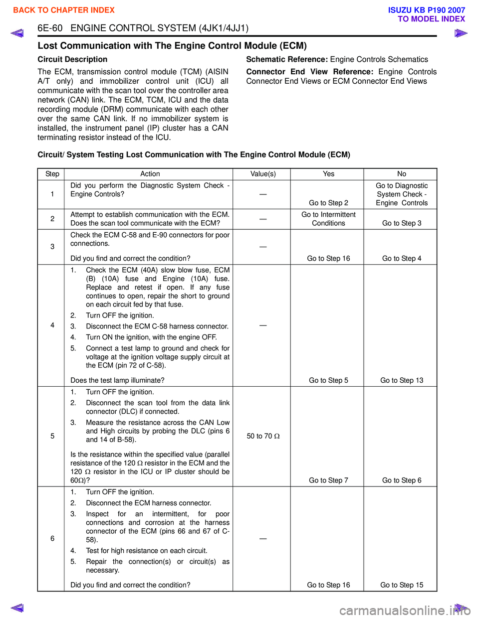
6E-60 ENGINE CONTROL SYSTEM (4JK1/4JJ1)
Lost Communication with The Engine Control Module (ECM)
Circuit Description
The ECM, transmission control module (TCM) (AISIN
A/T only) and immobilizer control unit (ICU) all
communicate with the scan tool over the controller area
network (CAN) link. The ECM, TCM, ICU and the data
recording module (DRM) communicate with each other
over the same CAN link. If no immobilizer system is
installed, the instrument panel (IP) cluster has a CAN
terminating resistor instead of the ICU. Schematic Reference:
Engine Controls Schematics
Connector End View Reference: Engine Controls
Connector End Views or ECM Connector End Views
Circuit/ System Testing Lost Communication with The Engine Control Module (ECM)
Step Action Value(s)Yes No
1 Did you perform the Diagnostic System Check -
Engine Controls? —
Go to Step 2 Go to Diagnostic
System Check -
Engine Controls
2 Attempt to establish communication with the ECM.
Does the scan tool communicate with the ECM? —Go to Intermittent
Conditions Go to Step 3
3 Check the ECM C-58 and E-90 connectors for poor
connections.
Did you find and correct the condition? —
Go to Step 16 Go to Step 4
4 1. Check the ECM (40A) slow blow fuse, ECM
(B) (10A) fuse and Engine (10A) fuse.
Replace and retest if open. If any fuse
continues to open, repair the short to ground
on each circuit fed by that fuse.
2. Turn OFF the ignition.
3. Disconnect the ECM C-58 harness connector.
4. Turn ON the ignition, with the engine OFF.
5. Connect a test lamp to ground and check for voltage at the ignition voltage supply circuit at
the ECM (pin 72 of C-58).
Does the test lamp illuminate? —
Go to Step 5 Go to Step 13
5 1. Turn OFF the ignition.
2. Disconnect the scan tool from the data link connector (DLC) if connected.
3. Measure the resistance across the CAN Low and High circuits by probing the DLC (pins 6
and 14 of B-58).
Is the resistance within the specified value (parallel
resistance of the 120 Ω resistor in the ECM and the
120 Ω resistor in the ICU or IP cluster should be
60 Ω)? 50 to 70
Ω
Go to Step 7 Go to Step 6
6 1. Turn OFF the ignition.
2. Disconnect the ECM harness connector.
3. Inspect for an intermittent, for poor connections and corrosion at the harness
connector of the ECM (pins 66 and 67 of C-
58).
4. Test for high resistance on each circuit.
5. Repair the connection(s) or circuit(s) as necessary.
Did you find and correct the condition? —
Go to Step 16 Go to Step 15
BACK TO CHAPTER INDEX
TO MODEL INDEX
ISUZU KB P190 2007
Page 1678 of 6020
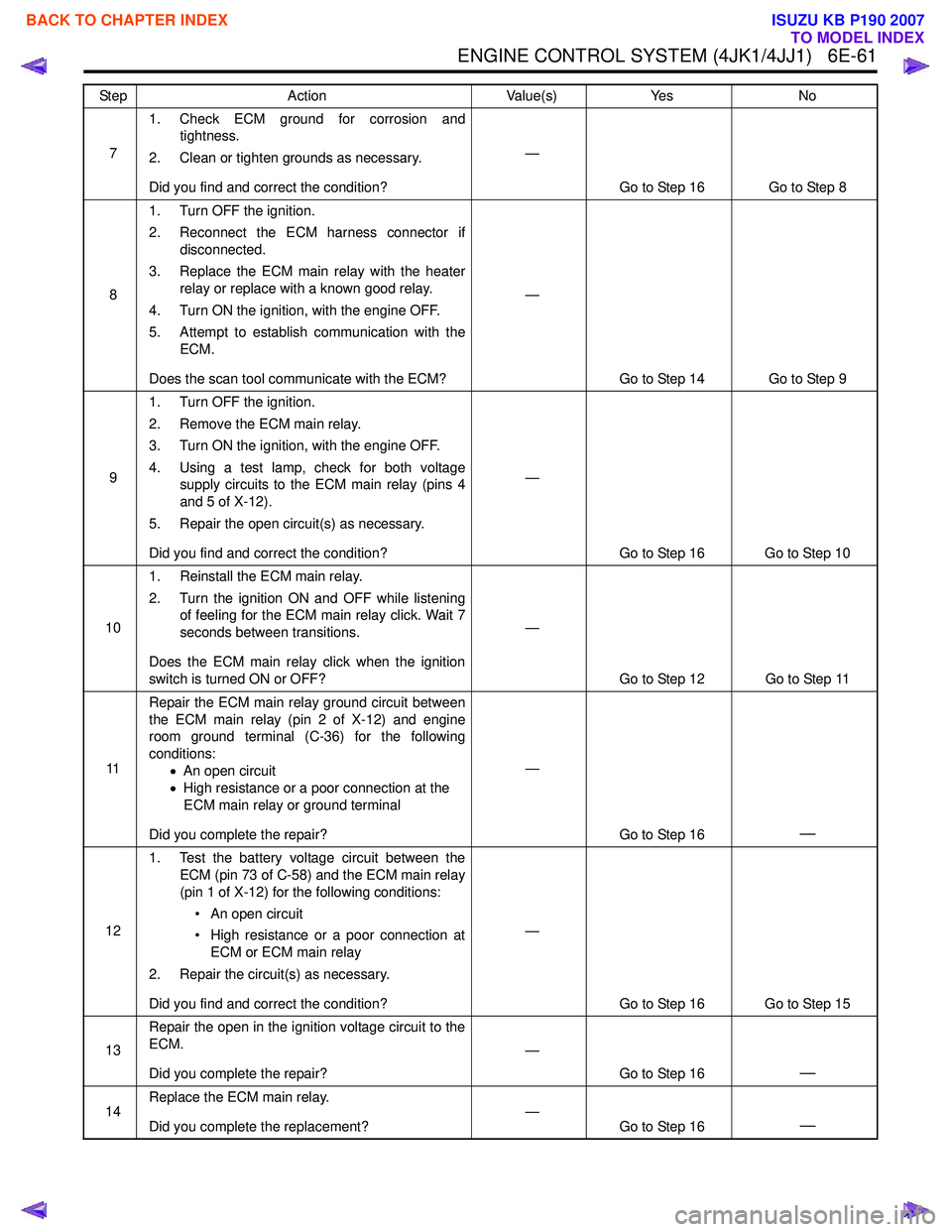
ENGINE CONTROL SYSTEM (4JK1/4JJ1) 6E-61
71. Check ECM ground for corrosion and
tightness.
2. Clean or tighten grounds as necessary.
Did you find and correct the condition? —
Go to Step 16 Go to Step 8
8 1. Turn OFF the ignition.
2. Reconnect the ECM harness connector if disconnected.
3. Replace the ECM main relay with the heater relay or replace with a known good relay.
4. Turn ON the ignition, with the engine OFF.
5. Attempt to establish communication with the ECM.
Does the scan tool communicate with the ECM? —
Go to Step 14 Go to Step 9
9 1. Turn OFF the ignition.
2. Remove the ECM main relay.
3. Turn ON the ignition, with the engine OFF.
4. Using a test lamp, check for both voltage supply circuits to the ECM main relay (pins 4
and 5 of X-12).
5. Repair the open circuit(s) as necessary.
Did you find and correct the condition? —
Go to Step 16 Go to Step 10
10 1. Reinstall the ECM main relay.
2. Turn the ignition ON and OFF while listening of feeling for the ECM main relay click. Wait 7
seconds between transitions.
Does the ECM main relay click when the ignition
switch is turned ON or OFF? —
Go to Step 12 Go to Step 11
11 Repair the ECM main relay ground circuit between
the ECM main relay (pin 2 of X-12) and engine
room ground terminal (C-36) for the following
conditions: •An open circuit
• High resistance or a poor connection at the
ECM main relay or ground terminal
Did you complete the repair? —
Go to Step 16
—
121. Test the battery voltage circuit between the
ECM (pin 73 of C-58) and the ECM main relay
(pin 1 of X-12) for the following conditions:
• An open circuit
• High resistance or a poor connection at ECM or ECM main relay
2. Repair the circuit(s) as necessary.
Did you find and correct the condition? —
Go to Step 16 Go to Step 15
13 Repair the open in the ignition voltage circuit to the
ECM.
Did you complete the repair? —
Go to Step 16
—
14Replace the ECM main relay.
Did you complete the replacement? —
Go to Step 16—
Step Action Value(s)Yes No
BACK TO CHAPTER INDEX
TO MODEL INDEX
ISUZU KB P190 2007
Page 1679 of 6020
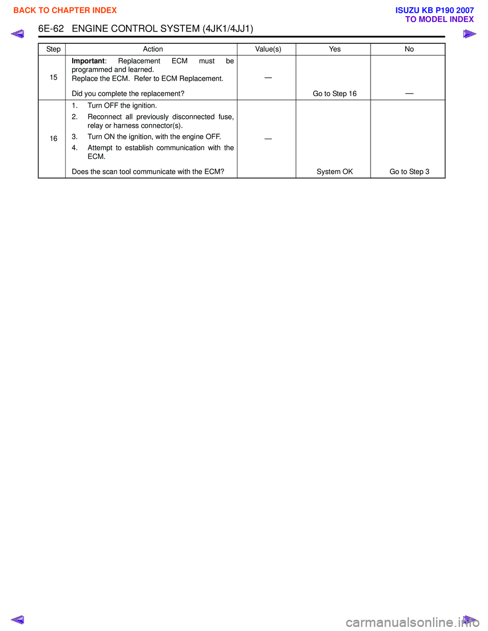
6E-62 ENGINE CONTROL SYSTEM (4JK1/4JJ1)
15Important
: Replacement ECM must be
programmed and learned.
Replace the ECM. Refer to ECM Replacement.
Did you complete the replacement? —
Go to Step 16
—
161. Turn OFF the ignition.
2. Reconnect all previously disconnected fuse, relay or harness connector(s).
3. Turn ON the ignition, with the engine OFF.
4. Attempt to establish communication with the ECM.
Does the scan tool communicate with the ECM? —
System OK Go to Step 3
Step
Action Value(s)Yes No
BACK TO CHAPTER INDEX
TO MODEL INDEX
ISUZU KB P190 2007
Page 1681 of 6020
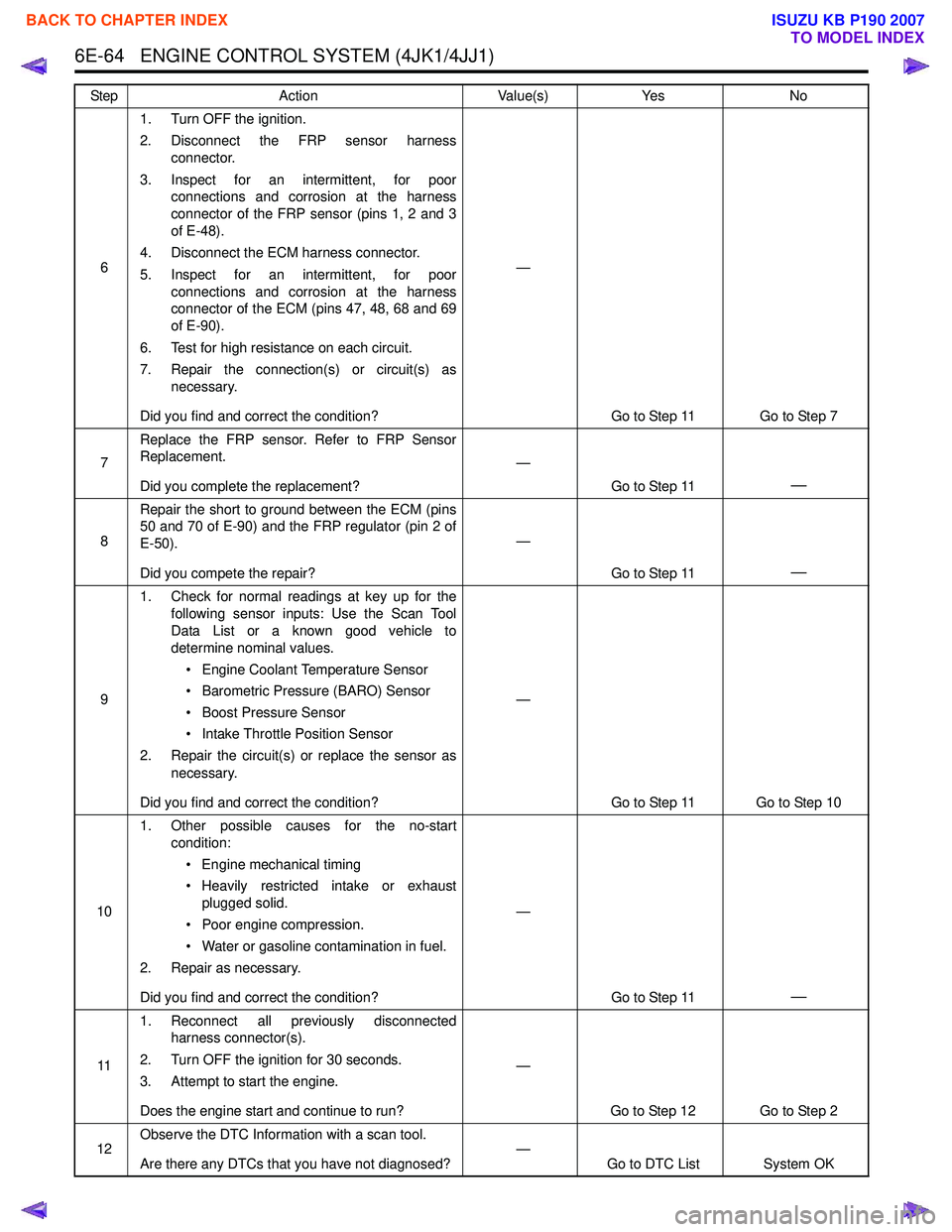
6E-64 ENGINE CONTROL SYSTEM (4JK1/4JJ1)
61. Turn OFF the ignition.
2. Disconnect the FRP sensor harness connector.
3. Inspect for an intermittent, for poor connections and corrosion at the harness
connector of the FRP sensor (pins 1, 2 and 3
of E-48).
4. Disconnect the ECM harness connector.
5. Inspect for an intermittent, for poor connections and corrosion at the harness
connector of the ECM (pins 47, 48, 68 and 69
of E-90).
6. Test for high resistance on each circuit.
7. Repair the connection(s) or circuit(s) as necessary.
Did you find and correct the condition? —
Go to Step 11 Go to Step 7
7 Replace the FRP sensor. Refer to FRP Sensor
Replacement.
Did you complete the replacement? —
Go to Step 11
—
8Repair the short to ground between the ECM (pins
50 and 70 of E-90) and the FRP regulator (pin 2 of
E-50).
Did you compete the repair? —
Go to Step 11
—
91. Check for normal readings at key up for the
following sensor inputs: Use the Scan Tool
Data List or a known good vehicle to
determine nominal values.
• Engine Coolant Temperature Sensor
• Barometric Pressure (BARO) Sensor
• Boost Pressure Sensor
• Intake Throttle Position Sensor
2. Repair the circuit(s) or replace the sensor as necessary.
Did you find and correct the condition? —
Go to Step 11 Go to Step 10
10 1. Other possible causes for the no-start
condition:
• Engine mechanical timing
• Heavily restricted intake or exhaust plugged solid.
• Poor engine compression.
• Water or gasoline contamination in fuel.
2. Repair as necessary.
Did you find and correct the condition? —
Go to Step 11
—
111. Reconnect all previously disconnected
harness connector(s).
2. Turn OFF the ignition for 30 seconds.
3. Attempt to start the engine.
Does the engine start and continue to run? —
Go to Step 12 Go to Step 2
12 Observe the DTC Information with a scan tool.
Are there any DTCs that you have not diagnosed? —
Go to DTC List System OK
Step
Action Value(s)Yes No
BACK TO CHAPTER INDEX
TO MODEL INDEX
ISUZU KB P190 2007
Page 1683 of 6020
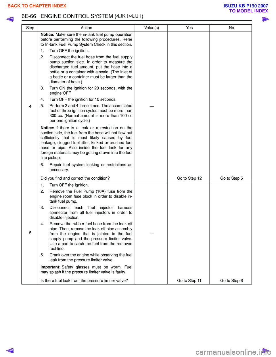
6E-66 ENGINE CONTROL SYSTEM (4JK1/4JJ1)
4Notice:
Make sure the in-tank fuel pump operation
before performing the following procedures. Refer
to In-tank Fuel Pump System Check in this section.
1. Turn OFF the ignition.
2. Disconnect the fuel hose from the fuel supply pump suction side. In order to measure the
discharged fuel amount, put the hose into a
bottle or a container with a scale. (The inlet of
a bottle or a container must be larger than the
diameter of hose.)
3. Turn ON the ignition for 20 seconds, with the engine OFF.
4. Turn OFF the ignition for 10 seconds.
5. Perform 3 and 4 three times. The accumulated fuel of three ignition cycles must be more than
300 cc. (Normal amount is more than 100 cc
per one ignition cycle.)
Notice: If there is a leak or a restriction on the
suction side, the fuel from the hose will not flow out
sufficiently that is most likely caused by fuel
leakage, clogged fuel filter, kinked or crushed fuel
hose or pipe. Also inside the fuel tank for any
foreign materials may be getting drawn into the fuel
line pickup.
6. Repair fuel system leaking or restrictions as necessary.
Did you find and correct the condition? —
Go to Step 12 Go to Step 5
5 1. Turn OFF the ignition.
2. Remove the Fuel Pump (10A) fuse from the engine room fuse block in order to disable in-
tank fuel pump.
3. Disconnect each fuel injector harness connector from all fuel injectors in order to
disable injection.
4. Remove the rubber fuel hose from the leak-off pipe. Then, remove the leak-off pipe assembly
from the engine that is jointed to the fuel
supply pump and the pressure limiter valve.
Use a pan to catch the fuel from the removed
fuel line.
5. Crank over the engine while observing the fuel leak from the pressure limiter valve.
Important: Safety glasses must be worm. Fuel
may splash if the pressure limiter valve is faulty.
Is there fuel leak from the pressure limiter valve? —
Go to Step 11 Go to Step 6
Step
Action Value(s)Yes No
BACK TO CHAPTER INDEX
TO MODEL INDEX
ISUZU KB P190 2007
Page 1685 of 6020
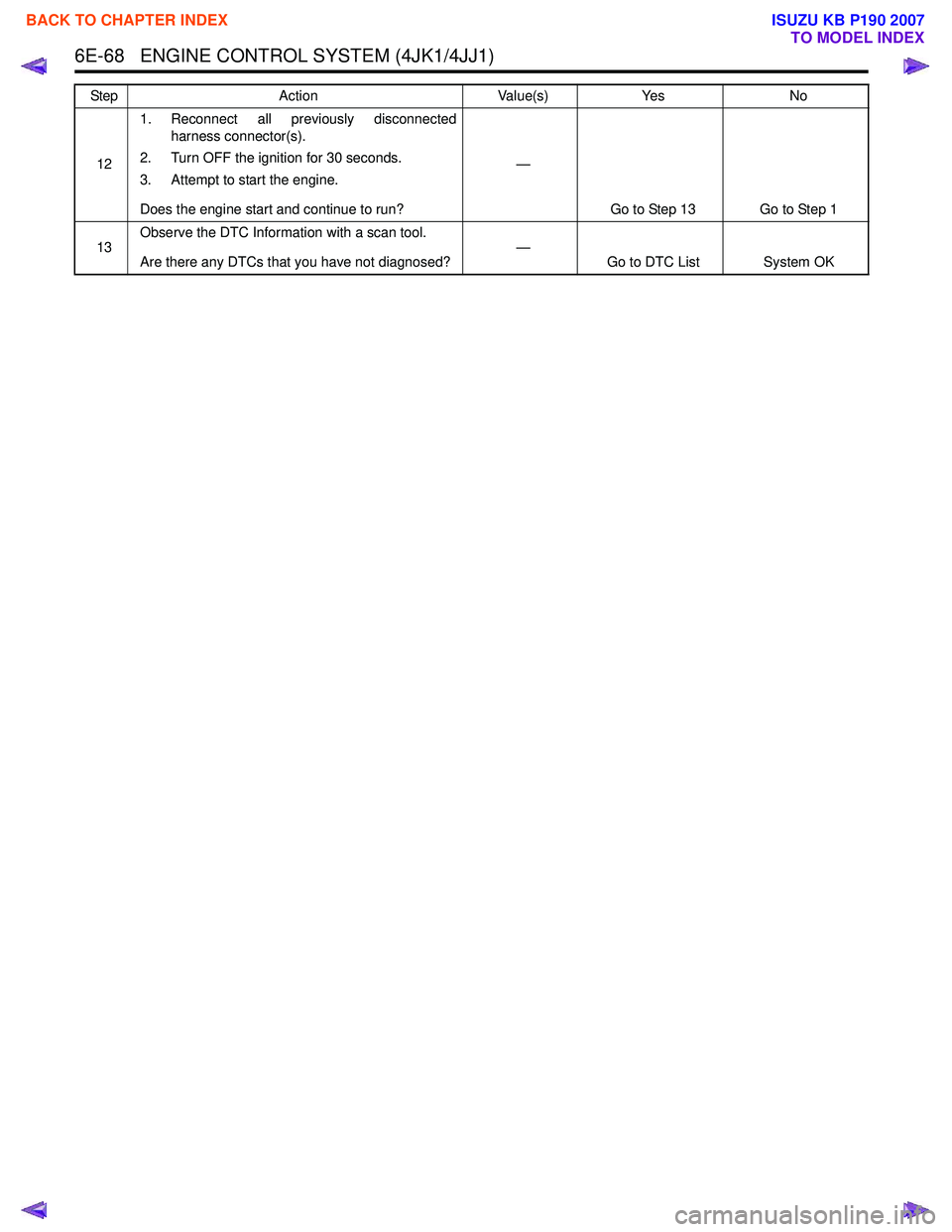
6E-68 ENGINE CONTROL SYSTEM (4JK1/4JJ1)
121. Reconnect all previously disconnected
harness connector(s).
2. Turn OFF the ignition for 30 seconds.
3. Attempt to start the engine.
Does the engine start and continue to run? —
Go to Step 13 Go to Step 1
13 Observe the DTC Information with a scan tool.
Are there any DTCs that you have not diagnosed? —
Go to DTC List System OK
Step
Action Value(s)Yes No
BACK TO CHAPTER INDEX
TO MODEL INDEX
ISUZU KB P190 2007
Page 1687 of 6020
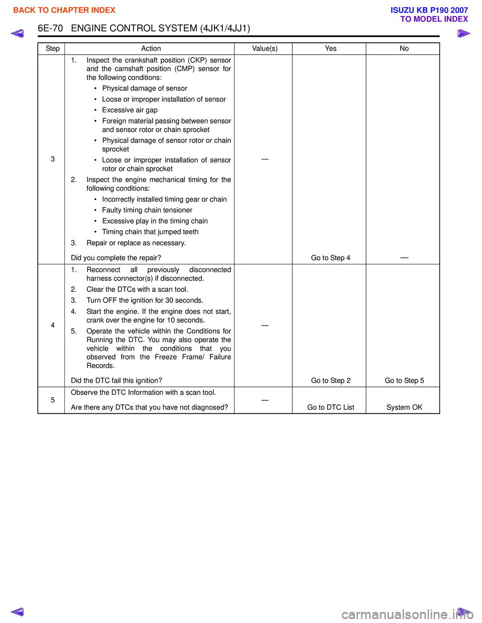
6E-70 ENGINE CONTROL SYSTEM (4JK1/4JJ1)
31. Inspect the crankshaft position (CKP) sensor
and the camshaft position (CMP) sensor for
the following conditions:
• Physical damage of sensor
• Loose or improper installation of sensor
• Excessive air gap
• Foreign material passing between sensor and sensor rotor or chain sprocket
• Physical damage of sensor rotor or chain sprocket
• Loose or improper installation of sensor rotor or chain sprocket
2. Inspect the engine mechanical timing for the following conditions:
• Incorrectly installed timing gear or chain
• Faulty timing chain tensioner
• Excessive play in the timing chain
• Timing chain that jumped teeth
3. Repair or replace as necessary.
Did you complete the repair? —
Go to Step 4
—
41. Reconnect all previously disconnected
harness connector(s) if disconnected.
2. Clear the DTCs with a scan tool.
3. Turn OFF the ignition for 30 seconds.
4. Start the engine. If the engine does not start, crank over the engine for 10 seconds.
5. Operate the vehicle within the Conditions for Running the DTC. You may also operate the
vehicle within the conditions that you
observed from the Freeze Frame/ Failure
Records.
Did the DTC fail this ignition? —
Go to Step 2 Go to Step 5
5 Observe the DTC Information with a scan tool.
Are there any DTCs that you have not diagnosed? —
Go to DTC List System OK
Step
Action Value(s)Yes No
BACK TO CHAPTER INDEX
TO MODEL INDEX
ISUZU KB P190 2007