2007 ISUZU KB P190 fuse
[x] Cancel search: fusePage 3592 of 6020
Charging System – V6 Page 6D1-1-5
• Death or injury to other people in or near the workplace area, and / or
• Death or injury to the driver / or passenger(s) of the vehicle or other people, if the vehicle has been improperly
repaired.
CAUTION defined
A CAUTION statement immediately precedes an operating procedure or maintenance practice which, if not correctly
followed, could result in damage to or destruction of equipment, or corruption of data. If a CAUTION statement is
ignored, the following consequences may occur:
• Damage to the vehicle,
• Unnecessary vehicle repairs or component replacement,
• Faulty operation or performance of any system or component being repaired,
• Damage to any system or components which depend on the proper operation of the system or component being
repaired,
• Faulty operation or performance of any systems or components which depend on the proper operation or
performance of the system or component under repair,
• Damage to fasteners, basic tools or special tools and / or
• Leakage of coolant, lubricant or other vital fluids.
NOTE defined
A NOTE statement immediately precedes or follows an operating procedure, maintenance practice or condition that
requires highlighting. A NOTE statement also emphasises necessary characteristics of a diagnostic or repair procedure.
A NOTE statement is designed to:
• Clarify a procedure,
• Present additional information for accomplishing a procedure,
• Give insight into the reasons for performing a procedure in the recommended manner, and / or
• Present information that gives the technician the benefit of past experience in accomplishing a procedure with
greater ease.
1.3 System Operation
Operation
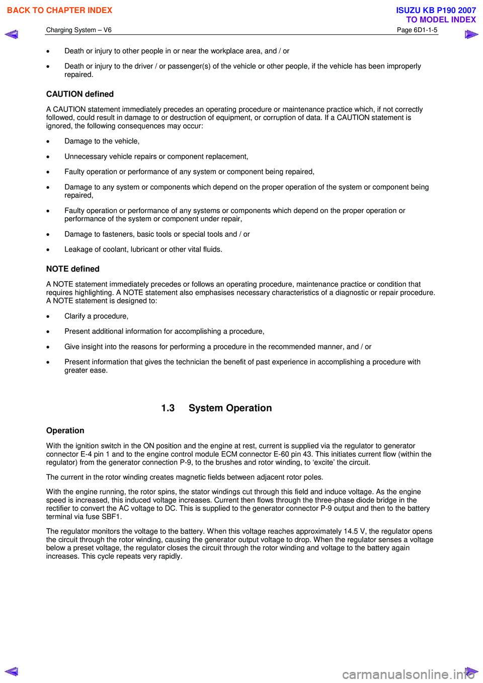
W ith the ignition switch in the ON position and the engine at rest, current is supplied via the regulator to generator
connector E-4 pin 1 and to the engine control module ECM connector E-60 pin 43. This initiates current flow (within the
regulator) from the generator connection P-9, to the brushes and rotor winding, to ‘excite’ the circuit.
The current in the rotor winding creates magnetic fields between adjacent rotor poles.
W ith the engine running, the rotor spins, the stator windings cut through this field and induce voltage. As the engine
speed is increased, this induced voltage increases. Current then flows through the three-phase diode bridge in the
rectifier to convert the AC voltage to DC. This is supplied to the generator connector P-9 output and then to the battery
terminal via fuse SBF1.
The regulator monitors the voltage to the battery. W hen this voltage reaches approximately 14.5 V, the regulator opens
the circuit through the rotor winding, causing the generator output voltage to drop. W hen the regulator senses a voltage
below a preset voltage, the regulator closes the circuit through the rotor winding and voltage to the battery again
increases. This cycle repeats very rapidly.
BACK TO CHAPTER INDEX
TO MODEL INDEX
ISUZU KB P190 2007
Page 3609 of 6020
Starting System – V6 Page 6D1-2–1
6D1-2
Starting System – V6
ATTENTION
Before performing any service operation or other procedure described in this Section, refer to 1.1
WARNING, CAUTION and NOTES for correct workshop practices with regard to safety and/or property
damage.
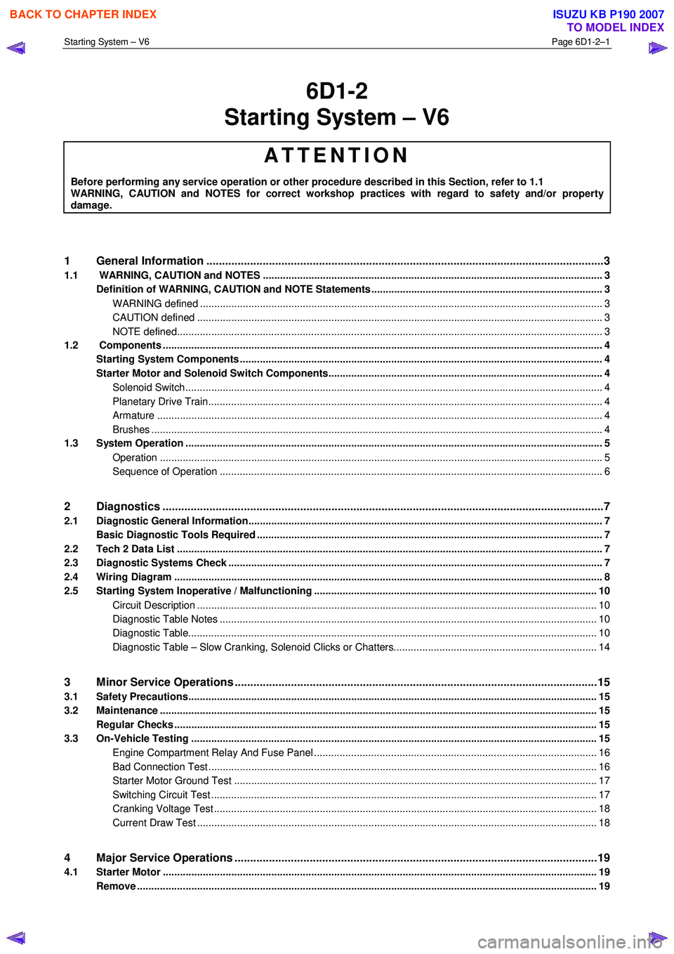
1 General Information ............................................................................................................ ...................3
1.1 WARNING, CAUTION and NOTES .................................................................................................... ................... 3
Definition of WARNING, CAUTION and NOTE Statements ............................................................................. .... 3
WARNING defined ............................................................................................................................................. 3
CAUTION defined .............................................................................................................................................. 3
NOTE defined..................................................................................................................................................... 3
1.2 Components .......................................................................................................................................................... 4
Starting System Components ............................................................................................................................... 4
Starter Motor and Solenoid Switch Components................................................................................... ............. 4
Solenoid Switch.................................................................................................................................................. 4
Planetary Drive Train.......................................................................................................... ................................ 4
Armature ............................................................................................................................................................ 4
Brushes .............................................................................................................................................................. 4
1.3 System Operation .................................................................................................................................................. 5
Operation ...................................................................................................................... ..................................... 5
Sequence of Operation .......................................................................................................... ............................ 6
2 Diagnostics .............................................................................................................................................7
2.1 Diagnostic General Information............................................................................................................................ 7
Basic Diagnostic Tools Required ......................................................................................................................... 7
2.2 Tech 2 Data List ............................................................................................................... ...................................... 7
2.3 Diagnostic Systems Check ....................................................................................................... ............................ 7
2.4 Wiring Diagram ...................................................................................................................................................... 8
2.5 Starting System Inoperative / Malfunctioning ................................................................................... ................ 10
Circuit Description ............................................................................................................................................ 10
Diagnostic Table Notes ......................................................................................................... ........................... 10
Diagnostic Table............................................................................................................................................... 10
Diagnostic Table – Slow Cranking, Solenoid Clicks or Chatters.................................................................. ..... 14
3 Minor Service Operations ....................................................................................................................15
3.1 Safety Precautions............................................................................................................................................... 15
3.2 Maintenance ......................................................................................................................................................... 15
Regular Checks ................................................................................................................. ................................... 15
3.3 On-Vehicle Testing ............................................................................................................. ................................. 15
Engine Compartment Relay And Fuse Panel ........................................................................................ ........... 16
Bad Connection Test ........................................................................................................................................ 16
Starter Motor Ground Test ...................................................................................................... ......................... 17
Switching Circuit Test ....................................................................................................................................... 17
Cranking Voltage Test .......................................................................................................... ............................ 18
Current Draw Test ............................................................................................................................................ 18
4 Major Service Operations ....................................................................................................................19
4.1 Starter Motor ........................................................................................................................................................ 19
Remove ................................................................................................................................................................. 19
BACK TO CHAPTER INDEX
TO MODEL INDEX
ISUZU KB P190 2007
Page 3619 of 6020
Starting System – V6 Page 6D1-2–11
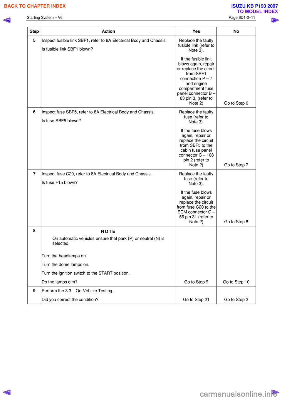
Step Action Yes No
5
Inspect fusible link SBF1, refer to 8A Electrical Body and Chassis.
Is fusible link SBF1 blown? Replace the faulty
fusible link (refer to Note 3).
If the fusible link
blows again, repair
or replace the circuit from SBF1
connection P – 7
and engine
compartment fuse
panel connector B – 63 pin 3, (refer to
Note 2) Go to Step 6
6 Inspect fuse SBF5, refer to 8A Electrical Body and Chassis.
Is fuse SBF5 blown? Replace the faulty
fuse (refer to Note 3).
If the fuse blows again, repair or
replace the circuit from SBF5 to the cabin fuse panel
connector C – 108
pin 2 (refer to Note 2) Go to Step 7
7
Inspect fuse C20, refer to 8A Electrical Body and Chassis.
Is fuse F15 blown? Replace the faulty
fuse (refer to Note 3).
If the fuse blows again, repair or
replace the circuit
from fuse C20 to the ECM connector C –
56 pin 31 (refer to Note 2) Go to Step 8
8 NOTE
On automatic vehicles ensure that park (P) or neutral (N) is
selected.
Turn the headlamps on.
Turn the dome lamps on.
Turn the ignition switch to the START position.
Do the lamps dim? Go to Step 9 Go to Step 10
9
Perform the 3.3 On-Vehicle Testing.
Did you correct the condition?
Go to Step 21 Go to Step 2
BACK TO CHAPTER INDEX
TO MODEL INDEX
ISUZU KB P190 2007
Page 3620 of 6020
Starting System – V6 Page 6D1-2–12
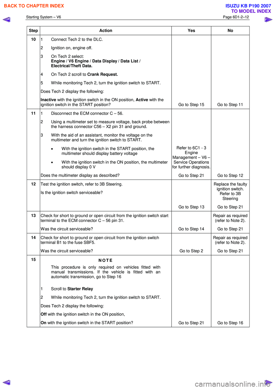
Step Action Yes No
10
1 Connect Tech 2 to the DLC.
2 Ignition on, engine off.
3 On Tech 2 select: Engine / V6 Engine / Data Display / Data List /
Electrical/Theft Data.
4 On Tech 2 scroll to Crank Request.
5 W hile monitoring Tech 2, turn the ignition switch to START.
Does Tech 2 display the following:
Inactive with the ignition switch in the ON position, Active with the
ignition switch in the START position? Go to Step 15 Go to Step 11
11 1 Disconnect the ECM connector C – 56.
2 Using a multimeter set to measure voltage, back probe between the harness connector C56 – X2 pin 31 and ground.
3 W ith the aid of an assistant, monitor the voltage on the multimeter and turn the ignition switch to START.
• W ith the ignition switch in the START position, the
multimeter should display battery voltage
• W ith the ignition switch in the ON position, the multimeter
should display 0 V
Does the multimeter display as described? Refer to 6C1 - 3
Engine
Management – V6 – Service Operations
for further diagnosis.
Go to Step 21 Go to Step 12
12 Test the ignition switch, refer to 3B Steering.
Is the ignition switch serviceable?
Go to Step 13 Replace the faulty
ignition switch. Refer to 3B
Steering
Go to Step 21
13 Check for short to ground or open circuit from the ignition switch start
terminal to the ECM connector C – 56 pin 31.
W as the circuit serviceable? Go to Step 14 Repair as required
(refer to Note 2).
Go to Step 21
14 Check for short to ground or open circuit from the ignition switch
terminal B1 to the fuse SBF5.
W as the circuit serviceable? Go to Step 2 Repair as required
(refer to Note 2).
Go to Step 21
15 NOTE
This procedure is only required on vehicles fitted with
manual transmissions. If the vehicle is fitted with an
automatic transmission, go to Step 16
1 Scroll to Starter Relay
2 W hile monitoring Tech 2, turn the ignition switch to START.
Does Tech 2 display the following:
Off with the ignition switch in the ON position,
On with the ignition switch in the START position?
Go to Step 21 Go to Step 16
BACK TO CHAPTER INDEX
TO MODEL INDEX
ISUZU KB P190 2007
Page 3624 of 6020
Starting System – V6 Page 6D1-2–16
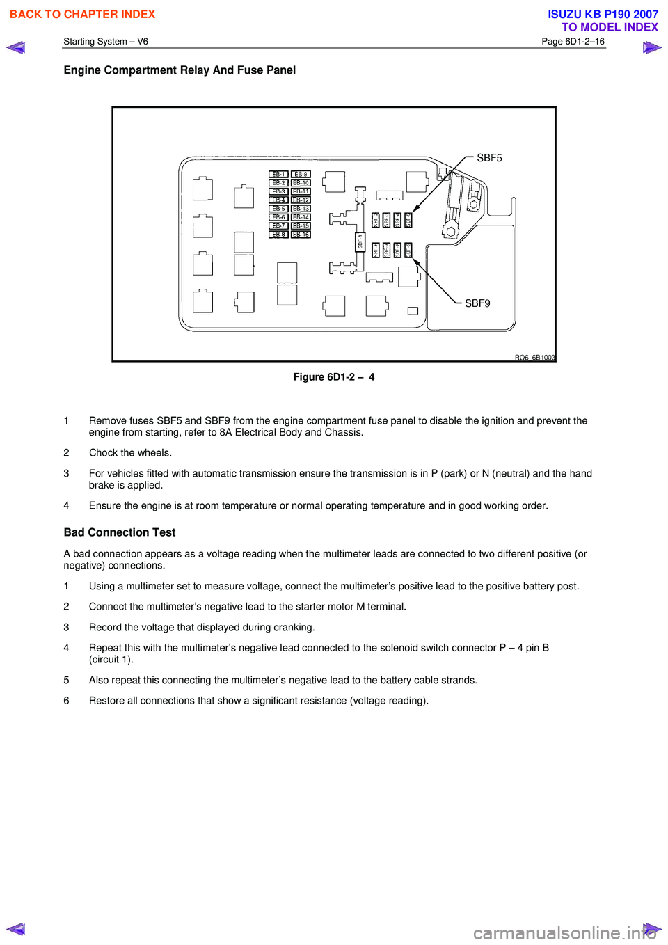
Engine Compartment Relay And Fuse Panel
Figure 6D1-2 – 4
1 Remove fuses SBF5 and SBF9 from the engine compartment fuse panel to disable the ignition and prevent the engine from starting, refer to 8A Electrical Body and Chassis.
2 Chock the wheels.
3 For vehicles fitted with automatic transmission ensure the transmission is in P (park) or N (neutral) and the hand brake is applied.
4 Ensure the engine is at room temperature or normal operating temperature and in good working order.
Bad Connection Test
A bad connection appears as a voltage reading when the multimeter leads are connected to two different positive (or
negative) connections.
1 Using a multimeter set to measure voltage, connect the multimeter’s positive lead to the positive battery post.
2 Connect the multimeter’s negative lead to the starter motor M terminal.
3 Record the voltage that displayed during cranking.
4 Repeat this with the multimeter’s negative lead connected to the solenoid switch connector P – 4 pin B (circuit 1).
5 Also repeat this connecting the multimeter’s negative lead to the battery cable strands.
6 Restore all connections that show a significant resistance (voltage reading).
BACK TO CHAPTER INDEX
TO MODEL INDEX
ISUZU KB P190 2007
Page 3644 of 6020
Battery Page 6D1-3–4
• Clarify a procedure,
• Present additional information for accomplishing a procedure,
• Give insight into the reasons for performing a procedure in the recommended manner, and / or
Present information that gives the technician the benefit of past experience in accomplishing a procedure with greater
ease.
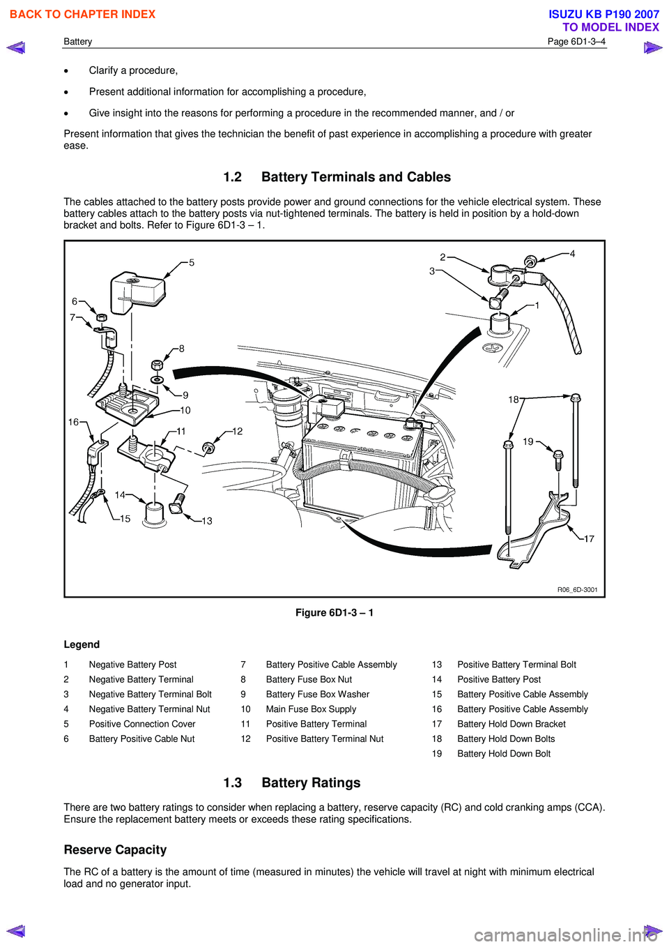
1.2 Battery Terminals and Cables
The cables attached to the battery posts provide power and ground connections for the vehicle electrical system. These
battery cables attach to the battery posts via nut-tightened terminals. The battery is held in position by a hold-down
bracket and bolts. Refer to Figure 6D1-3 – 1.
Figure 6D1-3 – 1
Legend
1 Negative Battery Post
2 Negative Battery Terminal
3 Negative Battery Terminal Bolt
4 Negative Battery Terminal Nut
5 Positive Connection Cover
6 Battery Positive Cable Nut 7 Battery Positive Cable Assembly
8 Battery Fuse Box Nut
9 Battery Fuse Box Washer
10 Main Fuse Box Supply
11 Positive Battery Terminal
12 Positive Battery Terminal Nut 13 Positive Battery Terminal Bolt
14 Positive Battery Post
15 Battery Positive Cable Assembly
16 Battery Positive Cable Assembly
17 Battery Hold Down Bracket
18 Battery Hold Down Bolts
19 Battery Hold Down Bolt
1.3 Battery Ratings
There are two battery ratings to consider when replacing a battery, reserve capacity (RC) and cold cranking amps (CCA).
Ensure the replacement battery meets or exceeds these rating specifications.
Reserve Capacity
The RC of a battery is the amount of time (measured in minutes) the vehicle will travel at night with minimum electrical
load and no generator input.
BACK TO CHAPTER INDEX
TO MODEL INDEX
ISUZU KB P190 2007
Page 3651 of 6020
Battery Page 6D1-3–11
b W ait 15 seconds for the battery to recover.
8 If possible, set the selector to 50% of rapid discharge current (or three times the 20 hour discharge rate).
9 Apply the load test for 10 seconds and record the battery voltage. If one cell is faulty it will gas excessively or overheat. This indicates a faulty battery.
10 Recharge the battery if the voltage is at or below the minimum voltage specified by the HRD manufacturer (or 9.6 V).
11 Replace the battery if the voltage is below the minimum voltage specified by the HRD manufacturer (or below 9.6 V after the battery is charged and the test is repeated). Refer to 4.1 Battery.
12 Connect the battery positive terminal.
13 Connect the battery negative terminal.
Alternate Load Test
If HRD test equipment is not available, test the battery as follows:
1 Read and obey the safety precautions for working with batteries, refer to 2 Safety Precautions.
2 Ensure the state of the battery is at least 65% charged. Refer to 3.3 Hydrometer Test.
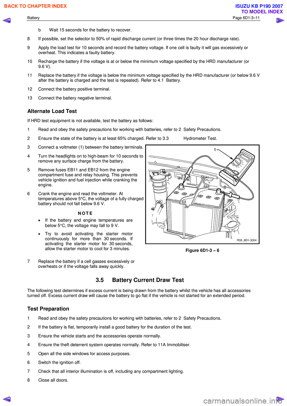
3 Connect a voltmeter (1) between the battery terminals.
4 Turn the headlights on to high-beam for 10 seconds to remove any surface charge from the battery.
5 Remove fuses EB11 and EB12 from the engine compartment fuse and relay housing. This prevents
vehicle ignition and fuel injection while cranking the
engine.
6 Crank the engine and read the voltmeter. At temperatures above 5°C, the voltage of a fully charged
battery should not fall below 9.6 V.
NOTE
• If the battery and engine temperatures are
below 5 °C, the voltage may fall to 9 V.
• Try to avoid activating the starter motor
continuously for more than 30 seconds. If
activating the starter motor for 30 seconds,
allow the starter motor to cool for 3 minutes.
7 Replace the battery if a cell gasses excessively or overheats or if the voltage falls away quickly.
Figure 6D1-3 – 6
3.5 Battery Current Draw Test
The following test determines if excess current is being drawn from the battery whilst the vehicle has all accessories
turned off. Excess current draw will cause the battery to go flat if the vehicle is not started for an extended period.
Test Preparation
1 Read and obey the safety precautions for working with batteries, refer to 2 Safety Precautions.
2 If the battery is flat, temporarily install a good battery for the duration of the test.
3 Ensure the vehicle starts and the accessories operate normally.
4 Ensure the theft deterrent system operates normally. Refer to 11A Immobiliser.
5 Open all the side windows for access purposes.
6 Switch the ignition off.
7 Check that all interior illumination is off, including any compartment lighting.
8 Close all doors.
BACK TO CHAPTER INDEX
TO MODEL INDEX
ISUZU KB P190 2007
Page 3652 of 6020
Battery Page 6D1-3–12
9 Lock the doors and activate the theft deterrent system to arm the vehicle.
10 If the multimeter contains fuses, check they are serviceable.
Test Procedure
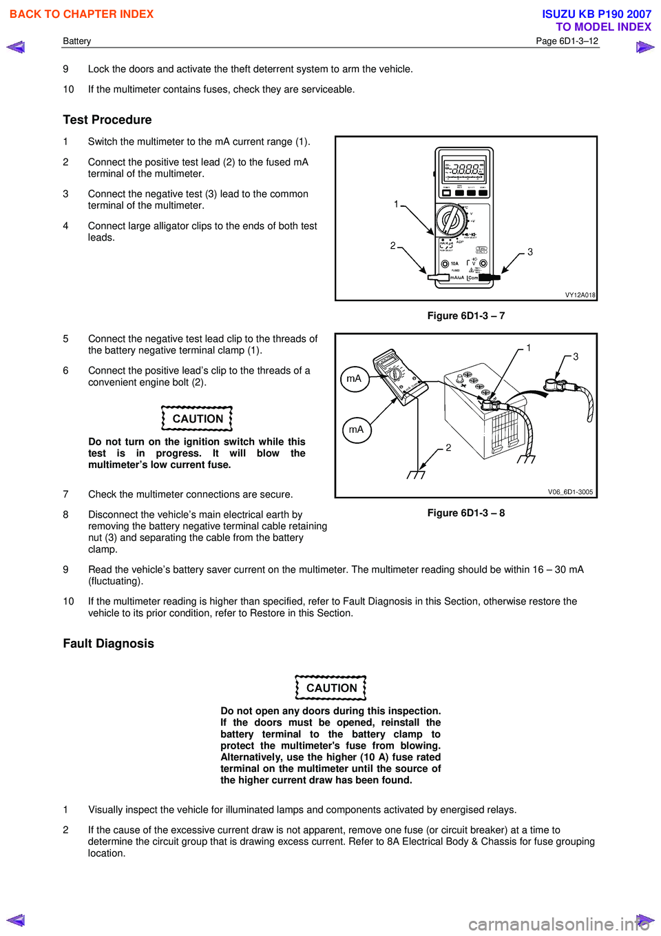
1 Switch the multimeter to the mA current range (1).
2 Connect the positive test lead (2) to the fused mA terminal of the multimeter.
3 Connect the negative test (3) lead to the common terminal of the multimeter.
4 Connect large alligator clips to the ends of both test leads.
Figure 6D1-3 – 7
5 Connect the negative test lead clip to the threads of the battery negative terminal clamp (1).
6 Connect the positive lead’s clip to the threads of a convenient engine bolt (2).
Do not turn on the ignition switch while this
test is in progress. It will blow the
multimeter’s low current fuse.
7 Check the multimeter connections are secure.
8 Disconnect the vehicle’s main electrical earth by removing the battery negative terminal cable retaining
nut (3) and separating the cable from the battery
clamp.
Figure 6D1-3 – 8
9 Read the vehicle’s battery saver current on the multimeter. The multimeter reading should be within 16 – 30 mA (fluctuating).
10 If the multimeter reading is higher than specified, refer to Fault Diagnosis in this Section, otherwise restore the vehicle to its prior condition, refer to Restore in this Section.
Fault Diagnosis
Do not open any doors during this inspection.
If the doors must be opened, reinstall the
battery terminal to the battery clamp to
protect the multimeter's fuse from blowing.
Alternatively, use the higher (10 A) fuse rated
terminal on the multimeter until the source of
the higher current draw has been found.
1 Visually inspect the vehicle for illuminated lamps and components activated by energised relays.
2 If the cause of the excessive current draw is not apparent, remove one fuse (or circuit breaker) at a time to determine the circuit group that is drawing excess current. Refer to 8A Electrical Body & Chassis for fuse grouping
location.
BACK TO CHAPTER INDEX
TO MODEL INDEX
ISUZU KB P190 2007