2007 ISUZU KB P190 fuse
[x] Cancel search: fusePage 3884 of 6020
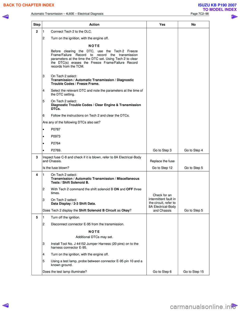
Automatic Transmission – 4L60E – Electrical Diagnosis Page 7C2–98
Step Action Yes No
2 1 Connect Tech 2 to the DLC.
2 Turn on the ignition, with the engine off.
NOTE
Before clearing the DTC, use the Tech 2 Freeze
Frame/Failure Record to record the transmission
parameters at the time the DTC set. Using Tech 2 to clear
the DTC(s) erases the Freeze Frame/Failure Record
records from the TCM.
3 On Tech 2 select: Transmission / Automatic Transmission / Diagnostic
Trouble Codes / Freeze Frame.
4 Select the relevant DTC and note the parameters at the time of the DTC setting.
5 On Tech 2 select:
Diagnostic Trouble Codes / Clear Engine & Transmission
DTCs.
6 Follow the instructions on Tech 2 and clear the DTCs.
Are any of the following DTCs also set?
• P0787
• P0973
• P2764
• P2769. Go to Step 3 Go to Step 4
3 Inspect fuse C-8 and check if it is blown, refer to 8A Electrical-Body
and Chassis.
Is the fuse blown? Replace the fuse
Go to Step 12 Go to Step 5
4 1 On Tech 2 select:
Transmission / Automatic Transmission / Miscellaneous
Tests / Shift Solenoid B.
2 With Tech 2 command the shift solenoid B ON and OFF three
times.
3 On Tech 2 select: Data Display / 2-3 Shift Data.
Does Tech 2 display the Shift Solenoid B Circuit as Okay ? Check for an
intermittent fault in the circuit, refer to
8A Electrical-Body
and Chassis Go to Step 5
5
1 Turn off the ignition.
2 Disconnect connector E-95 from the transmission.
NOTE
Additional DTCs may set.
3 Install Tool No. J 44152 Jumper Harness (20 pins) on to the harness connector E-95.
4 Turn on the ignition, with the engine off.
5 Using a test lamp, probe between connector E-95 pin 10 and a known ground.
Does the test lamp illuminate? Go to Step 6 Go to Step 15
BACK TO CHAPTER INDEX
TO MODEL INDEX
ISUZU KB P190 2007
Page 3898 of 6020
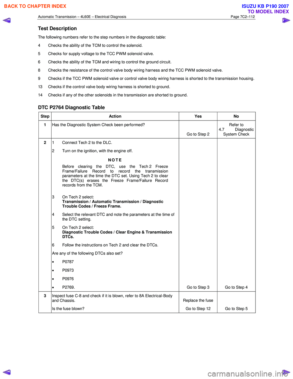
Automatic Transmission – 4L60E – Electrical Diagnosis Page 7C2–112
Test Description
The following numbers refer to the step numbers in the diagnostic table:
4 Checks the ability of the TCM to control the solenoid.
5 Checks for supply voltage to the TCC PWM solenoid valve.
6 Checks the ability of the TCM and wiring to control the ground circuit.
8 Checks the resistance of the control valve body wiring harness and the TCC PW M solenoid valve.
9 Checks if the TCC PWM solenoid valve or control valve body wiring harness is shorted to the transmission housing.
13 Checks if the control valve body wiring harness is shorted to ground.
14 Checks if any of the other solenoids in the transmission are shorted to ground.
DTC P2764 Diagnostic Table
Step Action Yes No
1 Has the Diagnostic System Check been performed?
Go to Step 2 Refer to
4.7 Diagnostic System Check
2 1 Connect Tech 2 to the DLC.
2 Turn on the ignition, with the engine off.
NOTE
Before clearing the DTC, use the Tech 2 Freeze
Frame/Failure Record to record the transmission
parameters at the time the DTC set. Using Tech 2 to clear
the DTC(s) erases the Freeze Frame/Failure Record
records from the TCM.
3 On Tech 2 select: Transmission / Automatic Transmission / Diagnostic
Trouble Codes / Freeze Frame.
4 Select the relevant DTC and note the parameters at the time of the DTC setting.
5 On Tech 2 select:
Diagnostic Trouble Codes / Clear Engine & Transmission
DTCs.
6 Follow the instructions on Tech 2 and clear the DTCs.
Are any of the following DTCs also set?
• P0787
• P0973
• P0976
• P2769. Go to Step 3 Go to Step 4
3 Inspect fuse C-8 and check if it is blown, refer to 8A Electrical-Body
and Chassis.
Is the fuse blown? Replace the fuse
Go to Step 12 Go to Step 5
BACK TO CHAPTER INDEX
TO MODEL INDEX
ISUZU KB P190 2007
Page 3903 of 6020
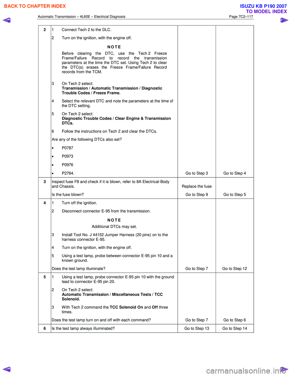
Automatic Transmission – 4L60E – Electrical Diagnosis Page 7C2–117
2 1 Connect Tech 2 to the DLC.
2 Turn on the ignition, with the engine off.
NOTE
Before clearing the DTC, use the Tech 2 Freeze
Frame/Failure Record to record the transmission
parameters at the time the DTC set. Using Tech 2 to clear
the DTC(s) erases the Freeze Frame/Failure Record
records from the TCM.
3 On Tech 2 select: Transmission / Automatic Transmission / Diagnostic
Trouble Codes / Freeze Frame.
4 Select the relevant DTC and note the parameters at the time of the DTC setting.
5 On Tech 2 select:
Diagnostic Trouble Codes / Clear Engine & Transmission
DTCs.
6 Follow the instructions on Tech 2 and clear the DTCs.
Are any of the following DTCs also set?
• P0787
• P0973
• P0976
• P2764.
Go to Step 3 Go to Step 4
3 Inspect fuse F8 and check if it is blown, refer to 8A Electrical-Body
and Chassis.
Is the fuse blown? Replace the fuse
Go to Step 9 Go to Step 5
4 1 Turn off the ignition.
2 Disconnect connector E-95 from the transmission.
NOTE
Additional DTCs may set.
3 Install Tool No. J 44152 Jumper Harness (20 pins) on to the harness connector E-95.
4 Turn on the ignition, with the engine off.
5 Using a test lamp, probe between connector E-95 pin 10 and a known ground.
Does the test lamp illuminate? Go to Step 7 Go to Step 12
5 1 Using a test lamp, probe connector E-95 pin 10 with the ground
lead to connector E-95 pin 20.
2 On Tech 2 select: Automatic Transmission / Miscellaneous Tests / TCC
Solenoid.
3 With Tech 2 command the TCC Solenoid On and
Off three
times.
Does the test lamp turn on and off with each command? Go to Step 7 Go to Step 6
6 Is the test lamp always illuminated? Go to Step 13 Go to Step 14
BACK TO CHAPTER INDEX
TO MODEL INDEX
ISUZU KB P190 2007
Page 3957 of 6020
Automatic Transmission – 4L60E – On-vehicle Servicing Page 7C4–44
b Starter motor, refer to 6D1-2 Starting System.
b Rear propeller shaft and for 4WD front propeller shaft, refer to 4A Propeller Shaft.
6 On 4WD vehicle, disconnect the harness two clips from the upper side of the transfer case.
7 From within the starter motor access hole, remove the three bolts (2) attaching the torque converter to the flexplate and discard, refer to Figure 7C4 – 62.
8 Remove the transmission support, refer to 3.7 Transmission Support and Mount.
9 Disconnect the fuel and EVAP pipes three brackets and clips, refer to 6C Fuel System – V6.
Before lowering the transmission take care of
the following:
• Do not strain the harness and connector
as the connector pins could be
permanently damaged.
• Ensure the inlet manifold does not hit the
firewall.
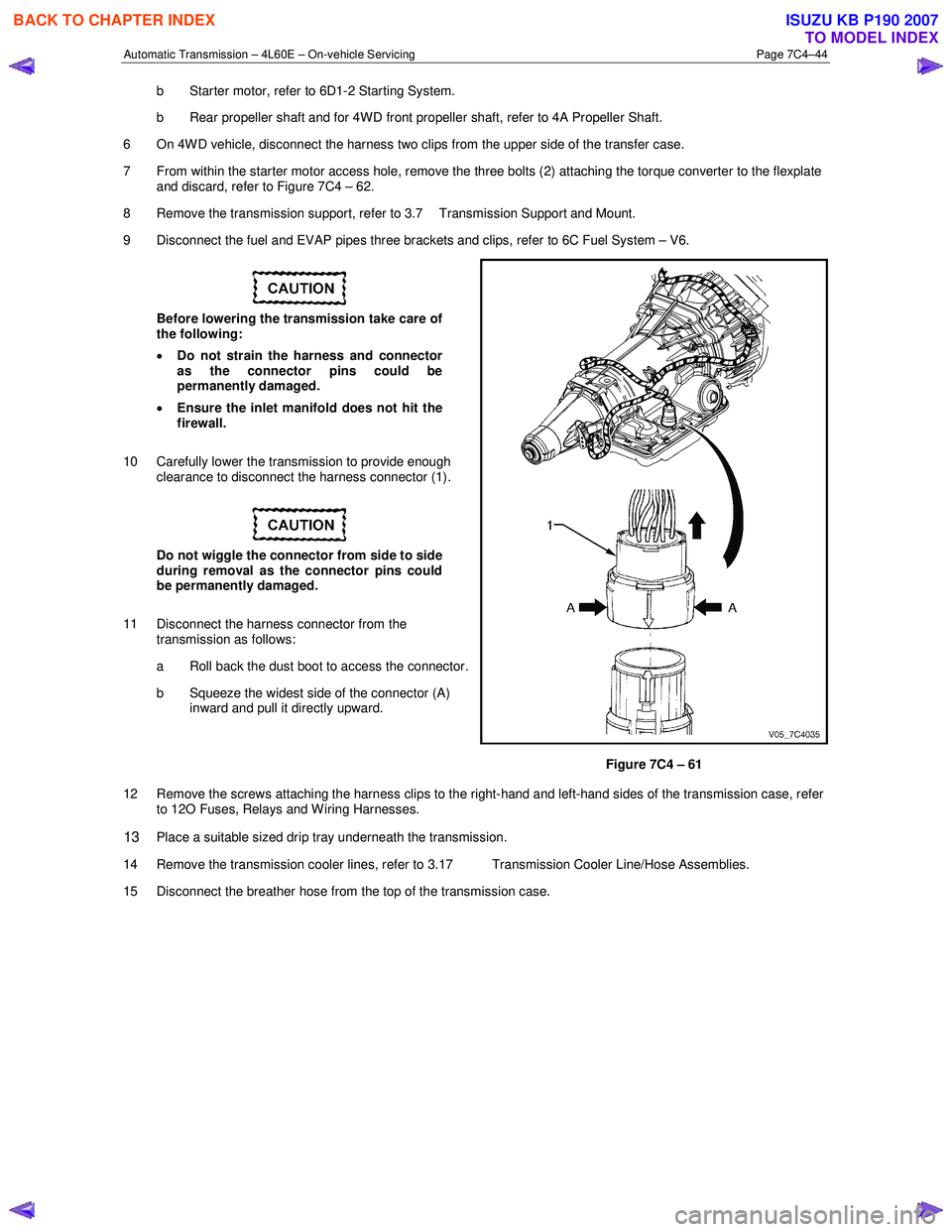
10 Carefully lower the transmission to provide enough clearance to disconnect the harness connector (1).
Do not wiggle the connector from side to side
during removal as the connector pins could
be permanently damaged.
11 Disconnect the harness connector from the transmission as follows:
a Roll back the dust boot to access the connector.
b Squeeze the widest side of the connector (A) inward and pull it directly upward.
Figure 7C4 – 61
12 Remove the screws attaching the harness clips to the right-hand and left-hand sides of the transmission case, refer to 12O Fuses, Relays and W iring Harnesses.
13 Place a suitable sized drip tray underneath the transmission.
14 Remove the transmission cooler lines, refer to 3.17 Transmission Cooler Line/Hose Assemblies.
15 Disconnect the breather hose from the top of the transmission case.
BACK TO CHAPTER INDEX
TO MODEL INDEX
ISUZU KB P190 2007
Page 3959 of 6020
Automatic Transmission – 4L60E – On-vehicle Servicing Page 7C4–46
Reinstall
1 If required on 4W D vehicle, reinstall the transfer case, refer to 7D Transfer Case and Adaptor Housing.
2 Ensure the transmission and the engine mating surfaces are clean and free of burrs.
3 Lubricate the torque converter spigot (7) with a small amount of high temperature wheel bearing grease, refer to Figure 7C4 – 62.
4 Install a new filler tube seal into the transmission case.
Support the transmission while installing the
attaching bolts to avoid damage to the torque
converter and flexplate. Do not have the
transmission hanging.
5 Bring the transmission up to the engine, inserting the filler tube and ensuring the locating dowels completely enter the torque converter housing.
6 Reconnect the breather hose to the top of the transmission case.
NOTE
The bolts attaching the torque converter housing
are facing forward except for the bolt in position ℑ
which is facing rearward.
7 With the transmission supported, install the bolt (1), nine places, attaching the torque converter housing to the engine and tighten to the correct torque specification following the sequence shown in
within Figure 7C4 – 62.
Torque converter housing attaching
bolt torque specification .......................... 52.0 – 66.0 Nm
8 Remove the access hole cover plate from the lower surface of the housing and push the torque converter forward to meet the flexplate, then hand start three new bolts (2) before tightening to the correct torque specification.
Reinstall the access hole cover plate.
Torque converter to flexplate attaching
bolt torque specification .......................... 60.0 – 70.0 Nm
9 Reinstall the bolt (3) and torque converter cover (4) on the transmission right-hand side and the bolt (5) and torque converter cover (6) on the transmission left-hand side, tighten the bolts to the correct torque specification.
Torque converter cover attaching
bolt torque specification .......................... 12.0 – 16.0 Nm
10 Reinstall the transmission fluid lines, refer to 3.17 Transmission Cooler Line/Hose Assemblies.
Prior to connecting the harness connector to
the transmission, check that all pins and
seals are in sound condition and the dust
boot is not torn or damaged.
11 Reconnect the transmission harness connector to the transmission as follows: a Push straight down on the connector body until a click is heard.
b Reinstall the dust boot ensuring it is correctly located.
12 Attach the harness clips to the right-hand and left-hand sides of the transmission case, refer to 12O Fuses, Relays and Wiring Harnesses.
13 On 4WD vehicle, connect the harness two clips from the upper side of the transfer case.
BACK TO CHAPTER INDEX
TO MODEL INDEX
ISUZU KB P190 2007
Page 3984 of 6020
7A2-18 TRANSMISSION CONTROL SYSTEM (AW30–40LE)
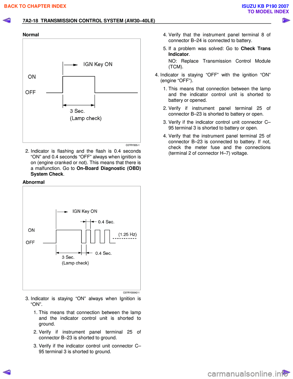
Normal
C07RY005-1
2. Indicator is flashing and the flash is 0.4 seconds
“ON” and 0.4 seconds “OFF” always when ignition is
on (engine cranked or not). This means that there is
a malfunction. Go to On-Board Diagnostic (OBD)
System Check .
Abnormal
C07RY00042-1
3. Indicator is staying “ON” always when Ignition is
“ON”.
1. This means that connection between the lamp
and the indicator control unit is shorted to
ground.
2. Verify if instrument panel terminal 25 o
f
connector B–23 is shorted to ground.
3. Verify if the indicator control unit connector C–
95 terminal 3 is shorted to ground.
4. Verify that the instrument panel terminal 8 o
f
connector B–24 is connected to battery.
5. If a problem was solved: Go to Check Trans
Indicator .
NO: Replace Transmission Control Module
(TCM).
4. Indicator is staying “OFF” with the ignition “ON”
(engine “OFF”).
1. This means that connection between the lamp
and the indicator control unit is shorted to
battery or opened.
2. Verify if instrument panel terminal 25 o
f
connector B–23 is shorted to battery or open.
3. Verify if the indicator control unit connector C–
95 terminal 3 is shorted to battery or open.
4. Verify that the instrument panel terminal 25 o
f
connector B–23 is connected to battery. If not,
check the meter fuse and the connections
(terminal 2 of connector H–7) voltage.
BACK TO CHAPTER INDEX
TO MODEL INDEX
ISUZU KB P190 2007
Page 4002 of 6020
7A2-36 TRANSMISSION CONTROL SYSTEM (AW30–40LE)
Trouble Code Clear Method:
If you have Tech 2:
Follow the procedure "DIAGNOSIS WITH TECH 2" in
this manual.
If you have no Tech 2:
Remove ECM (B) fuse (10A) for at least 10 seconds
with the ignition switched off.
NOTE:
If you clear the DTC you will not be able to read an
y
codes recorded during the last occurrence.
To use the DTC again to identify a problem, you will
need to reproduce the fault or the problem. This ma
y
require a new test drive or just turning the key switch on
(this depends on the nature of the fault).
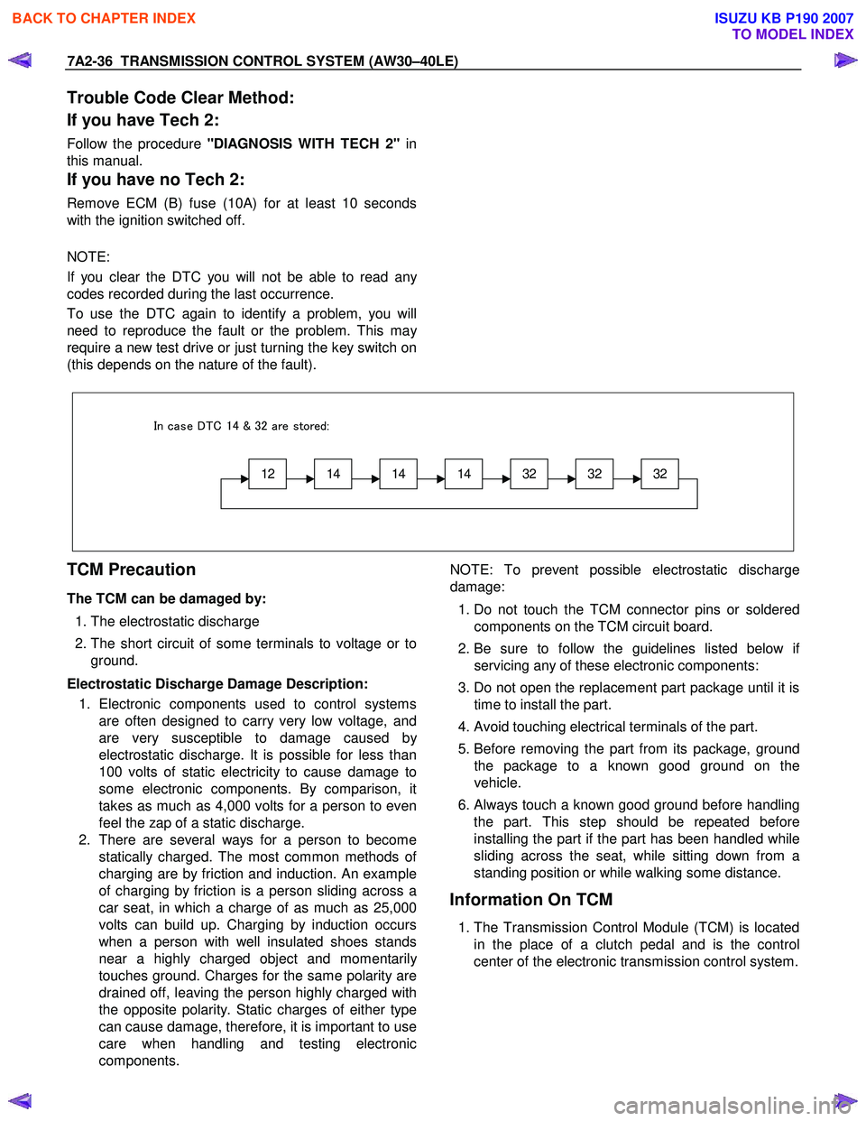
12141414323232
In case DTC 14 & 32 are stored:
TCM Precaution
The TCM can be damaged by:
1. The electrostatic discharge
2. The short circuit of some terminals to voltage or to
ground.
Electrostatic Discharge Damage Description: 1. Electronic components used to control systems are often designed to carry very low voltage, and
are very susceptible to damage caused b
y
electrostatic discharge. It is possible for less than
100 volts of static electricity to cause damage to
some electronic components. By comparison, it
takes as much as 4,000 volts for a person to even
feel the zap of a static discharge.
2. There are several ways for a person to become statically charged. The most common methods o
f
charging are by friction and induction. An example
of charging by friction is a person sliding across a
car seat, in which a charge of as much as 25,000
volts can build up. Charging by induction occurs
when a person with well insulated shoes stands
near a highly charged object and momentaril
y
touches ground. Charges for the same polarity are
drained off, leaving the person highly charged with
the opposite polarity. Static charges of either type
can cause damage, therefore, it is important to use
care when handling and testing electronic
components.
NOTE: To prevent possible electrostatic discharge
damage:
1. Do not touch the TCM connector pins or soldered
components on the TCM circuit board.
2. Be sure to follow the guidelines listed below i
f
servicing any of these electronic components:
3. Do not open the replacement part package until it is time to install the part.
4. Avoid touching electrical terminals of the part.
5. Before removing the part from its package, ground
the package to a known good ground on the
vehicle.
6.
Always touch a known good ground before handling
the part. This step should be repeated before
installing the part if the part has been handled while
sliding across the seat, while sitting down from a
standing position or while walking some distance.
Information On TCM
1. The Transmission Control Module (TCM) is located
in the place of a clutch pedal and is the control
center of the electronic transmission control system.
BACK TO CHAPTER INDEX
TO MODEL INDEX
ISUZU KB P190 2007
Page 4019 of 6020
TRANSMISSION CONTROL SYSTEM (AW30–40LE) 7A2-53
• No L-up solenoid functional failure detection.
• Check Trans “ON”.
• DTC stored.
• MIL request “ON”. (EURO 4 only)
Conditions For Clearing The DTC
• The DTC can be cleared from the TCM history by
using a scan tool.
• The DTC will be cleared from history when the
vehicle has achieved 40 warm-up cycles without a
failure reported.
•
After more than 1 second has elapsed after the
ignition key has been turned “ON”, short between
No.11 and No.4 (ground) of DLC (Data Link
Connector). Then, after 1 second, but within 6
seconds, discontinue shorting.
Diagnostic Aids
•
Inspect the wiring for poor electrical connection at the
TCM. Look for possible bent, backed out, deformed
or damaged terminals. Check for weak terminal
tension as well. Also check for a chafed wire that
could short to bare metal or other wiring. Inspect for a
broken wire inside the insulation.
• W hen diagnosing for a possible intermittent short o
r
open condition, move the wiring harness while
observing test equipment for a change.
• Check oil temperature sensor for proper mounting
and adjustment.
Circuit/System Testing DTC P0713
Step Action Value(s) YES NO
1
W as the On-Board Diagnostic (OBD) System Check
performed ? — Go to
Step 2 Go to OBD
System check
2 Perform the transmission fluid checking procedure. Refer to Checking Transmission Fluid Level and
condition Automatic Transmission 7A section.
W as the fluid checking procedure performed? — Go to
Step 3 Refer to
checking
Transmission
Fluid Level and Condition
Automatic
Transmission
(AW 30-40LE) section
3 1. Lift the driving wheels.
2. Start the engine and place the select lever in D
position.
3. W ait for 15 minutes.
Does a scan tool indicate DTC P0713? — Go to
Step 4 Refer to
Diagnostic Aids
4 Observe the voltage of the oil temperature sensor on the Tech 2 data.
1. Turn “OFF” the ignition.
2. Disconnect the oil temperature sensor connector
E-83
3. Install a fused jumper wire from terminal E83-2 to E83-1 on the transmission harness.
4. Turn “ON” the ignition.
Does a scan tool indicate specified value? About 0V Go to
Step 5 Go to Step 6
5 Replace the transmission fluid temperature sensor.
If the action complete? — Go to
Step 9 —
BACK TO CHAPTER INDEX
TO MODEL INDEX
ISUZU KB P190 2007