Page 4940 of 6020

8A-2 ELECTRICAL-BODY AND CHASSIS
PAGE
Fuse Block Circuit (4JJ1-TC/4JK1-TC (RHD)) SOUTH AFRICA ...............................8A- 39
Fuse Block Circuit (4JJ1-TC/4JK1-TC (RHD)) EXCEPT SOUTH AFRICA ...............8A- 41
Fuse Block Circuit (4JJ1-TC/4JK1-TC) - (LHD) G.EXP .............................................8A- 43
Fuse Block Circuit (4JH1-TC) - (LHD) ........................................................................8A- 45
Fuse Block Circuit (4JA1T (L)) ...................................................................................8A- 47
Grounding Point ..............................................................................................................8 A- 49
Ground Point ...............................................................................................................8A- 49
Ground Point Location ...............................................................................................8A- 89
Cable Harness Routing ...................................................................................................8A- 91
Main Cable Harness (RHD)..........................................................................................8A- 91
Instrument Harness (RHD) ..........................................................................................8A- 92
Main Cable Harness (LHD) ..........................................................................................8A- 93
Instrument Harness (LHD) ..........................................................................................8A- 94
Engine Harness C24SE ...............................................................................................8A- 95
Engine Harness 4JJ1-TC/4JK1-TC ............................................................................8A- 96
Engine Harness 4JH1-TC/4JA1T (L) ...........................................................................8A- 97
Transmission Harness ...............................................................................................8A- 98
System Repair ................................................................................................................. .8A- 100
Start and Charging ......................................................................................................8A- 10 0
Engine Control Module (ECM) ...................................................................................8A- 111
Exhaust Gas Recirculation (EGR) & GLOW; 4JA1T (L) Only ...................................8A- 143
Lighting ...................................................................................................................... ..8A- 149
Front Fog Light ...........................................................................................................8A- 180
Rear Fog Light ............................................................................................................8A- 190
Headlight Leveling ......................................................................................................8A- 19 4
Illumination .................................................................................................................. 8A- 200
Hazard Warning Flasher, Turn Signal Light, Backup Light, Horn and Stoplight ....................................................................................................8A- 213
Dome Light, Spotlight, Map Light and Warning Buzzer ..........................................8A- 245
Windshield Wiper and Washer ..................................................................................8A- 264
Transmission Control Module (TCM) ........................................................................8A- 285
Manual Transmission Shift Assist .............................................................................8A- 298
Meter, Warning Light and Indicator Light .................................................................8A- 303
Heater and Air Conditioning ......................................................................................8A- 371
Power Door Lock ........................................................................................................8A- 386
BACK TO CHAPTER INDEX
TO MODEL INDEX
ISUZU KB P190 2007
Page 4942 of 6020

8A-4 ELECTRICAL-BODY AND CHASSIS
GENERAL INFORMATION
The body and chassis electrical system operates on a twelve volt power supply with negative ground polarity.
The main harness consists of the engine harness, the instrument harness, the body harness, and the chassis
harness.
The harnesses use a split corrugated tube to protect the wires from the elements.
W ire size is determined by current flow, circuit length, and voltage drop.
All wires have color-coded insulation.
W ire color-codes are shown in the circuit diagrams.
This makes it easier to trace circuits and to make the proper connections.
Each circuit consists of the following:
5. Power source – The battery and the alternator
5. W ires – To carry electrical current through the circuit
5. Fuses – To protect the circuit against current overload
5. Relays – To protect voltage drop between the battery and the circuit parts and to protect the switch points against burning
5. Switches – To open and close the circuit
5. Load – Any device, such as a light or motor, which converts the electrical current into useful work
5. Ground – To allow the current to flow back to the power source
BACK TO CHAPTER INDEX TO MODEL INDEXISUZU KB P190 2007
Page 4945 of 6020

ELECTRICAL-BODY AND CHASSIS 8A-7
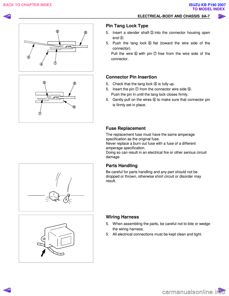
Pin Tang Lock Type
5. Insert a slender shaft 3into the connector housing open
end
4.
5. Push the tang lock
8flat (toward the wire side of the
connector).
Pull the wire
6 with pin 7free from the wire side of the
connector.
Connector Pin Insertion
5. Check that the tang lock 8 is fully up.
5. Insert the pin
7 from the connector wire side 9.
Push the pin in until the tang lock closes firmly.
5. Gently pull on the wires
6to make sure that connector pin
is firmly set in place.
Fuse Replacement
The replacement fuse must have the same amperage
specification as the original fuse.
Never replace a burn out fuse with a fuse of a different
amperage specification.
Doing so can result in an electrical fire or other serious circuit
damage.
Parts Handling
Be careful for parts handling and any part should not be
dropped or thrown, otherwise short circuit or disorder may
result.
Wiring Harness
5. W hen assembling the parts, be careful not to bite or wedge
the wiring harness.
5. All electrical connections must be kept clean and tight.
BACK TO CHAPTER INDEX TO MODEL INDEXISUZU KB P190 2007
Page 4953 of 6020

ELECTRICAL-BODY AND CHASSIS 8A-15
NormalBlown
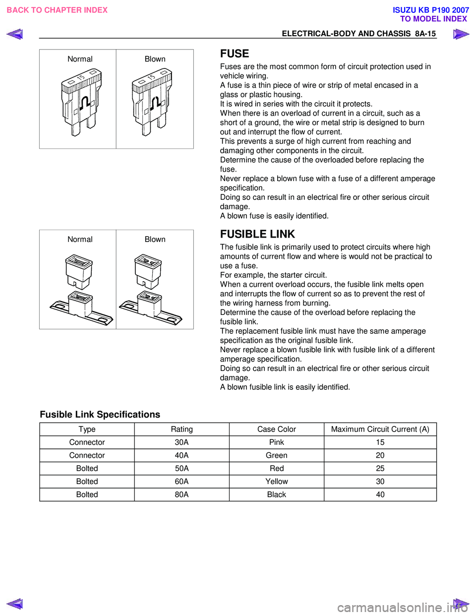
FUSE
Fuses are the most common form of circuit protection used in
vehicle wiring.
A fuse is a thin piece of wire or strip of metal encased in a
glass or plastic housing.
It is wired in series with the circuit it protects.
W hen there is an overload of current in a circuit, such as a
short of a ground, the wire or metal strip is designed to burn
out and interrupt the flow of current.
This prevents a surge of high current from reaching and
damaging other components in the circuit.
Determine the cause of the overloaded before replacing the
fuse.
Never replace a blown fuse with a fuse of a different amperage
specification.
Doing so can result in an electrical fire or other serious circuit
damage.
A blown fuse is easily identified.
Normal Blown
FUSIBLE LINK
The fusible link is primarily used to protect circuits where high
amounts of current flow and where is would not be practical to
use a fuse.
For example, the starter circuit.
W hen a current overload occurs, the fusible link melts open
and interrupts the flow of current so as to prevent the rest of
the wiring harness from burning.
Determine the cause of the overload before replacing the
fusible link.
The replacement fusible link must have the same amperage
specification as the original fusible link.
Never replace a blown fusible link with fusible link of a different
amperage specification.
Doing so can result in an electrical fire or other serious circuit
damage.
A blown fusible link is easily identified.
Fusible Link Specifications
Type Rating Case Color Maximum Circuit Current (A)
Connector 30A Pink 15
Connector 40A Green 20
Bolted 50A Red 25
Bolted 60A Yellow 30
Bolted 80A Black 40
BACK TO CHAPTER INDEX
TO MODEL INDEXISUZU KB P190 2007
Page 4964 of 6020
8A-26 ELECTRICAL-BODY AND CHASSIS
RELAY AND FUSE
RELAY AND FUSE BOX LOCATION (RHD)
RTW 780MF002301
BACK TO CHAPTER INDEXTO MODEL INDEXISUZU KB P190 2007
Page 4965 of 6020
ELECTRICAL-BODY AND CHASSIS 8A-27
RELAY AND FUSE BOX LOCATION (LHD)
RTW 78ALF000201
BACK TO CHAPTER INDEX TO MODEL INDEXISUZU KB P190 2007
Page 4966 of 6020
8A-28 ELECTRICAL-BODY AND CHASSIS
RELAY LOCATION
RELAY & FUSE BOX (ENGINE ROOM)
RHD
NO. RELEY (C24SE) RELAY (HFV6) RELAY (4JA1T(L)) RELAY
(4JJ1-TC/4JK1-TC)
X1 RELAY; TAIL LIGHT RELAY; FOG LIGHT ← ←
X2 RELAY; FUEL PUMP RELAY; TAIL LIGHT
← ←
X3 RELAY; HORN
← ← ←
X4 RELAY; DIMMER
← ← ←
X5
RELAY; GLOW
←
X6 RELAY; STARTER RELAY; H/LIGHT
← ←
X7 RELAY; H/LIGHT
(Except AUSTRALIA)
RELAY; COND FAN
(AUSTRALIA) RELAY; H/ LIGHT RELAY; CSD RELAY; STARTER CUT
X8
RELAY; STARTER
←
X9 RELAY; FRT FOG
LAMP
RELAY; COND FAN
X10 RELAY; COND FAN
RELAY;
TRANSMISSION
X11 RELAY; HEATER ← ← ←
X12 RELAY; STARTER CUT
(AUSTRALIA) RELAY; ECM MAIN
RELAY; ECM MAIN
X13 RELAY; STARTER CUT
(Except AUSTRALIA)
RELAY; H/LIGHT
(AUSTRALIA) RELAY; F/PUMP RELAY; COND FAN RELAY; F/PUMP
X14 RELAY; A/C COMP
← RELAY; STARTER CUT RELAY; A/C COMP
X15 RELAY; THERMO RELAY; STARTER RELAY; THERMO
←
BACK TO CHAPTER INDEX TO MODEL INDEXISUZU KB P190 2007
Page 4967 of 6020
ELECTRICAL-BODY AND CHASSIS 8A-29
RELAY LOCATION
RELAY & FUSE BOX (ENGINE ROOM)
LHD
NO. RELEY (C24SE) RELAY (HFV6) RELAY (4JH1-TC) RELAY (4JA1T(L)) RELAY
(4JJ1-TC/4JK1-TC)
X1 RELAY; TAIL LIGHT RELAY; FOG
LIGHT ←
← ←
X2 RELAY; FUEL
LIGHT RELAY; TAIL
LIGHT ←
← ←
X3 RELAY; HORN
← ← ← ←
X4 RELAY; DIMMER
← ← ← ←
X5
RELAY; GLOW
← ←
X6 RELAY; STARTER RELAY; H/LIGHT
← ← ←
X7 RELAY; H/LIGHT
RELAY; STARTER
CUT RELAY; CSD RELAY; STARTER
CUT
X8 RELAY; STARTER
← ←
X9 RELAY; FRT FOG
LIGHT
RELAY; COND
FAN
←
X10 RELAY; COND
FAN
RELAY;
TRANSMISSION
X11 RELAY; HEATER ← ← ← ←
X12
RELAY; ECM MAIN RELAY; ECM MAIN
←
X13 RELAY; STARTER
CUT RELAY; F/PUMP
RELAY; COND
FAN RELAY; F/PUMP
X14 RELAY; A/C COMP
← ← RELAY; STARTER
CUT RELAY; A/C COMP
X15 RELAY; THERMO RELAY; STARTER RELAY; THERMO RELAY; THERMO
←
BACK TO CHAPTER INDEXTO MODEL INDEXISUZU KB P190 2007