2007 ISUZU KB P190 fuse
[x] Cancel search: fusePage 3653 of 6020
Battery Page 6D1-3–13
3 W hen the circuit group is determined, install the fuse / circuit breaker and identify the specific circuit within this
group that is drawing the excess current. Disconnect the wiring harness connectors in this circuit group one at a
time. Refer to 8A Electrical Body & Chassis.
4 W hen the cause is disconnected, the multimeter reading should drop to the correct reading as outlined in Step 9 of the Test Procedure in this Section.
5 If required, remove the components in this circuit one at a time to determine the cause of the excessive standing current. Refer to 8A Electrical Body & Chassis.
6 Repair the fault, refer to 8A Electrical Body & Chassis.
7 Ensure any fuses, circuit breakers and connectors that have been removed are secure.
Restore
1 Reconnect the electrical earth cable to the battery terminal and tighten the nut to the correct torque specification.
Battery terminal nut
torque specification .....................................2.0 – 5.0 Nm
2 Disconnect the multimeter connections.
BACK TO CHAPTER INDEX
TO MODEL INDEX
ISUZU KB P190 2007
Page 3693 of 6020
Powertrain Interface Module – V6 Page 6E1–32
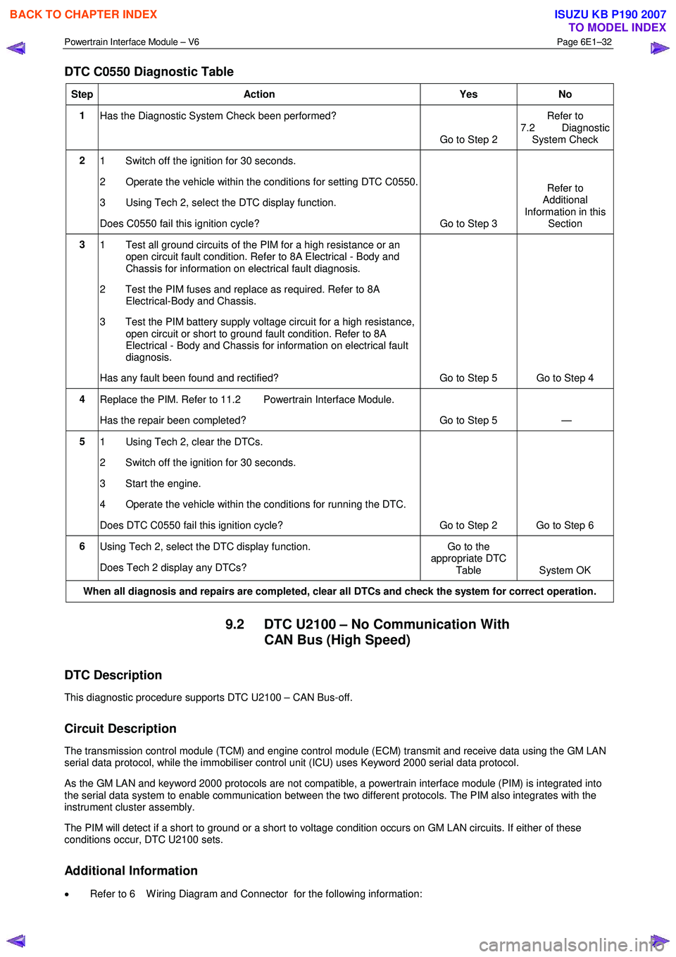
DTC C0550 Diagnostic Table
Step Action Yes No
1
Has the Diagnostic System Check been performed?
Go to Step 2 Refer to
7.2 Diagnostic System Check
2 1 Switch off the ignition for 30 seconds.
2 Operate the vehicle within the conditions for setting DTC C0550.
3 Using Tech 2, select the DTC display function.
Does C0550 fail this ignition cycle? Go to Step 3 Refer to
Additional
Information in this Section
3 1 Test all ground circuits of the PIM for a high resistance or an
open circuit fault condition. Refer to 8A Electrical - Body and
Chassis for information on electrical fault diagnosis.
2 Test the PIM fuses and replace as required. Refer to 8A Electrical-Body and Chassis.
3 Test the PIM battery supply voltage circuit for a high resistance, open circuit or short to ground fault condition. Refer to 8A
Electrical - Body and Chassis for information on electrical fault
diagnosis.
Has any fault been found and rectified? Go to Step 5 Go to Step 4
4 Replace the PIM. Refer to 11.2 Powertrain Interface Module.
Has the repair been completed? Go to Step 5 —
5 1 Using Tech 2, clear the DTCs.
2 Switch off the ignition for 30 seconds.
3 Start the engine.
4 Operate the vehicle within the conditions for running the DTC.
Does DTC C0550 fail this ignition cycle? Go to Step 2 Go to Step 6
6 Using Tech 2, select the DTC display function.
Does Tech 2 display any DTCs? Go to the
appropriate DTC
Table System OK
When all diagnosis and repairs are completed, clear all DTCs and check the system for correct operation.
9.2 DTC U2100 – No Communication With CAN Bus (High Speed)
DTC Description
This diagnostic procedure supports DTC U2100 – CAN Bus-off.
Circuit Description
The transmission control module (TCM) and engine control module (ECM) transmit and receive data using the GM LAN
serial data protocol, while the immobiliser control unit (ICU) uses Keyword 2000 serial data protocol.
As the GM LAN and keyword 2000 protocols are not compatible, a powertrain interface module (PIM) is integrated into
the serial data system to enable communication between the two different protocols. The PIM also integrates with the
instrument cluster assembly.
The PIM will detect if a short to ground or a short to voltage condition occurs on GM LAN circuits. If either of these
conditions occur, DTC U2100 sets.
Additional Information
• Refer to 6 W iring Diagram and Connector for the following information:
BACK TO CHAPTER INDEX
TO MODEL INDEX
ISUZU KB P190 2007
Page 3733 of 6020
Powertrain Interface Module – V6 Page 6E1–72
Remove
1 If replacing the PIM, reset the PIM prior to PIM removal. Refer to PIM Reset in this Section.
2 Turn the ignition switch off.
3 Remove Fuse EB-4, refer to 8A Electrical-Body and Chassis.
4 Remove the right-hand front body hinge pillar trim assembly, refer to 10 Cab.
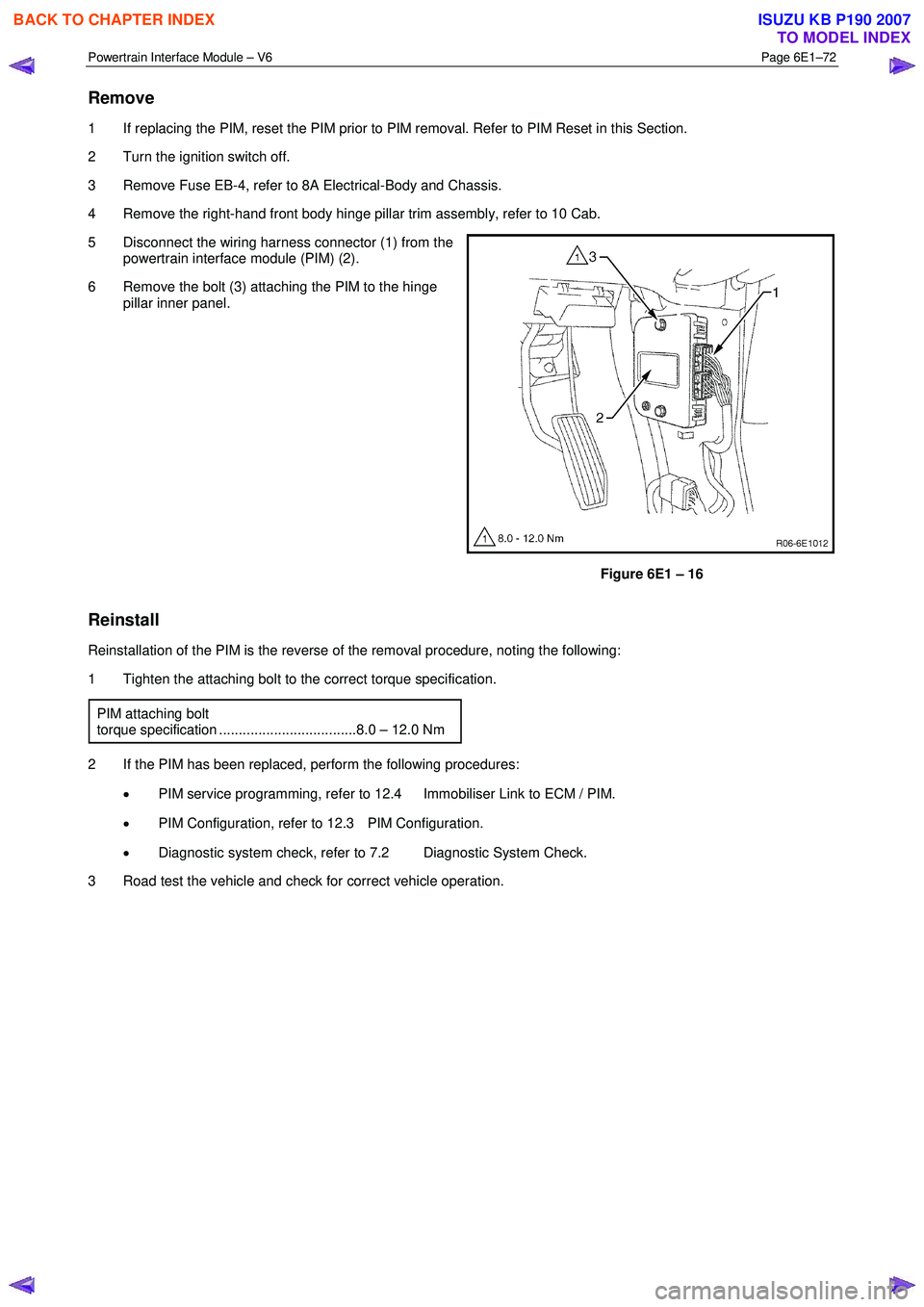
5 Disconnect the wiring harness connector (1) from the powertrain interface module (PIM) (2).
6 Remove the bolt (3) attaching the PIM to the hinge pillar inner panel.
Figure 6E1 – 16
Reinstall
Reinstallation of the PIM is the reverse of the removal procedure, noting the following:
1 Tighten the attaching bolt to the correct torque specification.
PIM attaching bolt
torque specification ...................................8.0 – 12.0 Nm
2 If the PIM has been replaced, perform the following procedures: • PIM service programming, refer to 12.4 Immobiliser Link to ECM / PIM.
• PIM Configuration, refer to 12.3 PIM Configuration.
• Diagnostic system check, refer to 7.2 Diagnostic System Check.
3 Road test the vehicle and check for correct vehicle operation.
BACK TO CHAPTER INDEX
TO MODEL INDEX
ISUZU KB P190 2007
Page 3814 of 6020
Automatic Transmission – 4L60E – Electrical Diagnosis Page 7C2–28
7 Ensure that all wiring harness connectors are fitted correctly and secure.
8 W hen steam or pressure cleaning vehicle components, such as engines, transmissions, etc., do not direct the cleaning nozzle at any system electrical wiring harness connectors or components.
9 Do not clear any DTCs unless instructed.
10 The fault must be present when using the Diagnostic Trouble Code (DTC) Diagnostic Tables. Otherwise, misdiagnosis or replacement of good parts may occur.
11 Do not touch any electronic control module connector pins or soldered components on the circuit board. This is required to avoid the possibility of electrostatic discharge damage.
12 Use only the test equipment specified in the diagnostic tables, as other test equipment may give incorrect results or damage good components.
13 Electronic control modules are designed to withstand normal current draws associated with vehicle operation. However, the following fault conditions or incorrect test procedure may overload internal control module circuits and
irreparably damage the control module:
• A short to voltage fault condition in any of the control module low reference circuits may cause internal and/or
sensor damage. Therefore, any short to voltage fault condition in the control module low reference circuits
must be rectified before replacing a faulty component.
• A short to ground fault condition in any of the control module 5 volts reference circuits may cause internal
control module and/or sensor damage. Therefore, any short to ground fault condition in the control module 5
volt reference circuits must be rectified before replacing a faulty component.
• W hen using a test light to test an electrical circuit, do not use any of the control module low reference circuits
or 5 volts reference circuits as a reference point. Otherwise, excessive current draw from the test light may
damage the control module.
14 Disregard DTCs that set while performing the following diagnostic Steps:
• Using the Tech 2 output control function, or
• Disconnecting a control module system sensor connector then switching the ignition ON.
15 After completing the required diagnostics and service operations, road test the vehicle to ensure correct system operation.
4.4 Preliminary Checks
The Preliminary Checks is a set of visual and physical checks or inspections that may quickly identify a control module
system fault condition:
1 Refer to relevant Service Techlines for information regarding the fault condition.
2 Ensure that the battery is fully charged.
3 Inspect the battery connections for corrosion or a loose terminal.
4 Ensure that all relevant control module system related fuses are serviceable.
5 Inspect for incorrect aftermarket theft deterrent devices, lights or mobile phone installation.
6 Ensure that there is no speaker magnet positioned too close to any electronic module that contains relays.
7 Inspect the system wiring harness for proper connections, pinches or cuts.
8 Ensure that all control module related electrical wiring connectors are fitted correctly.
9 Inspect the control module ground connections for corrosion, loose terminal or incorrect position.
10 Ensure that the resistance between the control module housing and the battery ground cable is less than 0.5 ohms.
11 Check that the control module and its mounting bracket is secure.
12 Check all control module related components for correct installation.
13 Check the control module and related wiring harness routing to ensure that no rubbing or cutting of the wiring harness by sharp body components can occur.
BACK TO CHAPTER INDEX
TO MODEL INDEX
ISUZU KB P190 2007
Page 3823 of 6020
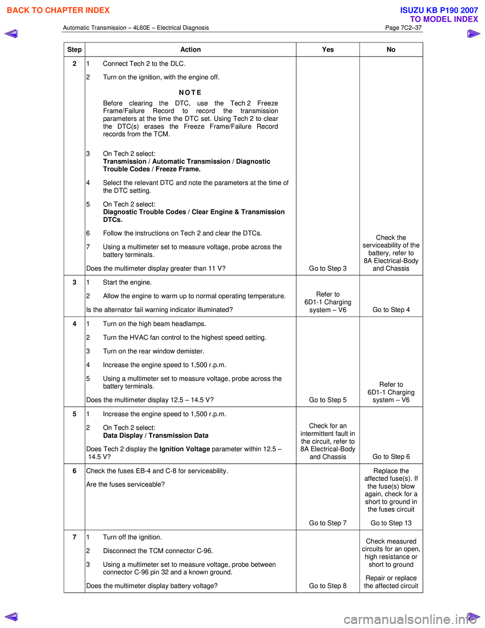
Automatic Transmission – 4L60E – Electrical Diagnosis Page 7C2–37
Step Action Yes No
2 1 Connect Tech 2 to the DLC.
2 Turn on the ignition, with the engine off.
NOTE
Before clearing the DTC, use the Tech 2 Freeze
Frame/Failure Record to record the transmission
parameters at the time the DTC set. Using Tech 2 to clear
the DTC(s) erases the Freeze Frame/Failure Record
records from the TCM.
3 On Tech 2 select: Transmission / Automatic Transmission / Diagnostic
Trouble Codes / Freeze Frame.
4 Select the relevant DTC and note the parameters at the time of the DTC setting.
5 On Tech 2 select:
Diagnostic Trouble Codes / Clear Engine & Transmission
DTCs.
6 Follow the instructions on Tech 2 and clear the DTCs.
7 Using a multimeter set to measure voltage, probe across the battery terminals.
Does the multimeter display greater than 11 V? Go to Step 3 Check the
serviceability of the battery, refer to
8A Electrical-Body and Chassis
3 1 Start the engine.
2 Allow the engine to warm up to normal operating temperature.
Is the alternator fail warning indicator illuminated? Refer to
6D1-1 Charging system – V6 Go to Step 4
4 1 Turn on the high beam headlamps.
2 Turn the HVAC fan control to the highest speed setting.
3 Turn on the rear window demister.
4 Increase the engine speed to 1,500 r.p.m.
5 Using a multimeter set to measure voltage, probe across the battery terminals.
Does the multimeter display 12.5 – 14.5 V? Go to Step 5 Refer to
6D1-1 Charging system – V6
5 1 Increase the engine speed to 1,500 r.p.m.
2 On Tech 2 select: Data Display / Transmission Data
Does Tech 2 display the Ignition Voltage parameter within 12.5 –
14.5 V? Check for an
intermittent fault in the circuit, refer to
8A Electrical-Body
and Chassis Go to Step 6
6
Check the fuses EB-4 and C-8 for serviceability.
Are the fuses serviceable?
Go to Step 7 Replace the
affected fuse(s). If the fuse(s) blow
again, check for a short to ground in the fuses circuit
Go to Step 13
7 1 Turn off the ignition.
2 Disconnect the TCM connector C-96.
3 Using a multimeter set to measure voltage, probe between connector C-96 pin 32 and a known ground.
Does the multimeter display battery voltage? Go to Step 8 Check measured
circuits for an open,
high resistance or short to ground
Repair or replace
the affected circuit
BACK TO CHAPTER INDEX
TO MODEL INDEX
ISUZU KB P190 2007
Page 3832 of 6020
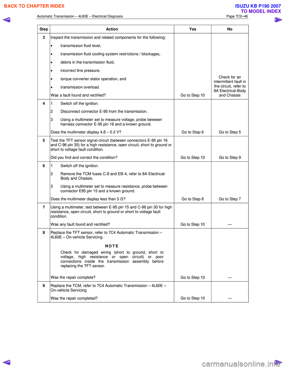
Automatic Transmission – 4L60E – Electrical Diagnosis Page 7C2–46
Step Action Yes No
3 Inspect the transmission and related components for the following:
• transmission fluid level,
• transmission fluid cooling system restrictions / blockages,
• debris in the transmission fluid,
• incorrect line pressure,
• torque converter stator operation, and
• transmission overload.
W as a fault found and rectified? Go to Step 10 Check for an
intermittent fault in
the circuit, refer to
8A Electrical-Body and Chassis
4 1 Switch off the ignition.
2 Disconnect connector E-95 from the transmission.
3 Using a multimeter set to measure voltage, probe between harness connector E-95 pin 16 and a known ground.
Does the multimeter display 4.8 – 5.2 V? Go to Step 6 Go to Step 5
5 Test the TFT sensor signal circuit (between connectors E-95 pin 16
and C-96 pin 35) for a high resistance, open circuit, short to ground or
short to voltage fault condition.
Did you find and correct the condition? Go to Step 10 Go to Step 9
6 1 Switch off the ignition.
2 Remove the TCM fuses C-8 and EB-4, refer to 8A Electrical- Body and Chassis.
3 Using a multimeter set to measure resistance, probe between connector E95 pin 15 and a known ground.
Does the multimeter display less than 5 Ω? Go to Step 8 Go to Step 7
7 Using a multimeter, test between E-95 pin 15 and C-96 pin 30 for high
resistance, open circuit, short to ground or short to voltage fault
condition.
W as any fault found and rectified? Go to Step 10 —
8 Replace the TFT sensor, refer to 7C4 Automatic Transmission –
4L60E – On-vehicle Servicing.
NOTE
Check for damaged wiring (short to ground, short to
voltage, high resistance or open circuit) or poor
connections inside the transmission assembly before
replacing the TFT sensor.
Was the repair complete? Go to Step 10 —
9 Replace the TCM, refer to 7C4 Automatic Transmission – 4L60E –
On-vehicle Servicing
Was the repair completed? Go to Step 10
—
BACK TO CHAPTER INDEX
TO MODEL INDEX
ISUZU KB P190 2007
Page 3860 of 6020
Automatic Transmission – 4L60E – Electrical Diagnosis Page 7C2–74
• Tech 2 can clear the DTC.
• The TCM clears the DTC from TCM history if the vehicle completes 40 warm-up cycles without a non-emission
related diagnostic fault occurring.
• The TCM cancels the DTC default actions when the ignition is off long enough to power down the TCM.
Test Description
The following numbers refer to the step numbers in the diagnostic table:
4 Checks the ability of the TCM to control the solenoid.
5 Checks for supply voltage to the 3-2 SS valve.
6 Checks the ability of the TCM and wiring to control the ground circuit.
8 Checks the resistance of the control valve body wiring harness and the 3-2 SS valve.
9 Checks if the 3-2 SS or control valve body wiring harness is shorted to the transmission housing.
13 Checks if the control valve body wiring harness is shorted to ground.
14 Checks if any of the other solenoids in the transmission are shorted to ground.
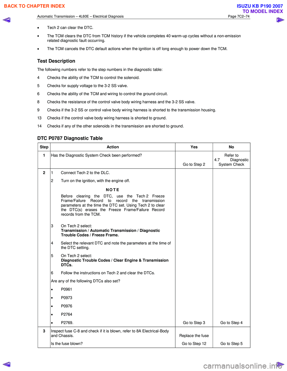
DTC P0787 Diagnostic Table
Step Action Yes No
1 Has the Diagnostic System Check been performed?
Go to Step 2 Refer to
4.7 Diagnostic System Check
2 1 Connect Tech 2 to the DLC.
2 Turn on the ignition, with the engine off.
NOTE
Before clearing the DTC, use the Tech 2 Freeze
Frame/Failure Record to record the transmission
parameters at the time the DTC set. Using Tech 2 to clear
the DTC(s) erases the Freeze Frame/Failure Record
records from the TCM.
3 On Tech 2 select: Transmission / Automatic Transmission / Diagnostic
Trouble Codes / Freeze Frame.
4 Select the relevant DTC and note the parameters at the time of the DTC setting.
5 On Tech 2 select:
Diagnostic Trouble Codes / Clear Engine & Transmission
DTCs.
6 Follow the instructions on Tech 2 and clear the DTCs.
Are any of the following DTCs also set?
• P0961
• P0973
• P0976
• P2764
• P2769. Go to Step 3 Go to Step 4
3 Inspect fuse C-8 and check if it is blown, refer to 8A Electrical-Body
and Chassis.
Is the fuse blown? Replace the fuse
Go to Step 12 Go to Step 5
BACK TO CHAPTER INDEX
TO MODEL INDEX
ISUZU KB P190 2007
Page 3877 of 6020
Automatic Transmission – 4L60E – Electrical Diagnosis Page 7C2–91
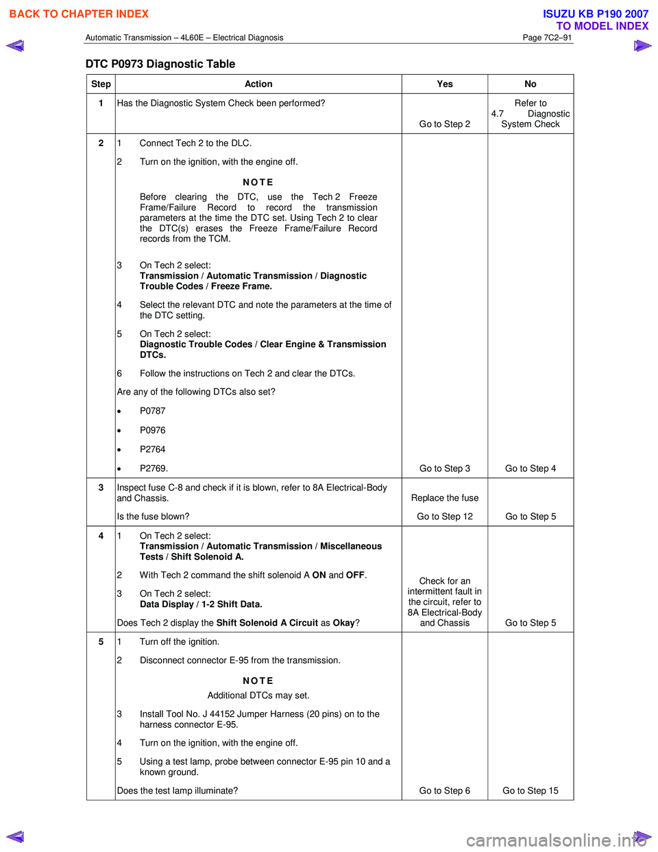
DTC P0973 Diagnostic Table
Step Action Yes No
1 Has the Diagnostic System Check been performed?
Go to Step 2 Refer to
4.7 Diagnostic System Check
2 1 Connect Tech 2 to the DLC.
2 Turn on the ignition, with the engine off.
NOTE
Before clearing the DTC, use the Tech 2 Freeze
Frame/Failure Record to record the transmission
parameters at the time the DTC set. Using Tech 2 to clear
the DTC(s) erases the Freeze Frame/Failure Record
records from the TCM.
3 On Tech 2 select: Transmission / Automatic Transmission / Diagnostic
Trouble Codes / Freeze Frame.
4 Select the relevant DTC and note the parameters at the time of the DTC setting.
5 On Tech 2 select:
Diagnostic Trouble Codes / Clear Engine & Transmission
DTCs.
6 Follow the instructions on Tech 2 and clear the DTCs.
Are any of the following DTCs also set?
• P0787
• P0976
• P2764
• P2769. Go to Step 3 Go to Step 4
3 Inspect fuse C-8 and check if it is blown, refer to 8A Electrical-Body
and Chassis.
Is the fuse blown? Replace the fuse
Go to Step 12 Go to Step 5
4 1 On Tech 2 select:
Transmission / Automatic Transmission / Miscellaneous
Tests / Shift Solenoid A.
2 With Tech 2 command the shift solenoid A ON and OFF .
3 On Tech 2 select: Data Display / 1-2 Shift Data.
Does Tech 2 display the Shift Solenoid A Circuit as Okay ? Check for an
intermittent fault in the circuit, refer to
8A Electrical-Body and Chassis Go to Step 5
5 1 Turn off the ignition.
2 Disconnect connector E-95 from the transmission.
NOTE
Additional DTCs may set.
3 Install Tool No. J 44152 Jumper Harness (20 pins) on to the harness connector E-95.
4 Turn on the ignition, with the engine off.
5 Using a test lamp, probe between connector E-95 pin 10 and a known ground.
Does the test lamp illuminate? Go to Step 6 Go to Step 15
BACK TO CHAPTER INDEX
TO MODEL INDEX
ISUZU KB P190 2007