Page 1008 of 6020

ENGINE ELECTRICAL 6D – 7
GENERATOR
REMOVAL AND INSTALLATION
Read this Section carefully before performing any removal and installation procedure. This Section gives you
important points as well as the order of operation. Be sure that you understand everything in this Section before you
begin.
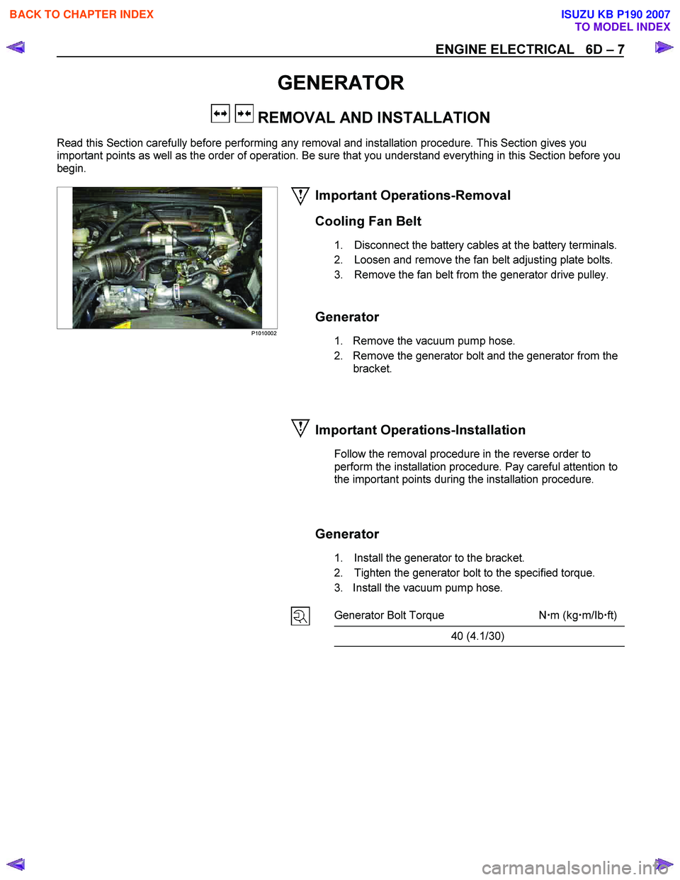
P1010002
Important Operations-Removal
Cooling Fan Belt
1. Disconnect the battery cables at the battery terminals.
2. Loosen and remove the fan belt adjusting plate bolts.
3. Remove the fan belt from the generator drive pulley.
Generator
1. Remove the vacuum pump hose.
2. Remove the generator bolt and the generator from the bracket.
Important Operations-Installation
Follow the removal procedure in the reverse order to
perform the installation procedure. Pay careful attention to
the important points during the installation procedure.
Generator
1. Install the generator to the bracket.
2. Tighten the generator bolt to the specified torque.
3. Install the vacuum pump hose.
Generator Bolt Torque N �m (kg �m/Ib �ft)
40 (4.1/30)
BACK TO CHAPTER INDEX
TO MODEL INDEX
ISUZU KB P190 2007
Page 1009 of 6020
6D – 8 ENGINE ELECTRICAL
033RY00009
Cooling Fan Drive Belt
1. Hold the generator toward the engine.
2. Install the fan belt to the three pulleys. 1 Crankshaft pulley
2 Generator pulley
3 Cooling fan drive pulley
3. Adjust the fan belt tension
Fan belt tension is adjusted by moving the generator.
Depress the drive belt mid-portion with a 98N (10
kg/22 Ib) force.
Cooling Fan Drive Belt Deflection mm (in)
New belt 4 - 7 (0.16 - 0.28)
Reuse belt 6 - 9 (0.24 - 0.35)
4. Tighten the adjusting plate bolts to the specified torque.
Adjusting Plate Bolt N·m (kg·m/lb·ft)
19 (1.9/14)
5. Reconnect the battery cable to the battery.
BACK TO CHAPTER INDEX
TO MODEL INDEX
ISUZU KB P190 2007
Page 1020 of 6020
ENGINE ELECTRICAL 6D – 19
RTW46DSH000401
Important Operations
2. Rear rotor bearing
• Re-use improper parts.
5. Rectifier
6. Stator Use a pair of long-nose plier to connect the stator coil
leads and the rectifier leads.
Finish the work as quickly as possible to prevent the
rectifier from heat transferred by the soldering.
RTW46DSH002101
3. Rotor Assembly
4. Pulley Assembly Clamp the rotor in a vise and install the pulley nut.
Pulley Nut Torque N ⋅m (kg ⋅m/lb ⋅ft)
83.3 ∼ 98.0 (8.5 ∼ 10.0 / 61 ∼ 72)
RTW46DSH006001
Remove the tape from the splines.
RTW46DSH004901
The rear ball bearing is pressed into the wheel eccentric
groove. The bearing ring projects from the groove.
During installation, rotate the bearing to the point of
minimum bearing ring projection.
Inspect the rear cover bearing box and replace it if it is
damaged.
BACK TO CHAPTER INDEX
TO MODEL INDEX
ISUZU KB P190 2007
Page 1022 of 6020

ENGINE ELECTRICAL 6D – 21
RTW06DSH000201
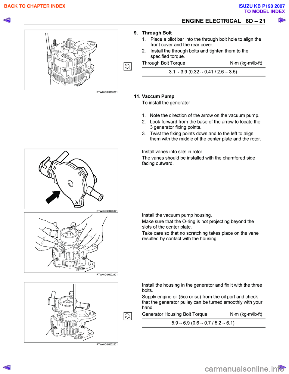
9. Through Bolt
1. Place a pilot bar into the through bolt hole to align the front cover and the rear cover.
2. Install the through bolts and tighten them to the specified torque.
Through Bolt Torque N ⋅m (kg ⋅m/lb ⋅ft)
3.1 ∼ 3.9 (0.32 ∼ 0.41 / 2.6 ∼ 3.5)
11. Vaccum Pump To install the generator -
1. Note the direction of the arrow on the vacuum pump.
2. Look forward from the base of the arrow to locate the 3 generator fixing points.
3. Twist the fixing points down and to the left to align them with the middle of the center plate and the rotor.
RTW46DSH006101
Install vanes into slits in rotor.
The vanes should be installed with the chamfered side
facing outward.
RTW46DSH002401
Install the vacuum pump housing.
Make sure that the O-ring is not projecting beyond the
slots of the center plate.
Take care so that no scratching takes place on the vane
resulted by contact with the housing.
RTW46DSH002501
Install the housing in the generator and fix it with the three
bolts.
Supply engine oil (5cc or so) from the oil port and check
that the generator pulley can be turned smoothly with your
hand.
Generator Housing Bolt Torque N ⋅m (kg ⋅m/lb ⋅ft)
5.9 ∼ 6.9 (0.6 ∼ 0.7 / 5.2 ∼ 6.1)
BACK TO CHAPTER INDEX
TO MODEL INDEX
ISUZU KB P190 2007
Page 1023 of 6020

6D – 22 ENGINE ELECTRICAL
STARTER MOTOR
REMOVAL AND INSTALLATION
Read this Section carefully before performing any removal and installation procedure. This Section gives you
important points as well as the order of operation. Be sure that you understand everything in this Section before you
begin.
Important Operations - Removal
Starter Motor
1. Disconnect the battery cable and the ground cable at the battery terminals.
2. Disconnect the magnetic switch cable at the terminal bolts.
3. Disconnect the battery cable at the starter motor and the ground cable at the cylinder body.
4. Remove the starter motor from the engine.
Important Operations – Installation
Follow the removal procedure in the reverse order to
perform the installation procedure. Pay careful attention to
the important points during the installation procedure.
Starter Motor
1. Install the starter motor to the rear plate.
2. Tighten the starter motor bolts to the specified torque.
Starter Motor Bolt Torque N⋅m (kg ⋅m/lb ⋅ft)
85 (8.7/63)
3. Reconnect the battery cable at the starter motor and
the ground cable at the cylinder body.
4. Reconnect the battery cable and the ground cable at the battery terminals.
BACK TO CHAPTER INDEX
TO MODEL INDEX
ISUZU KB P190 2007
Page 1031 of 6020
6D – 30 ENGINE ELECTRICAL
RTW46DSH005601
Important Operations
1. Magnetic Switch Assembly
1. Attach the torsion spring to the hole in the magnetic switch as illustrated.
2. Insert the shift lever into the plunger hole of the magnetic switch.
RTW46DSH005701
7. Gear Case
3,8. Dust Cover 1. Install the magnetic switch assembly in the gear case.
2. Install the dust cover.
Dust Cover Bolt Torque N⋅m (kg ⋅m/lb ⋅ft)
8 (0.8/5.4)
10. Pinion Assembly
Apply a coat of grease to the reduction gear and install the
pinion assembly to the armature shaft.
065RY00041
RTW46DSH004501
21. Brush Holders
1. Install the brushes into the brush holder with raising the spring end of the brush spring.
Take care not to damage the commutator face.
2. Install the brush holder with aligning the peripheries of the yoke and the brush holder.
BACK TO CHAPTER INDEX
TO MODEL INDEX
ISUZU KB P190 2007
Page 1032 of 6020
ENGINE ELECTRICAL 6D – 31
24. Through Bolt
Install the through bolts in the rear cover and tighten them
to the specified torque.
Through Bolt Torque N⋅m (kg ⋅m/lb ⋅ft)
8.1 (0.83/6.00)
065RY00044
RTW46DSH002601
25. Lead Wire
Connect the lead wire in the magnetic switch and tighten
the terminal nut to the specified torque.
Lead Wire Terminal Nut Torque N ⋅m (kg ⋅m/lb ⋅ft)
8.6 (0.88/6.40)
RTW46DSH005801
Inspection After Assembly
Use a vernier caliper to measure the pinion shaft thrust
play.
The pinion shaft thrust play is equal to the pinion shaft end
and pinion stopper clearance.
Pinion Shaft Thrust Play mm (in)
0.1 – 2.0 (0.004 – 0.078)
BACK TO CHAPTER INDEX
TO MODEL INDEX
ISUZU KB P190 2007
Page 1290 of 6020

6E-256 Engine Control System (4JH1)
Important:
The following symptom tables contain groups o
f
possible causes for each symptom. The order of these
procedures is not important. If the scan tool readings do
not indicate the problems, then proceed in a logical
order, easiest to check or most likely to cause first. In
order to determine if a specific vehicle is using a
particular system or component, refer to Engine
Controls Schematics for an application.
Use the following tables when diagnosing a symptom
complaint:
• Intermittent Conditions
• Hard Start
• Rough, Unstable, or Incorrect Idle and Stalling
• Cuts Out, Misses
• Surge/Chuggles
• Lack of Power, Sluggishness, or Sponginess
• Hesitation, Sag, Stumble
• Fuel Knock/Combustion Noise
• Poor Fuel Economy
• Excessive Smoke (Black Smoke)
• Excessive Smoke (W hite Smoke)
Intermittent Conditions
Checks Action
DEFINITION:The problem is not currently present but is indicated in DTC History.
OR
There is a customer complaint, but the symptom cannot currently be duplicated, if the problem is not DTC related.
Preliminary Checks • Refer to Symptoms – Engine Controls before starting.
Harness/Connector Many intermittent open or shorted circuits are affected by harness/connector
movement that is caused by vibration, engine torque, bumps/rough pavement, etc.
Test for this type of condition by performing the applicable procedure from the
following list:
• Move related connectors and wiring while monitoring the appropriate scan tool data.
• Move related connectors and wiring with the component commanded ON, and OFF,
with the scan tool. Observe the component operation.
• W ith the engine running, move related connectors and wiring while monitoring
engine operation.
If harness or connector movement affects the data displayed, component/system
operation, or engine operation, inspect and repair the harness/connections as
necessary.
Refer to Electrical Connections or W iring.
BACK TO CHAPTER INDEX
TO MODEL INDEX
ISUZU KB P190 2007