Page 980 of 6020

6C – 16 FUEL SYSTEM
FILLER NECK
Removal
1. Remove the fuel tank.
NOTE: Refer to "Fuel Tank" in this section.
2. Put a marking the following point as the filler neck assembl
y
is restored.
• Each joint area of the hose (to restore axial direction and
insertion length of the hose)
• Each fasten area of the clamp (to restore axial direction
and position of the clamp)
• Each bolt in the clamp (to restore fasten length of bolt in
the clamp)
• The band clip (to restore position and fasten length o
f
the band clip)
NOTE: Cover end of each hose and pipe to prevent any dust
entering.
Installation
1. Align each marking and restore the following point.
• Each joint area of the hose (Restore axial direction and
insertion length of the hose)
• Each fasten area of the clamp (Restore axial direction
and position of the clamp)
• Each bolt in the clamp (Restore fasten length of bolt in
the clamp)
Torque N·m (kg·m / lb ft)
2.5 (0.25 / 21.7)
filler neck side except flat deck model.
• The band clip (Restore position and fasten length of the
band clip)
2. Install the fuel tank.
NOTE: Refer to "Fuel Tank" in this section.
BACK TO CHAPTER INDEX
TO MODEL INDEX
ISUZU KB P190 2007
Page 985 of 6020
FUEL SYSTEM 6C – 21
RTW 46CSH000201
Installation
1. Injection Pump
1) Install the injection pump gear (W hen gear is removed).
Injection Pump Gear Nut N⋅m (kg ⋅m/lb ft)
64 (6.5 / 47)
2) Bring the piston in the No.1 cylinder to TDC on the
compression stroke by turning the crankshaft until the
crankshaft pulley TDC line aligned with the timing
mark.
020L200017
3) Install the injection pump to the timing gear case with
align the timing mark on the pump gear to the arrow
mark on the timing gear case cover.
4) Check that the setting marks of the injection pump gear and the idler gear B are aligned.
5) Remove the lock bolt (M6 × 30) from the idle gear “B”.
6C-7
6) Tighten the injection pump fixing bolts to the specified
torque.
Injection Pump Bolts Torque N·m (kg·m/lb ft)
19 (1.9 / 14)
BACK TO CHAPTER INDEX
TO MODEL INDEX
ISUZU KB P190 2007
Page 986 of 6020

RTW 46CSH000101
4JA1TC/4JH1TC
RTW 36AMH000101
2. Injection Pump Bracket
1) Install the injection")
6C – 22 FUEL SYSTEM
4JA1T (L)
RTW 46CSH000101
4JA1TC/4JH1TC
RTW 36AMH000101
2. Injection Pump Bracket
1) Install the injection pump bracket (6) and the bracket bolts (7) and (8) to the cylinder body. Temporarily
tighten the bracket bolts.
2) Tighten the bracket bolts (7) to the specified torque.
3) Tighten the bracket bolts (8) to the specified torque.
Note:
Tighten the bracket bolt (8) first.
Injection Pump Bracket Torque N·m(kg·m / lb ft)
(8) 19 (1.9 / 14)
(7) 40 (4.1 / 30)
3. Timing Check Hole Cover
Install the timing check hole cover and tighten bolts to the
specified torque.
Timing Check Hole Cover Bolts
Torque N·m(kg·m / lb ft)
8 (0.8 / 69)
4. Injection Pump Cover (4JA1TC/4JH1TC only)
5. Intake Manifold
1) Install the intake manifold with gasket.
Intake Manifold Bolts
Torque N·m(kg·m / lb ft)
19 (1.9 / 14)
Intake Manifold Nuts Torque N·m(kg·m / lb ft)
24 (2.4 / 17)
2) Install the EGR valve to the intake manifold and EGR pipe temporarily.
3) Tighten the nuts and bolts to the specified torque
Torque N ⋅m (kg ⋅m/lb ft)
Nuts 24 (2.4/17)
Bolts 27 (2.8/20)
BACK TO CHAPTER INDEX
TO MODEL INDEX
ISUZU KB P190 2007
Page 987 of 6020

29 (3.0 / 22)
Nozzle Side (4JA1TC/4JH1TC) N·m(kg·m / lb ft)
29 (3")
FUEL SYSTEM 6C – 23
6. Injection Pipe
Install the injection pipe.
Injection Pipe Torque N·m(kg·m / lb ft)
29 (3.0 / 22)
Nozzle Side (4JA1TC/4JH1TC) N·m(kg·m / lb ft)
29 (3.0 / 22)
Pump Side (4JA1TC/4JH1TC) N·m(kg·m / lb ft)
40 (4.1 / 30)
7. Injection Pipe Clip Install the injection pipe clip.
Note:
Make absolutely sure that the clip is correctly
positioned.
Injection Pipe Clip Torque N·m(kg·m / lb in)
8 (0.8 / 69)
8. Leak Off Pipe and Leak Off Hose
Install the leak off pipe to injection nozzle and connect the
leak off hose to the injection pump.
9. Fuel Filter Bracket (Except EURO III model)
Install the fuel filter bracket and tighten bolts to the
specified torque.
Fuel Filter Bracket Bolts Torque N·m(kg·m / lb ft)
21 (2.1 / 15)
10. Fuel Filter Assembly (Except EURO III model) Install the fuel filter assembly to bracket and tighten bolts
to the specified torque.
Fuel Filter Assembly Bolts
Torque N·m(kg·m / lb ft)
21 (2.1 / 15)
11. Fuel Pipe
1) Connect the fuel hoses to the fuel filter or priming pump.
2) Connect the fuel hoses to the injection pump.
12. Oil Level Gauge Install the oil level gauge and tighten bolts to the specified
torque.
Oil Level Gauge Bolts
Torque N·m(kg·m / lb ft)
M8: 19 (1.9 / 14)
M6: 8 (0.8/6 lb in)
BACK TO CHAPTER INDEX
TO MODEL INDEX
ISUZU KB P190 2007
Page 993 of 6020
FUEL SYSTEM 6C – 29
5. Install the pins in the spacer.
6. Install the nozzle on the spacer.
7. Hand-tighten the adjustment retaining nut together with the gasket to the nozzle holder.
Retaining nut: 157892-3200 (Bosch AS)
Gasket: 157892-5100 (Bosch AS) (Bosch AS = Bosch Automotive Systems Corporation)
8. Tighten the adjustment retaining nut to the specified torque.
Torque: 5.1 kg·m (36.9 Ib·ft/50 N·m)
9. Set the nozzle holder to the nozzle tester.
10. Operate the nozzle tester and measure the first nozzle opening pressure.
11. If the first nozzle opening pressure is not as specified, disassemble the nozzle holder and replace the shim
until the pressure is as specified.
CAUTION:
• Use a micrometer to measure shim thickness.
040MV019.tif
040MV010.tif
040MV014-1.tif
040MV030.tif
BACK TO CHAPTER INDEX
TO MODEL INDEX
ISUZU KB P190 2007
Page 999 of 6020

FUEL SYSTEM 6C – 35
Second nozzle opening pressure adjustment
If the second nozzle opening pressure is not as specified,
disassemble the nozzle from the nozzle holder and
replace the shim until the pressure is as specified.
CAUTION:
• Because the second opening pressure changes
when the first opening pressure changes, the
second opening pressure must be adjusted when
the first opening pressure changes.
• Use a micrometer to measure shim thickness.
• Use some combination of 3 adjusting shims to
adjust the pressure.
• Second nozzle opening pressure adjusting shims
Part No. (ISUZU) Thickness
(mm) Part No.
(ISUZU) Thickness
(mm)
897116-0290 0.10 897116-0380 0.53
897116-0320 0.20 897116-0390 0.54
897116-0330 0.30 897116-0400 0.55
897116-0340 0.40 897116-0410 0.56
897116-0350 0.50 897116-0420 0.57
897116-0360 0.51 897116-0430 0.58
897116-0370 0.52 897116-0440 0.59
Final inspection
1. Remove the dial gauge, nut and dial gauge holder.
2. Remove the adjustment retaining nut and gasket.
3. Install the original retaining nut, confirm that the pins are inserted fully into the nozzle, and then hand-tighten
the retaining nut. Then, tighten the original retaining
nut to the specified torque.
Torque: 7.0 kg·m (50.6 Ib·ft/69 N·m)
040MV017.tif
040LX009.tif
040MV028.tif
040MV014-1.ti
f
BACK TO CHAPTER INDEX
TO MODEL INDEX
ISUZU KB P190 2007
Page 1002 of 6020

SECTION 6D
ENGINE ELECTRICAL
TABLE OF CONTENTS
PAGE
Main Data and Specifications ......................................................................................... 6D - 2
General Description ........................................................................................................ 6D - 3
Torque Specifications ..................................................................................................... 6D - 5
Generator ...................................................................................................................... ... 6D - 7
Removal and Installation ............................................................................................ 6D - 7
Disassembly ................................................................................................................ 6D - 9
Inspection and Repair ................................................................................................. 6D - 12
Reassembly ................................................................................................................. 6D - 18
Starter Motor .................................................................................................................. .. 6D - 22
Removal and Installation ............................................................................................ 6D - 22
Disassembly ................................................................................................................ 6D - 23
Inspection and Repair ................................................................................................. 6D - 26
Reassembly ................................................................................................................. 6D - 29
Pre-heating System ......................................................................................................... 6D -33
Inspection and Repair ................................................................................................. 6D -33
Glow Relay ................................................................................................................... 6D -33
Glow Plug..................................................................................................................... 6D -33
EGR System ................................................................................................................. 6D -33
ENGINE ELECTRICAL 6D – 1
BACK TO CHAPTER INDEX
TO MODEL INDEX
ISUZU KB P190 2007
Page 1006 of 6020
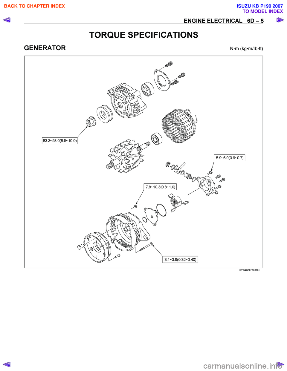
ENGINE ELECTRICAL 6D – 5
TORQUE SPECIFICATIONS
GENERATOR N �m (kg �m/Ib �ft)
RTW46DLF000201
BACK TO CHAPTER INDEX
TO MODEL INDEX
ISUZU KB P190 2007
 Install the injection pump gear (W hen gear is removed).
Injection Pump Gear Nut N⋅m (kg ⋅m/lb ft)
64 (6")