2007 ISUZU KB P190 coolant temperature
[x] Cancel search: coolant temperaturePage 2559 of 6020
Engine Mechanical – V6 Page 6A1–80
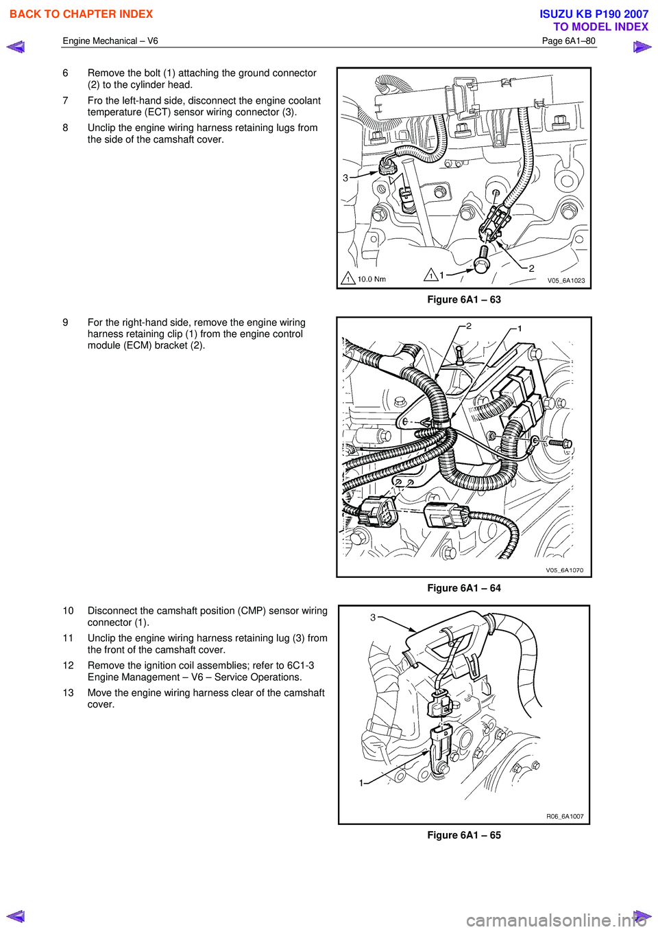
6 Remove the bolt (1) attaching the ground connector
(2) to the cylinder head.
7 Fro the left-hand side, disconnect the engine coolant temperature (ECT) sensor wiring connector (3).
8 Unclip the engine wiring harness retaining lugs from the side of the camshaft cover.
Figure 6A1 – 63
9 For the right-hand side, remove the engine wiring harness retaining clip (1) from the engine control
module (ECM) bracket (2).
Figure 6A1 – 64
10 Disconnect the camshaft position (CMP) sensor wiring connector (1).
11 Unclip the engine wiring harness retaining lug (3) from the front of the camshaft cover.
12 Remove the ignition coil assemblies; refer to 6C1-3 Engine Management – V6 – Service Operations.
13 Move the engine wiring harness clear of the camshaft cover.
Figure 6A1 – 65
BACK TO CHAPTER INDEX
TO MODEL INDEX
ISUZU KB P190 2007
Page 2641 of 6020
Engine Mechanical – V6 Page 6A1–162
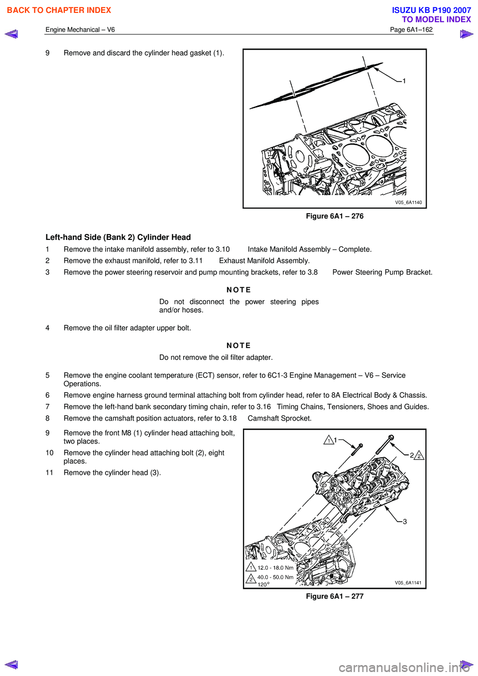
9 Remove and discard the cylinder head gasket (1).
Figure 6A1 – 276
Left-hand Side (Bank 2) Cylinder Head
1 Remove the intake manifold assembly, refer to 3.10 Intake Manifold Assembly – Complete.
2 Remove the exhaust manifold, refer to 3.11 Exhaust Manifold Assembly.
3 Remove the power steering reservoir and pump mounting brackets, refer to 3.8 Power Steering Pump Bracket.
NOTE
Do not disconnect the power steering pipes
and/or hoses.
4 Remove the oil filter adapter upper bolt. NOTE
Do not remove the oil filter adapter.
5 Remove the engine coolant temperature (ECT) sensor, refer to 6C1-3 Engine Management – V6 – Service Operations.
6 Remove engine harness ground terminal attaching bolt from cylinder head, refer to 8A Electrical Body & Chassis.
7 Remove the left-hand bank secondary timing chain, refer to 3.16 Timing Chains, Tensioners, Shoes and Guides.
8 Remove the camshaft position actuators, refer to 3.18 Camshaft Sprocket.
9 Remove the front M8 (1) cylinder head attaching bolt, two places.
10 Remove the cylinder head attaching bolt (2), eight places.
11 Remove the cylinder head (3).
Figure 6A1 – 277
BACK TO CHAPTER INDEX
TO MODEL INDEX
ISUZU KB P190 2007
Page 2677 of 6020
Engine Mechanical – V6 Page 6A1–198
k Timing chains, tensioners, shoes, guides & sprockets, refer to 3.16 Timing Chains, Tensioners, Shoes and
Guides.
l Cylinder head assemblies, refer to 3.22 Cylinder Head Assembly.
m Oil pan assembly, refer to 4.2 Oil Pan and Oil Pump Suction Pipe Assembly.
n Piston and connecting rod assemblies, refer to 4.5 Pistons, Pins, Rings, Connecting Rods and Big-end Bearings.
o Crankshaft assembly, refer to 4.6 Crankshaft and Main Bearings.
p Piston oil nozzles, refer 4.5 Pistons, Pins, Rings, Connecting Rods and Big-end Bearings.
Reassemble
Reassembly of the engine assembly is the reverse of the disassembly procedure.
Reinstall
Reinstallation of the engine assembly is the reverse to the removal procedure, noting the following:
NOTE
Refer to 6 Torque Wrench Specifications
for the correct torque specifications.
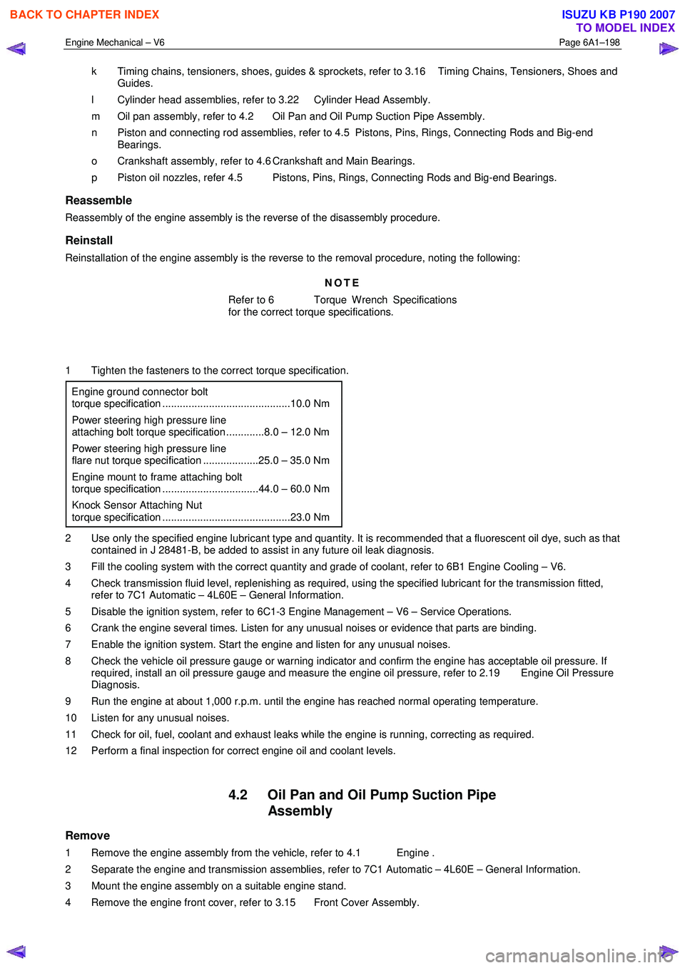
1 Tighten the fasteners to the correct torque specification.
Engine ground connector bolt
torque specification ............................................10.0 Nm
Power steering high pressure line
attaching bolt torque specification .............8.0 – 12.0 Nm
Power steering high pressure line
flare nut torque specification ...................25.0 – 35.0 Nm
Engine mount to frame attaching bolt
torque specification .................................44.0 – 60.0 Nm
Knock Sensor Attaching Nut
torque specification ............................................23.0 Nm
2 Use only the specified engine lubricant type and quantity. It is recommended that a fluorescent oil dye, such as that contained in J 28481-B, be added to assist in any future oil leak diagnosis.
3 Fill the cooling system with the correct quantity and grade of coolant, refer to 6B1 Engine Cooling – V6.
4 Check transmission fluid level, replenishing as required, using the specified lubricant for the transmission fitted, refer to 7C1 Automatic – 4L60E – General Information.
5 Disable the ignition system, refer to 6C1-3 Engine Management – V6 – Service Operations.
6 Crank the engine several times. Listen for any unusual noises or evidence that parts are binding.
7 Enable the ignition system. Start the engine and listen for any unusual noises.
8 Check the vehicle oil pressure gauge or warning indicator and confirm the engine has acceptable oil pressure. If required, install an oil pressure gauge and measure the engine oil pressure, refer to 2.19 Engine Oil Pressure
Diagnosis.
9 Run the engine at about 1,000 r.p.m. until the engine has reached normal operating temperature.
10 Listen for any unusual noises.
11 Check for oil, fuel, coolant and exhaust leaks while the engine is running, correcting as required.
12 Perform a final inspection for correct engine oil and coolant levels.
4.2 Oil Pan and Oil Pump Suction Pipe Assembly
Remove
1 Remove the engine assembly from the vehicle, refer to 4.1 Engine .
2 Separate the engine and transmission assemblies, refer to 7C1 Automatic – 4L60E – General Information.
3 Mount the engine assembly on a suitable engine stand.
4 Remove the engine front cover, refer to 3.15 Front Cover Assembly.
BACK TO CHAPTER INDEX
TO MODEL INDEX
ISUZU KB P190 2007
Page 2792 of 6020
Engine Mechanical – V6 Page 6A1–15
Page 6A1–15
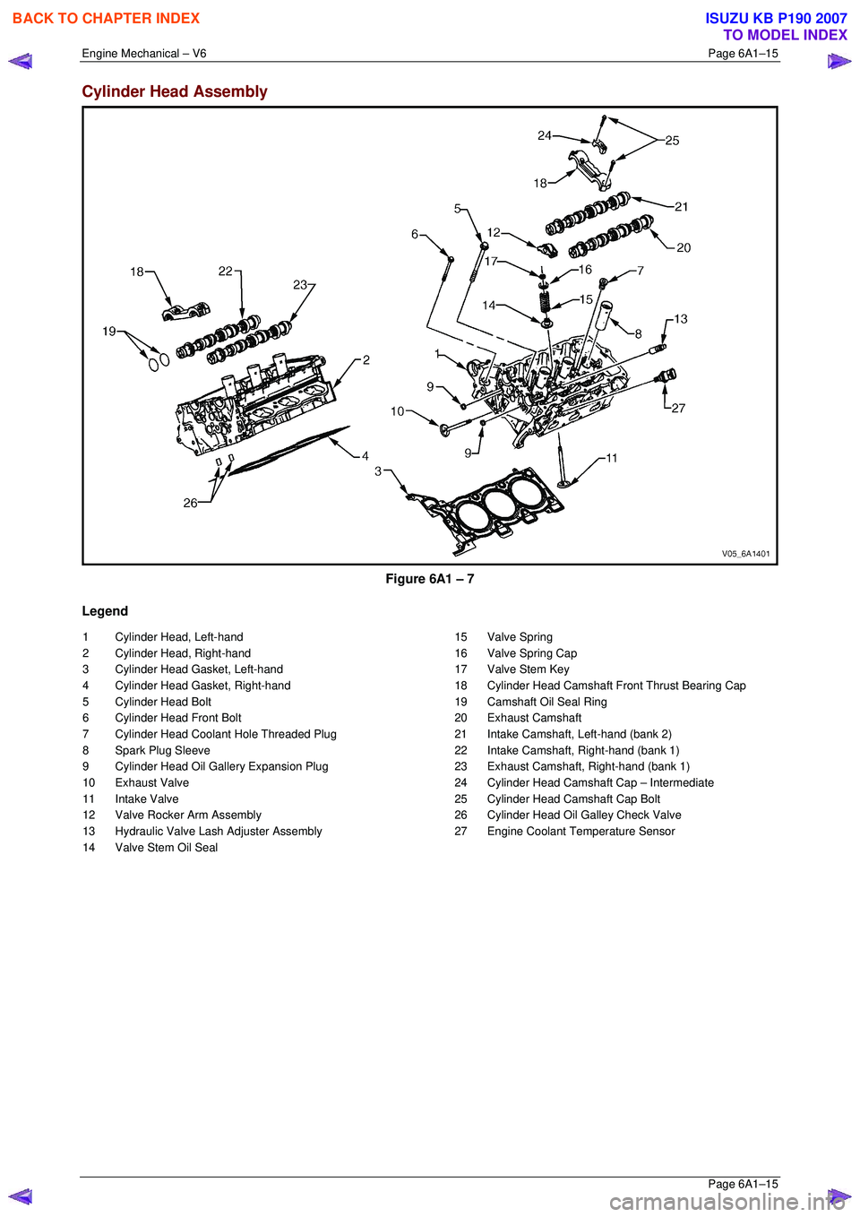
Cylinder Head Assembly
Figure 6A1 – 7
Legend
1 Cylinder Head, Left-hand
2 Cylinder Head, Right-hand
3 Cylinder Head Gasket, Left-hand
4 Cylinder Head Gasket, Right-hand
5 Cylinder Head Bolt
6 Cylinder Head Front Bolt
7 Cylinder Head Coolant Hole Threaded Plug
8 Spark Plug Sleeve
9 Cylinder Head Oil Gallery Expansion Plug
10 Exhaust Valve
11 Intake Valve
12 Valve Rocker Arm Assembly
13 Hydraulic Valve Lash Adjuster Assembly
14 Valve Stem Oil Seal 15 Valve Spring
16 Valve Spring Cap
17 Valve Stem Key
18 Cylinder Head Camshaft Front Thrust Bearing Cap
19 Camshaft Oil Seal Ring
20 Exhaust Camshaft
21 Intake Camshaft, Left-hand (bank 2)
22 Intake Camshaft, Right-hand (bank 1)
23 Exhaust Camshaft, Right-hand (bank 1)
24 Cylinder Head Camshaft Cap – Intermediate
25 Cylinder Head Camshaft Cap Bolt
26 Cylinder Head Oil Galley Check Valve
27 Engine Coolant Temperature Sensor
BACK TO CHAPTER INDEX
TO MODEL INDEX
ISUZU KB P190 2007
Page 2820 of 6020
Engine Mechanical – V6 Page 6A1–43
Page 6A1–43
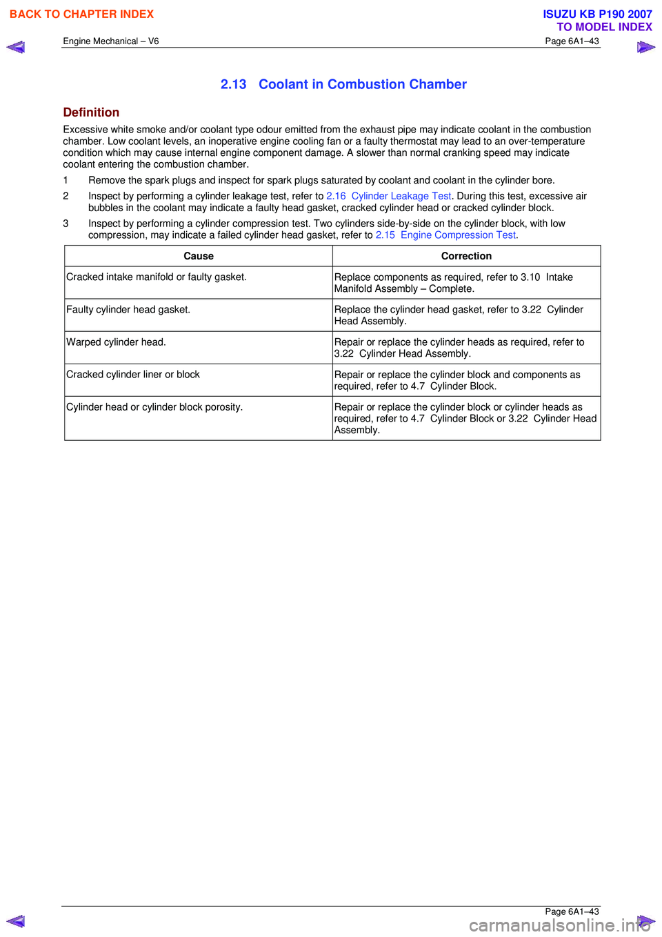
2.13 Coolant in Combustion Chamber
Definition
Excessive white smoke and/or coolant type odour emitted from the exhaust pipe may indicate coolant in the combustion
chamber. Low coolant levels, an inoperativ e engine cooling fan or a faulty thermostat may lead to an over-temperature
condition which may cause internal engine component damage. A slower than normal cranking speed may indicate
coolant entering the combustion chamber.
1 Remove the spark plugs and inspect for spark plugs sa turated by coolant and coolant in the cylinder bore.
2 Inspect by performing a cylinder leakage test, refer to 2.16 Cylinder Leakage Test. During this test, excessive air
bubbles in the coolant may indicate a faulty head ga sket, cracked cylinder head or cracked cylinder block.
3 Inspect by performing a cylinder compression test. Two cylinders side-by-side on the cylinder block, with low
compression, may indicate a fa iled cylinder head gasket, refer to 2.15 Engine Compression Test.
Cause Correction
Cracked intake manifold or faulty gasket. Replace components as required, refer to 3.10 Intake
Manifold Assembly – Complete.
Faulty cylinder head gasket. Replace the cylinder head gasket, refer to 3.22 Cylinder
Head Assembly.
Warped cylinder head. Repair or replace the cylinder heads as required, refer to
3.22 Cylinder Head Assembly.
Cracked cylinder liner or block Repair or replace the cylinder block and components as
required, refer to 4.7 Cylinder Block.
Cylinder head or cylinder block porosity. Repair or replace the cylinder block or cylinder heads as
required, refer to 4.7 Cylinder Block or 3.22 Cylinder Head
Assembly.
BACK TO CHAPTER INDEX
TO MODEL INDEX
ISUZU KB P190 2007
Page 2821 of 6020
Engine Mechanical – V6 Page 6A1–44
Page 6A1–44
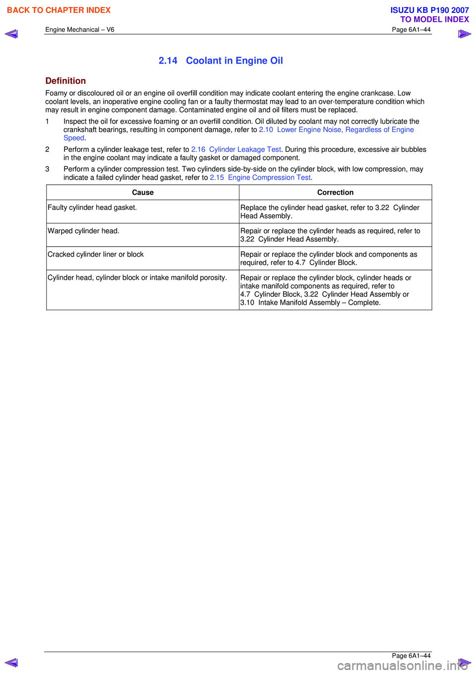
2.14 Coolant in Engine Oil
Definition
Foamy or discoloured oil or an engine oil overfill condition may indicate coolant entering the engine crankcase. Low
coolant levels, an inoperative engine cooli ng fan or a faulty thermostat may lead to an over-temperature condition which
may result in engine component damage. Contaminat ed engine oil and oil filters must be replaced.
1 Inspect the oil for excessive foaming or an overfill condition. Oil diluted by coolant may not correctly lubricate the
crankshaft bearings, resulting in component damage, refer to 2.10 Lower Engine Noise, Regardless of Engine
Speed .
2 Perform a cylinder leakage test, refer to 2.16 Cylinder Leakage Test. During this procedure, excessive air bubbles
in the engine coolant may indicate a faulty gasket or damaged component.
3 Perform a cylinder compression test. Two cylinders side-by -side on the cylinder block, with low compression, may
indicate a failed cylinder head gasket, refer to 2.15 Engine Compression Test.
Cause Correction
Faulty cylinder head gasket. Replace the cylinder head gasket, refer to 3.22 Cylinder
Head Assembly.
Warped cylinder head. Repair or replace the cylinder heads as required, refer to
3.22 Cylinder Head Assembly.
Cracked cylinder liner or block Repair or replace the cylinder block and components as
required, refer to 4.7 Cylinder Block.
Cylinder head, cylinder block or intake manifold porosity. Repair or replace the cylinder block, cylinder heads or
intake manifold components as required, refer to
4.7 Cylinder Block, 3.22 Cylinder Head Assembly or
3.10 Intake Manifold Assembly – Complete.
BACK TO CHAPTER INDEX
TO MODEL INDEX
ISUZU KB P190 2007
Page 2830 of 6020
Engine Mechanical – V6 Page 6A1–53
Page 6A1–53
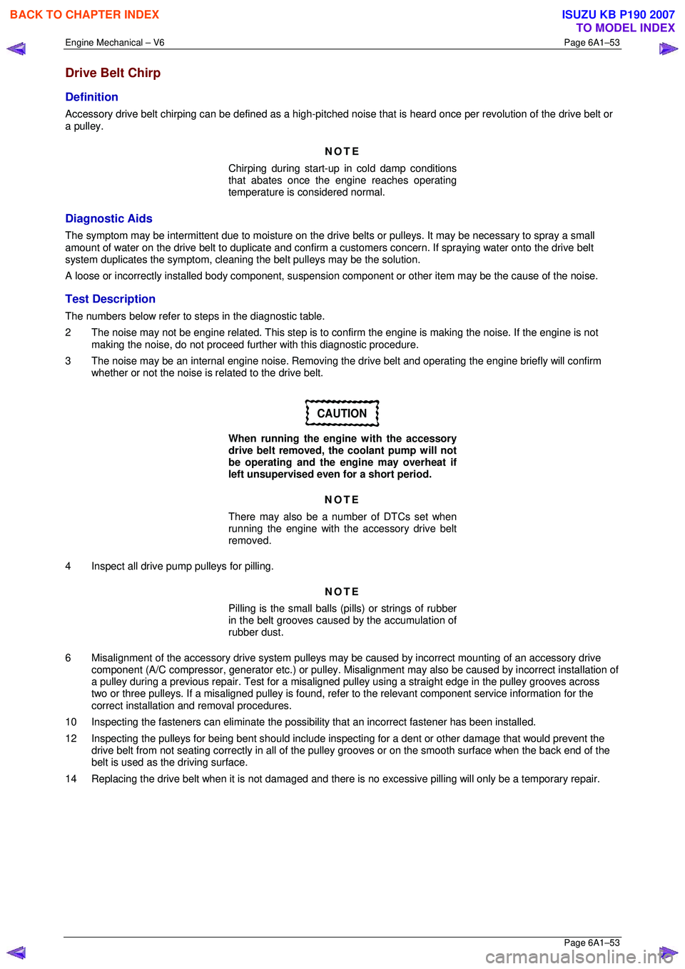
Drive Belt Chirp
Definition
Accessory drive belt chirping can be defined as a high-pitched noise that is heard once per revolution of the drive belt or
a pulley.
NOTE
Chirping during start-up in cold damp conditions
that abates once the engine reaches operating
temperature is considered normal.
Diagnostic Aids
The symptom may be intermittent due to moisture on the driv e belts or pulleys. It may be necessary to spray a small
amount of water on the drive belt to dup licate and confirm a customers concern. If spraying water onto the drive belt
system duplicates the symptom, cleaning the belt pulleys may be the solution.
A loose or incorrectly installed body component, suspension component or other item may be the cause of the noise.
Test Description
The numbers below refer to steps in the diagnostic table.
2 The noise may not be engine related. This step is to confirm the engine is making t he noise. If the engine is not
making the noise, do not proceed further with this diagnostic procedure.
3 The noise may be an internal engine noise. Removing the drive belt and operating the engine briefly will confirm
whether or not the noise is related to the drive belt.
CAUTION
When running the engine with the accessory
drive belt removed, the coolant pump will not
be operating and the engine may overheat if
left unsupervised even for a short period.
NOTE
There may also be a number of DTCs set when
running the engine with the accessory drive belt
removed.
4 Inspect all drive pump pulleys for pilling. NOTE
Pilling is the small balls (p ills) or strings of rubber
in the belt grooves caused by the accumulation of
rubber dust.
6 Misalignment of the accessory drive system pulleys ma y be caused by incorrect mounting of an accessory drive
component (A/C compressor, generator etc.) or pulley. Misa lignment may also be caused by incorrect installation of
a pulley during a previous repair. Test for a misaligned pulley using a straight edge in the pulley grooves across
two or three pulleys. If a misaligned pulley is found, refer to the relevant component service information for the
correct installation and removal procedures.
10 Inspecting the fasteners can elim inate the possibility that an incorrect fastener has been installed.
12 Inspecting the pulleys for being bent should include inspec ting for a dent or other damage that would prevent the
drive belt from not seating correctly in all of the pulley grooves or on the smooth surface when the back end of the
belt is used as the driving surface.
14 Replacing the drive belt when it is not damaged and there is no excessive p illing will only be a temporary repair.
BACK TO CHAPTER INDEX
TO MODEL INDEX
ISUZU KB P190 2007
Page 2872 of 6020
Engine Mechanical – V6 Page 6A1–95
Page 6A1–95
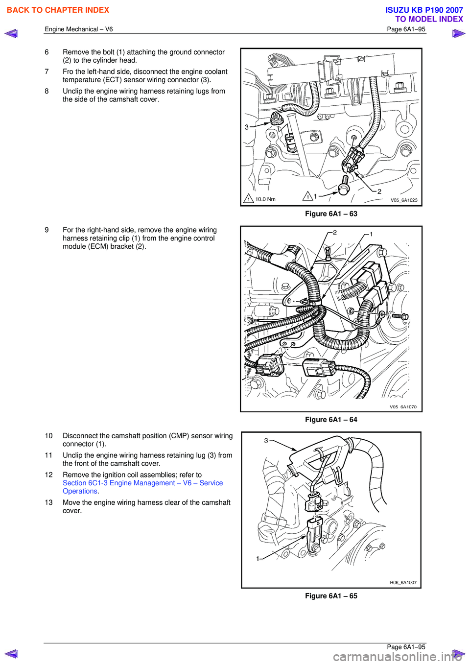
6 Remove the bolt (1) attaching the ground connector
(2) to the cylinder head.
7 Fro the left-hand side, disconnect the engine coolant temperature (ECT) sensor wiring connector (3).
8 Unclip the engine wiring harness retaining lugs from the side of the camshaft cover.
Figure 6A1 – 63
9 For the right-hand side, remove the engine wiring harness retaining clip (1) from the engine control
module (ECM) bracket (2).
Figure 6A1 – 64
10 Disconnect the camshaft position (CMP) sensor wiring connector (1).
11 Unclip the engine wiring harness retaining lug (3) from the front of the camshaft cover.
12 Remove the ignition coil assemblies; refer to Section 6C1-3 Engine Management – V6 – Service
Operations .
13 Move the engine wiring harness clear of the camshaft cover.
Figure 6A1 – 65
BACK TO CHAPTER INDEX
TO MODEL INDEX
ISUZU KB P190 2007