2007 ISUZU KB P190 coolant temperature
[x] Cancel search: coolant temperaturePage 3030 of 6020
Engine Mechanical – V6 Page 6A1–253
Page 6A1–253
k Timing chains, tensioners, shoes, guides & sprockets, refer to 3.16 Timing Chains, Tensioners, Shoes and
Guides .
l Cylinder head assemblies, refer to 3.22 Cylinder Head Assembly.
m Oil pan assembly, refer to 4.2 Oil Pan and Oil Pump Suction Pipe Assembly .
n Piston and connecting rod assemblies, refer to 4.5 Pistons, Pins, Rings, Connecting Rods and Big-end
Bearings .
o Crankshaft assembly, refer to 4.6 Crankshaft and Main Bearings.
p Piston oil nozzles, refer 4.5 Pistons, Pins, Rings, Connecting Rods and Big-end Bearings .
Reassemble
Reassembly of the engine assembly is the reverse of the disassembly procedure.
Reinstall
Reinstallation of the engine assembly is the revers e to the removal procedure, noting the following:
NOTE
Refer to 6 Torque Wrench Specifications for the
correct torque specifications.
1 Tighten the fasteners to the co rrect torque specification.
Engine ground connector bolt
torque specificat ion ............................................ 10.0 Nm
Power steering high pressure line
attaching bolt torque specification ............. 8.0 – 12.0 Nm
Power steering high pressure line
flare nut torque specif ication ................... 25. 0 – 35.0 Nm
Engine mount to frame attaching bolt
torque specification ................................. 44. 0 – 60.0 Nm
Knock Sensor Attaching Nut
torque specification ............................................ 23.0 Nm
2 Use only the specified engine lubricant type and quantity. It is recommended that a fluorescent oil dye, such as that
contained in J 28481-B, be added to assist in any future oil leak diagnosis.
3 Fill the cooling system with the corre ct quantity and grade of coolant, refer to Section 6B1 Engine Cooling – V6.
4 Check transmission fluid level, replenishing as required, using the specified lubricant for the transmission fitted,
refer to Section 7C1 Automatic – 4L60E – General Information .
5 Disable the ignition system, refer to Section 6C1-3 Engine Management – V6 – Service Operations.
6 Crank the engine several times. Listen for any unusual noises or evidence that parts are binding.
7 Enable the ignition system. Start t he engine and listen for any unusual noises.
8 Check the vehicle oil pressure gauge or warning indica tor and confirm the engine has acceptable oil pressure. If
required, install an oil pressure gauge and m easure the engine oil pressure, refer to 2.19 Engine Oil Pressure
Diagnosis .
9 Run the engine at about 1,000 r. p.m. until the engine has reached normal operating temperature.
10 Listen for any unusual noises.
11 Check for oil, fuel, coolant and exhaust leaks wh ile the engine is running, correcting as required.
12 Perform a final inspection for correct engine oil and coolant levels.
BACK TO CHAPTER INDEX
TO MODEL INDEX
ISUZU KB P190 2007
Page 3136 of 6020
Engine Cooling – V6 Engine Page 6B1–1
Section 6B1
Engine Cooling – V6
ATTENTION
Before performing any Service Operation or other procedure described in this Section, refer to 1.1 WARNING,
CAUTION and NOTES for correct workshop practices with regard to safety and/or property damage.
1 General Information ............................................................................................................ ...................3
1.1 WARNING, CAUTION and NOTES ..................................................................................................... ................... 4
1.2 Definition of WARNING, CAUTION and NOTE Statements ......................................................................... .. 4
WARNING defined ............................................................................................................................................. 4
CAUTION defined .............................................................................................................................................. 4
NOTE defined..................................................................................................................................................... 4
2 General Description ............................................................................................................ ...................5
2.1 Radiator Assembly .............................................................................................................. .................................. 5
2.2 Cooling Fan – Standard Specification.................................................................................................................. 7
Overview ................................................................................................................................................................. 7
Cooling Fan and Shroud Assembly ................................................................................................ .................... 8
Fan Motor ........................................................................................................................................................... 8
Fan Operation .................................................................................................................. .................................. 8
V6 Cooling Fan Wiring Diagram .................................................................................................. ....................... 9
Fan Assembly connector .................................................................................................................................. 10
2.3 Coolant Pump....................................................................................................................................................... 10
2.4 Coolant Outlet Housing ......................................................................................................... .............................. 11
2.5 Thermostat ........................................................................................................................................................... 11
2.6 Coolant Filler Cap ............................................................................................................. ................................... 13
2.7 Coolant Recovery Reservoir ..................................................................................................... .......................... 14
2.8 Engine Coolant Temperature Sensor .............................................................................................. ................... 15
3 Service Operations ...............................................................................................................................16
3.1 Service Notes ....................................................................................................................................................... 16
Safety .................................................................................................................................................................... 16
Periodic Servicing............................................................................................................. ................................... 16
Environmental Issues ........................................................................................................... ............................... 16
3.2 Coolant Maintenance ........................................................................................................................................... 17
Topping Up the Cooling System.................................................................................................. ....................... 18
Testing Coolant Concentration........................................................................................................................... 18
Method 1 – Refractometer................................................................................................................................ 18
Method 2 – Hydrometer.................................................................................................................................... 21
3.3 Draining and Filling Cooling System ............................................................................................ ..................... 22
Draining ................................................................................................................................................................ 22
Filling .................................................................................................................................................................... 22
3.4 Cleaning Cooling System ........................................................................................................ ............................ 25
Cooling System Reverse Flush ................................................................................................... ....................... 25
Radiator............................................................................................................................................................ 25
Engine .............................................................................................................................................................. 26
Heater Hoses and Core.......................................................................................................... .......................... 27
3.5 Drive Belt Tension ............................................................................................................................................... 28
Inspect .................................................................................................................................................................. 29
3.6 Coolant Hoses ...................................................................................................................................................... 30
3.7 Pressure Testing ............................................................................................................... ................................... 31
Coolant Filler Cap Pressure Testing ............................................................................................ ...................... 31
BACK TO CHAPTER INDEX
TO MODEL INDEX
ISUZU KB P190 2007
Page 3138 of 6020
Engine Cooling – V6 Engine Page 6B1–3
1 General Information
The cooling system for the HFV6 engine has been re-designed to accommodate this engine’s unique configuration and
engine cooling performance requirements. The following list is a summary of new and modified components:
• Revised radiator assembly.
• New plumbing including radiator hoses, inlet pipe, heater pipes, heater hoses and heater water valve.
• New rear mount thermostat assembly and thermostat housing.
• New coolant outlet with pressure cap.
• New coolant specification.
• New side chutes and radiator shroud.
• Modified cooling fan operating strategy.
• A four stage cooling fan operating system is used.
The cooling fan motor is controlled by duty signal from the ECM which results in the fan operating from low speed Stage
1), up to high speed (Stage 4).
Operation of the cooling fan is dependant on the engine temperature, vehicle speed, A/C request (where fitted) and A/C
system pressure. Refer to 6C1 – 1 Engine management general information.
BACK TO CHAPTER INDEX
TO MODEL INDEX
ISUZU KB P190 2007
Page 3147 of 6020
Engine Cooling – V6 Engine Page 6B1–12
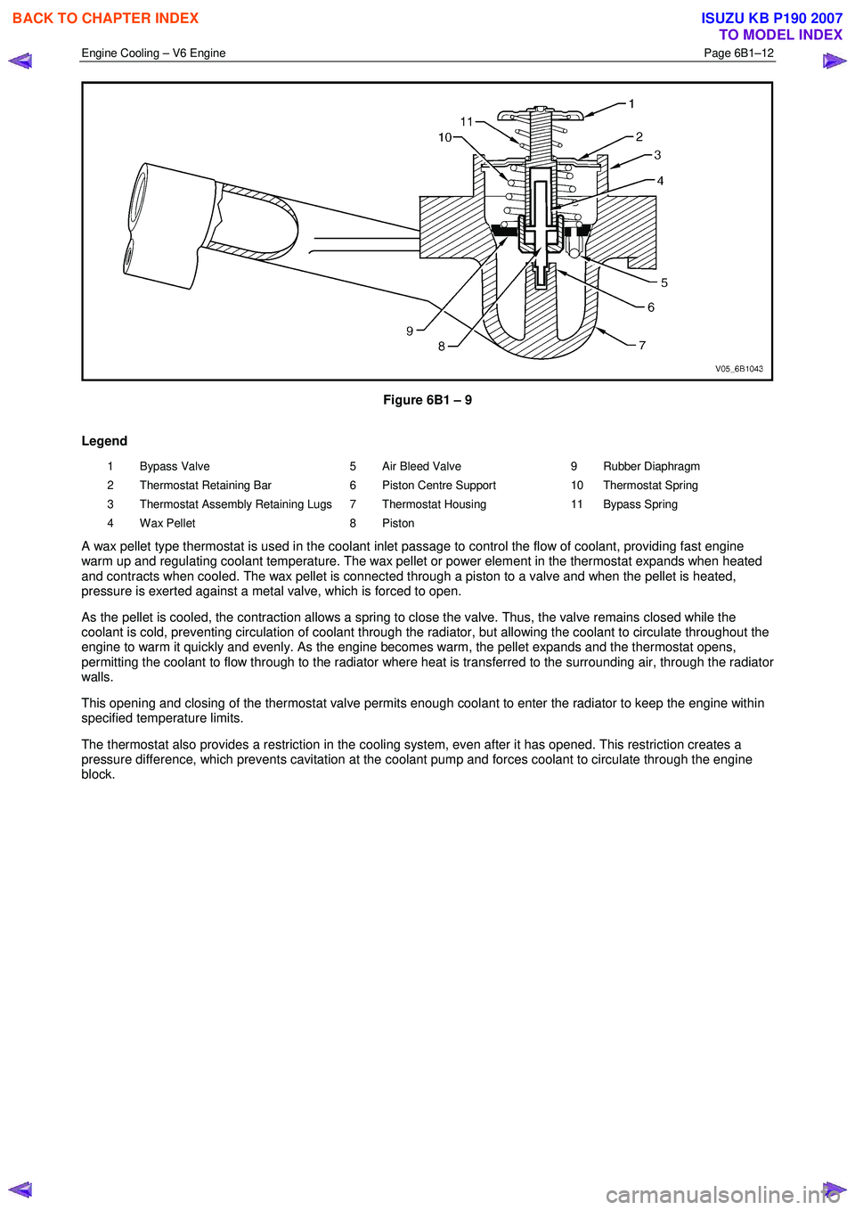
Figure 6B1 – 9
Legend
1 Bypass Valve
2 Thermostat Retaining Bar
3 Thermostat Assembly Retaining Lugs
4 Wax Pellet 5 Air Bleed Valve
6 Piston Centre Support
7 Thermostat Housing
8 Piston 9 Rubber Diaphragm
10 Thermostat Spring
11 Bypass Spring
A wax pellet type thermostat is used in the coolant inlet passage to control the flow of coolant, providing fast engine
warm up and regulating coolant temperature. The wax pellet or power element in the thermostat expands when heated
and contracts when cooled. The wax pellet is connected through a piston to a valve and when the pellet is heated,
pressure is exerted against a metal valve, which is forced to open.
As the pellet is cooled, the contraction allows a spring to close the valve. Thus, the valve remains closed while the
coolant is cold, preventing circulation of coolant through the radiator, but allowing the coolant to circulate throughout the
engine to warm it quickly and evenly. As the engine becomes warm, the pellet expands and the thermostat opens,
permitting the coolant to flow through to the radiator where heat is transferred to the surrounding air, through the radiator
walls.
This opening and closing of the thermostat valve permits enough coolant to enter the radiator to keep the engine within
specified temperature limits.
The thermostat also provides a restriction in the cooling system, even after it has opened. This restriction creates a
pressure difference, which prevents cavitation at the coolant pump and forces coolant to circulate through the engine
block.
BACK TO CHAPTER INDEX
TO MODEL INDEX
ISUZU KB P190 2007
Page 3149 of 6020
Engine Cooling – V6 Engine Page 6B1–14
2.7 Coolant Recovery Reservoir
The coolant is maintained at the ideal level in the radiator by the coolant filler cap and the coolant recovery reservoir,
resulting in increased cooling efficiency.
The coolant recovery reservoir is located on the left-hand side front of the engine compartment, between the radiator
support panel and air cleaner assembly. The coolant recovery reservoir is connected to the radiator overflow connection
by a small diameter hose.
As the engine temperature rises, the coolant is heated and expands. The fluid displaced by expansion flows from the
radiator into the recovery reservoir.
W hen the engine is turned OFF, the coolant contracts as it cools. Coolant is then drawn back into the radiator through
the coolant filler cap atmospheric valve.
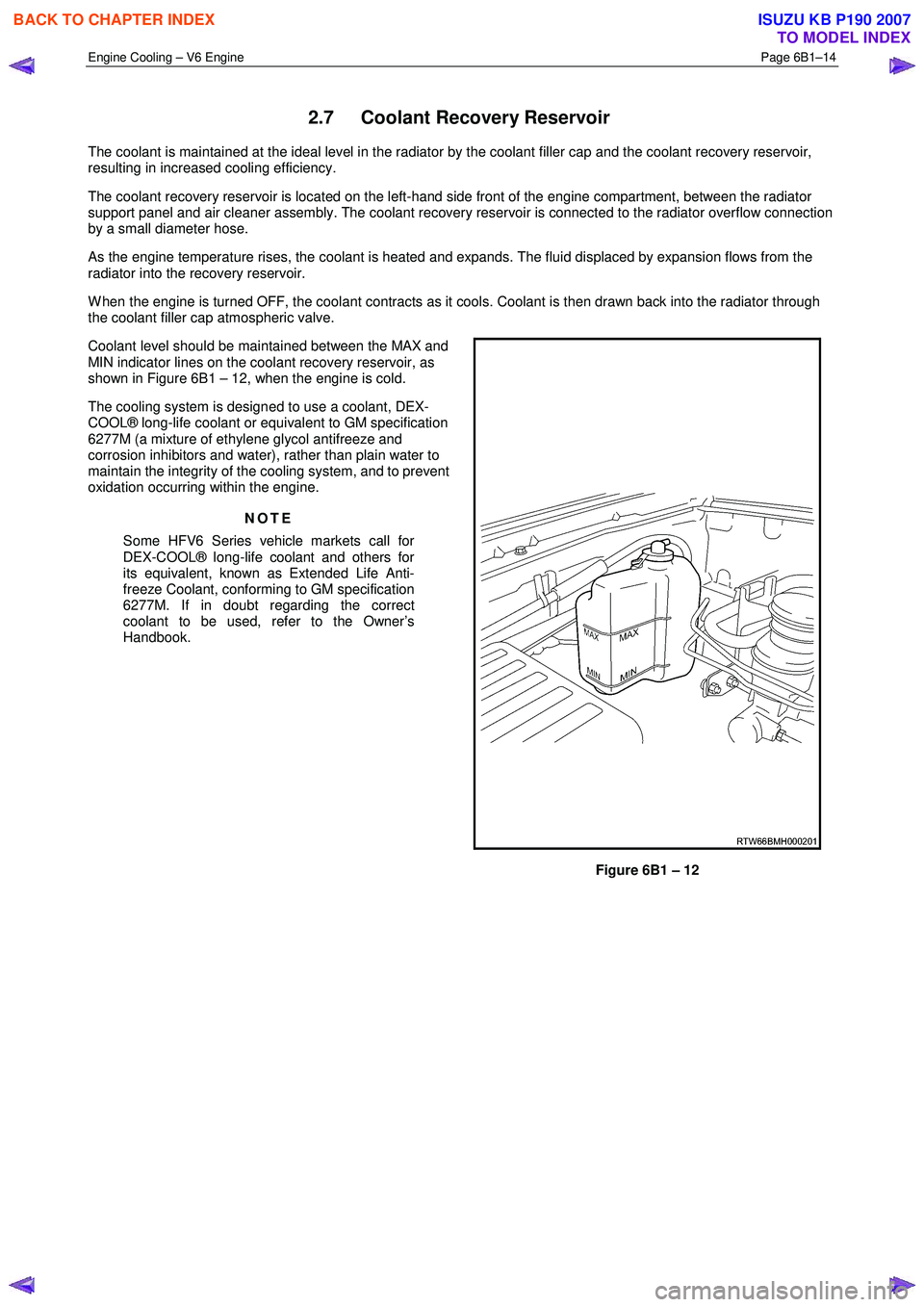
Coolant level should be maintained between the MAX and
MIN indicator lines on the coolant recovery reservoir, as
shown in Figure 6B1 – 12, when the engine is cold.
The cooling system is designed to use a coolant, DEX-
COOL® long-life coolant or equivalent to GM specification
6277M (a mixture of ethylene glycol antifreeze and
corrosion inhibitors and water), rather than plain water to
maintain the integrity of the cooling system, and to prevent
oxidation occurring within the engine.
NOTE
Some HFV6 Series vehicle markets call for
DEX-COOL® long-life coolant and others for
its equivalent, known as Extended Life Anti-
freeze Coolant, conforming to GM specification
6277M. If in doubt regarding the correct
coolant to be used, refer to the Owner’s
Handbook.
Figure 6B1 – 12
BACK TO CHAPTER INDEX
TO MODEL INDEX
ISUZU KB P190 2007
Page 3150 of 6020
Engine Cooling – V6 Engine Page 6B1–15
2.8 Engine Coolant Temperature Sensor
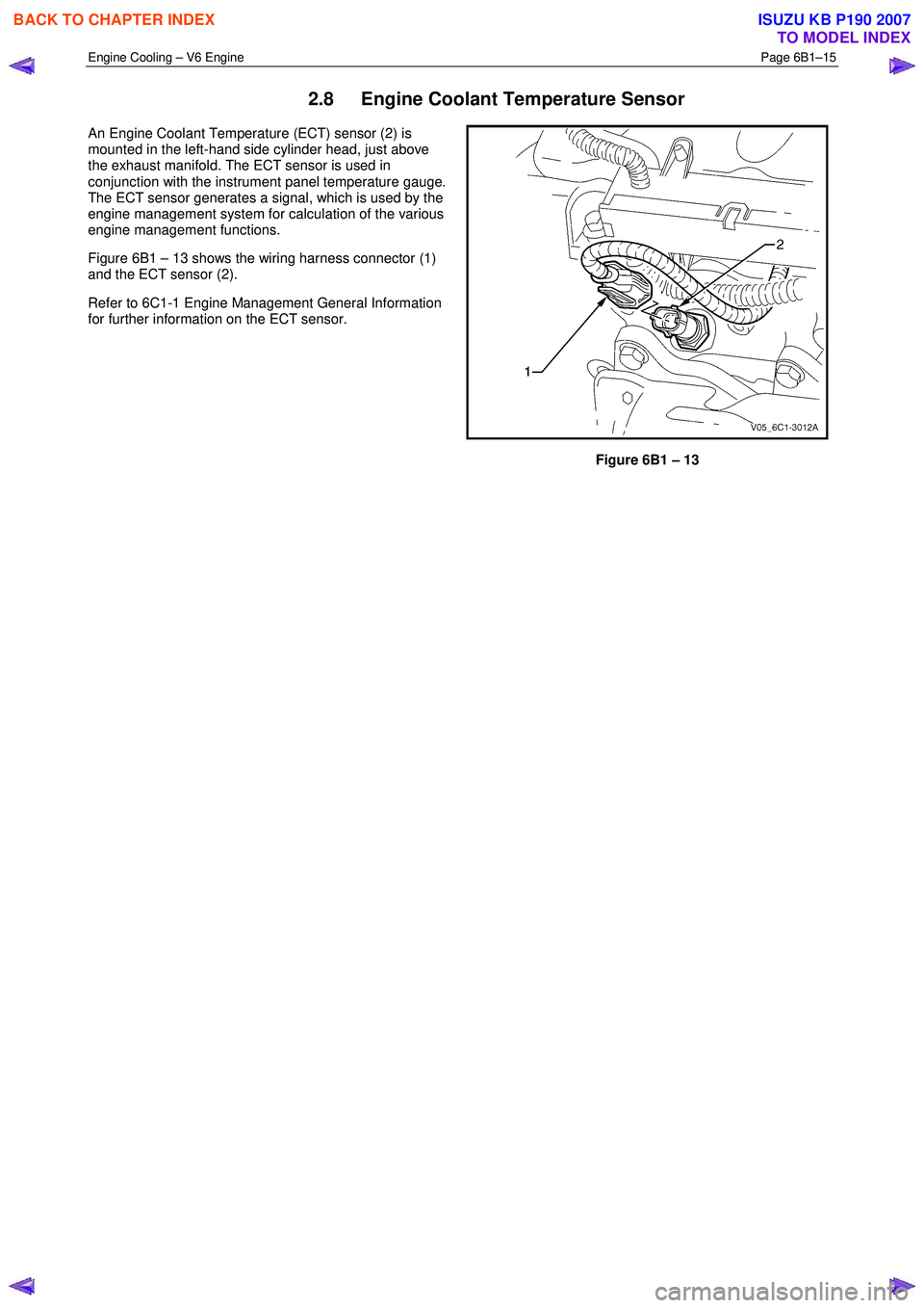
An Engine Coolant Temperature (ECT) sensor (2) is
mounted in the left-hand side cylinder head, just above
the exhaust manifold. The ECT sensor is used in
conjunction with the instrument panel temperature gauge.
The ECT sensor generates a signal, which is used by the
engine management system for calculation of the various
engine management functions.
Figure 6B1 – 13 shows the wiring harness connector (1)
and the ECT sensor (2).
Refer to 6C1-1 Engine Management General Information
for further information on the ECT sensor.
Figure 6B1 – 13
BACK TO CHAPTER INDEX
TO MODEL INDEX
ISUZU KB P190 2007
Page 3153 of 6020
Engine Cooling – V6 Engine Page 6B1–18
Topping Up the Cooling System
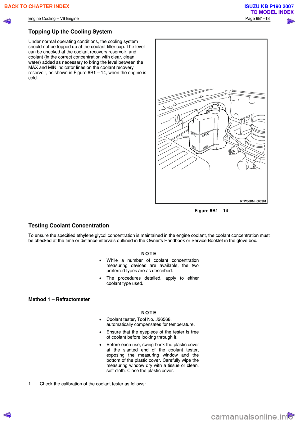
Under normal operating conditions, the cooling system
should not be topped up at the coolant filler cap. The level
can be checked at the coolant recovery reservoir, and
coolant (in the correct concentration with clear, clean
water) added as necessary to bring the level between the
MAX and MIN indicator lines on the coolant recovery
reservoir, as shown in Figure 6B1 – 14, when the engine is
cold.
Figure 6B1 – 14
Testing Coolant Concentration
To ensure the specified ethylene glycol concentration is maintained in the engine coolant, the coolant concentration must
be checked at the time or distance intervals outlined in the Owner’s Handbook or Service Booklet in the glove box.
NOTE
• While a number of coolant concentration
measuring devices are available, the two
preferred types are as described.
• The procedures detailed, apply to either
coolant type used.
Method 1 – Refractometer
NOTE
• Coolant tester, Tool No. J26568,
automatically compensates for temperature.
• Ensure that the eyepiece of the tester is free
of coolant before looking through it.
• Before each use, swing back the plastic cover
at the slanted end of the coolant tester,
exposing the measuring window and the
bottom of the plastic cover. Carefully wipe the
measuring window dry with a tissue or clean,
soft cloth. Close the plastic cover.
1 Check the calibration of the coolant tester as follows:
BACK TO CHAPTER INDEX
TO MODEL INDEX
ISUZU KB P190 2007
Page 3154 of 6020
Engine Cooling – V6 Engine Page 6B1–19
a Place a few drops of distilled water (between 21 and 29° C) onto the measuring window, then close the
plastic cover.
b Point the tester toward any light source, look into the eyepiece and check that the indicated reading is zero. If not, then re-calibrate the tester as detailed at the end of this Test Method, Calibrating the Tester.
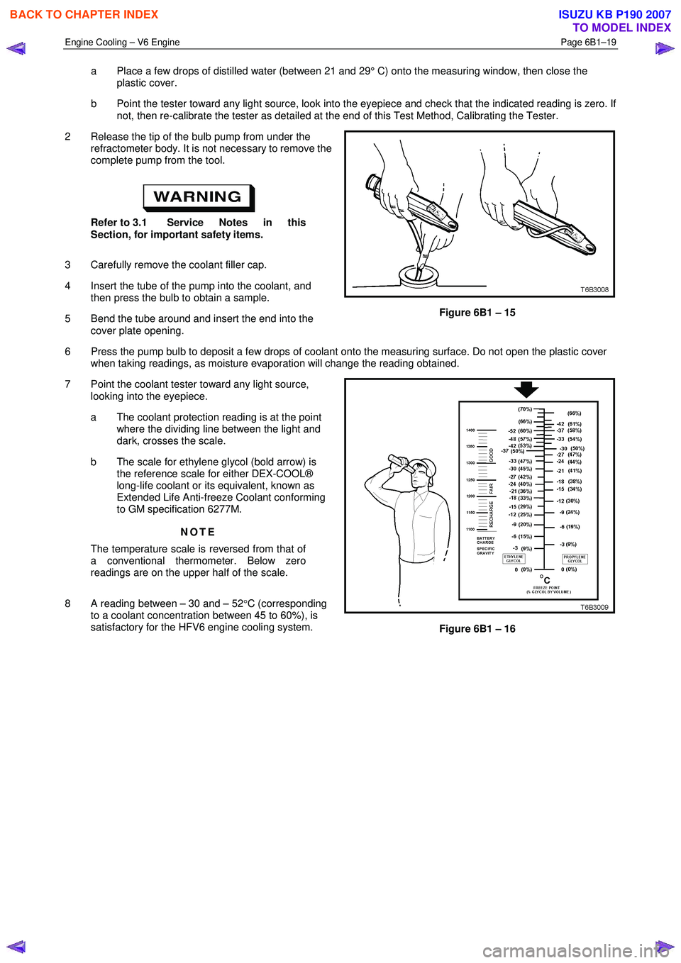
2 Release the tip of the bulb pump from under the refractometer body. It is not necessary to remove the
complete pump from the tool.
Refer to 3.1 Service Notes in this
Section, for important safety items.
3 Carefully remove the coolant filler cap.
4 Insert the tube of the pump into the coolant, and then press the bulb to obtain a sample.
5 Bend the tube around and insert the end into the cover plate opening.
Figure 6B1 – 15
6 Press the pump bulb to deposit a few drops of coolant onto the measuring surface. Do not open the plastic cover when taking readings, as moisture evaporation will change the reading obtained.
7 Point the coolant tester toward any light source, looking into the eyepiece.
a The coolant protection reading is at the point where the dividing line between the light and
dark, crosses the scale.
b The scale for ethylene glycol (bold arrow) is the reference scale for either DEX-COOL®
long-life coolant or its equivalent, known as
Extended Life Anti-freeze Coolant conforming
to GM specification 6277M.
NOTE
The temperature scale is reversed from that of
a conventional thermometer. Below zero
readings are on the upper half of the scale.
8 A reading between – 30 and – 52 °C (corresponding
to a coolant concentration between 45 to 60%), is
satisfactory for the HFV6 engine cooling system.
Figure 6B1 – 16
BACK TO CHAPTER INDEX
TO MODEL INDEX
ISUZU KB P190 2007