2007 ISUZU KB P190 coolant temperature
[x] Cancel search: coolant temperaturePage 3196 of 6020
Engine Cooling – V6 Engine Page 6B1–61
4 Engine Cooling System
Diagnosis
4.1 Poor Heater Operation
Little or no heat coming from the heater, especially at idle could be an indication of a cooling system problem.
As the coolant level begins to get lower than normal, air enters the system to replace the missing coolant. The heater
core is one of the highest parts of the cooling system and therefore, the first area to lose coolant circulation.
At first, with a small amount of coolant loss, lack of heat will be most noticeable at idle. As driving speed increases, the
engine pumps more coolant and more heat is now able to pass through the heater core.
If coolant level drops even lower, heater operation will become less effective, even during normal driving. Cooling and
engine systems can be adversely affected if problem is not corrected before overheating occurs.
4.2 Leaking Cylinder Head Gasket
Combustion gases leaking past the cylinder head gasket can pressurise the cooling system, forcing coolant out of the
system and into the coolant recovery reservoir.
Indications are air bubbles in the coolant or an overflow condition of the recovery reservoir.
4.3 Question the Customer
To avoid needless time and cost in diagnosing cooling system complaints, the customer should be questioned about
driving conditions that place abnormal loads on the cooling system.
1 Is overheating occurring after prolonged idle, in gear, with air conditioning system operating?
If answer is YES – instruct owner on driving techniques that would avoid overheating such as:
• Idle in neutral as much as possible – increase engine rpm to get higher air flow (due to an increase in voltage
to the fan) and coolant flow through the radiator
• Turn air conditioning system off during extended idling periods if overheating is indicated on temperature
gauge. Further diagnostic checks should not be required
2 Is overheating occurring after prolonged driving in slow city traffic, traffic jams, parades, etc?
If answer is YES, explain driving technique to the customer, that would avoid overheating – same as for prolonged idle – No.1. Further diagnostic checks should not be required.
4.4 Diagnostic Chart
If none of the above conditions apply, refer to the following Diagnosis Chart.
To effectively use this chart, question the customer to determine which of the following three categories apply to the
complaint:
1 If complaint is hot indication on temperature gauge.
W as temperature reading accompanied by boiling?
• If answer is YES, go to overheating on diagnosis chart
• If answer is NO, check temperature gauge and sender
2 If complaint is boiling – go to overheating on diagnosis chart.
3 If complaint is coolant loss. Determine if customer is filling the system correctly.
4 If incorrect filling is not the problem, go to coolant loss in the diagnosis chart.
BACK TO CHAPTER INDEX
TO MODEL INDEX
ISUZU KB P190 2007
Page 3197 of 6020

Engine Cooling – V6 Engine Page 6B1–62
Refer to 3.1 Service Notes in this Section, for
important safety items before removing the
coolant filler pressure cap or servicing the
system.
The cooling system is designed to operate at
120 –
––
–
130 kPa and a maximum temperature
not above 130 °
°°
°
C.
Cooling System Diagnosis
Step Action Result Yes No
1
Check Temperature gauge reading High Temp.
Low Temp. Go to Step 2
Go to Step 6 –
2
Check drive belt condition and tension. Refer to 6A1
Engine Mechanical. To Specification Go to Step 3 Replace drive
belt or
tensioner.
3 Check coolant Boiling Go to Step 4 Go to Step 5
4 Check coolant level. Refer to 3.2 Coolant
Maintenance in this Section. Low Go to Step 10 Go to Step 6
5
Check coolant filler cap. Refer to 3.7 Pressure
Testing – Coolant Filler Cap Pressure Testing in this
Section OK? Go to Step 8
Replace
Coolant filler
cap
6 Check thermostat. Refer to 3.8 Thermostat in this
Section. OK? Go to Step 9 Go to Step 13
7
Check Engine Coolant Temperature (ECT) sensor.
Refer to 6C1 Engine Management General Information. Faulty Replace Go to Step 12
8
Check cooling fan operation. Refer to 6C1 Engine
Management General Information. Operational Go to Step 10 Repair
9
Check for collapsed upper or lower radiator hose. Collapsed Replace Go to Step 13
10 Visual system check Leaks Go to Step 13 Go to Step 11
11 Check coolant concentration. Refer to 3.2 Coolant
Maintenance. To Specification Go to Step 12 Correct
Concentration Level
12 Check radiator core for bent fins, dirt, bugs or other
obstructions. Obstructed Clean or
straighten Go to Step 14
13
Pressure Test cooling system. Refer to 3.7 Pressure
Testing in this Section. Leaks Repair System OK
14
If none of the above require repair, the problem is
complex or of a major nature.
Refer to 4.5 Problems Not Requiring Disassembly of
Cooling System or 4.6 Problems Requiring Disassembly
of Cooling System. – – –
BACK TO CHAPTER INDEX
TO MODEL INDEX
ISUZU KB P190 2007
Page 3244 of 6020
Engine Management – V6 – General Information Page 6C1-1–2
3.9 Serial Data Communication System ................................................................................................................... 17
3.10 Self Diagnostics System ..................................................................................................................................... 17
3.11 Service Programming System ..................................................................................................... ....................... 17
3.12 Immobiliser System ............................................................................................................................................. 18
4 Component Description and Operation ............................................................................................ .19
4.1 A/C Refrigerant Pressure Sensor ....................................................................................................................... 19
4.2 Brake Pedal Switch Assembly ............................................................................................................................ 19
Stop Lamp and Initial Brake Apply Switch ....................................................................................... ................. 19
Stop Lamp Switch ............................................................................................................................................ 19
Initial Brake Apply Switch ..................................................................................................... ............................ 19
4.3 Barometric Pressure Sensor..................................................................................................... .......................... 20
4.4 Camshaft Position Sensor .................................................................................................................................. 20
4.5 Crankshaft Position Sensor ................................................................................................................................ 21
4.6 Clutch Pedal Switch Assembly – Manual Vehicles Only ............................................................................ ...... 22
4.7 Engine Control Module........................................................................................................................................ 22
4.8 Engine Coolant Temperature Sensor .............................................................................................. ................... 23
4.9 Electric Cooling Fans .......................................................................................................................................... 23
4.10 Engine Oil Level and Temperature Sensor ........................................................................................ ................ 24
Engine Oil Temperature Sensor ......................................................................................................................... 24
Engine Oil Level Sensor ...................................................................................................................................... 25
4.11 Engine Oil Pressure Sensor..................................................................................................... ........................... 25
4.12 Fuel Injectors........................................................................................................................................................ 26
4.13 Fuel Rail Assembly ............................................................................................................. ................................. 27
4.14 Heated Oxygen Sensors .......................................................................................................... ............................ 27
LSF 4.2 Two-step Planar Heated Oxygen Sensors .................................................................................. ......... 27
LSU 4.2 Wide-band Planar Heated Oxygen Sensors ................................................................................. ....... 29
4.15 Ignition Coil and Spark Plug ............................................................................................................................... 31
4.16 Intake Air Temperature Sensor .................................................................................................. ......................... 32
4.17 Knock Sensor ....................................................................................................................................................... 32
4.18 Mass Air Flow Sensor........................................................................................................... ............................... 33
Air Intake System ................................................................................................................................................. 33
Mass Air Flow Sensor........................................................................................................... ............................... 33
Construction ..................................................................................................................................................... 34
Operation ......................................................................................................................................................... 34
5 Abbreviations and Glossary of Terms ............................................................................................ ...35
BACK TO CHAPTER INDEX
TO MODEL INDEX
ISUZU KB P190 2007
Page 3249 of 6020
Engine Management – V6 – General Information Page 6C1-1–7
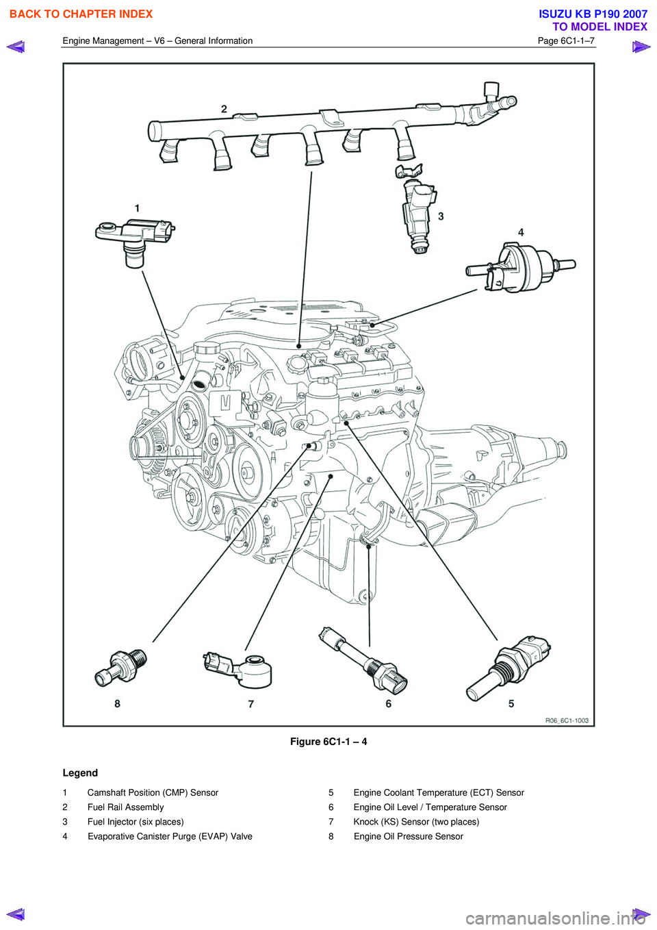
Figure 6C1-1 – 4
Legend
1 Camshaft Position (CMP) Sensor
2 Fuel Rail Assembly
3 Fuel Injector (six places)
4 Evaporative Canister Purge (EVAP) Valve 5 Engine Coolant Temperature (ECT) Sensor
6 Engine Oil Level / Temperature Sensor
7 Knock (KS) Sensor (two places)
8 Engine Oil Pressure Sensor
BACK TO CHAPTER INDEX
TO MODEL INDEX
ISUZU KB P190 2007
Page 3253 of 6020
Engine Management – V6 – General Information Page 6C1-1–11
3.2 Air / Fuel Control System
The engine control module (ECM) controls the amount of air and fuel delivered into each of the engine cylinders. Based
on the various ECM inputs, the ECM switches to the following air / fuel control system mode to provide the optimum air /
fuel ratio under all engine operating conditions.
Starting Mode
W hen the ignition switch is moved to the START position and the engine begins to turn, a prime pulse may be injected to
speed starting. As soon as the ECM receives an input signal from the camshaft position (CMP) and crankshaft position
(CKP) sensor and determines which cylinder is in the firing stroke, the ECM applies a pulse width modulated (PW M)
ground to the injector control circuit. The ECM monitors mass air flow, intake air temperature, engine coolant
temperature, and throttle position to determine the required fuel injector on-time required for starting the engine.
Run Mode
The engine switches to run mode when the engine speed reaches 480 rpm after being started. The run mode has two
sub-modes called Open Loop and Closed Loop.
Open Loop Mode
The heated oxygen sensor (HO2S) does not produce a usable signal voltage output until it reaches operating
temperature. Therefore, while the HO2S is below its operating temperature, the ECM switches to open loop mode.
In open loop, the ECM ignores the signals from the HO2S and calculates the required injector pulse width based
primarily on inputs from the mass air flow (MAF), intake air temperature (IAT), and engine coolant temperature sensors.
The system will stay in the open loop mode until the HO2S produce a usable output.
Closed Loop Mode
Once the HO2S reaches operating temperature and starts producing its own signal voltage output, the ECM switches to
the closed loop mode.
In closed loop mode, the ECM initially calculates injector pulse width based on the same sensors used in open loop, and
additionally the ECM uses the oxygen sensor signals to modify and fine tune the fuel pulse width calculations to precisely
maintain the ideal 14.7 to 1 air / fuel ratio.
Acceleration Mode
The ECM monitors and calculates input signals from the accelerator pedal position (APP) and MAF sensor signals to
determine when the vehicle is being accelerated. If the ECM detects the accelerator pedal is depressed and there is a
demand for the vehicle to accelerate, the ECM switches to acceleration mode. In acceleration mode, the ECM increases
the fuel injector on-time to provide more fuel accordingly.
Deceleration Mode
The ECM monitors and calculates input signals from the APP and MAF sensor signals to determine when the vehicle is
being decelerated. If the ECM detects the vehicle is decelerating, the ECM switches to deceleration mode. In
deceleration mode, the ECM decreases the fuel injector on-time, or disables the fuel injectors for short periods, to reduce
exhaust emissions and improve fuel economy.
Fuel Shut-off Mode
To protect the engine from damage or to improve the vehicle's driveability, the ECM switches to the fuel shut-off mode. In
fuel shut-off mode, the ECM performs the following:
• The ECM disables the six fuel injectors under the following conditions:
− Ignition off – to prevent engine dieseling,
− Ignition on but no ignition reference signal – prevents flooding or backfiring,
− At high engine speed – greater than the red line (rev limiter),
− At high vehicle speed – greater than the rated tire speed (vehicle speed limiter), or
− Extended high speed closed throttle coast-down – reduces engine emissions and increases engine braking.
• The ECM selectively disables the appropriate number of fuel injectors when torque management has been enabled.
BACK TO CHAPTER INDEX
TO MODEL INDEX
ISUZU KB P190 2007
Page 3256 of 6020
Engine Management – V6 – General Information Page 6C1-1–14
Throttle Body Relearn Procedure
The ECM stores values that include the lowest possible TP sensor positions (zero percent), the rest positions (seven
percent), and the spring return rate. These values will only be erased or overwritten if the ECM is reprogrammed or if a
throttle body relearn procedure is performed.
NOTE
If the battery has been disconnected, the ECM
performs a throttle body relearn procedure once
the battery has been reconnected and the ignition
turned on.
The ECM performs a throttle body relearn procedure anytime the ignition is turned on and the following conditions have
been met:
• The engine has been off for greater than 29 seconds,
• The engine speed is less than 40 rpm,
• The vehicle speed is 0 km/h,
• The engine coolant temperature (ECT) is 5 – 60°C; if Tech 2 is used to perform the relearn procedure, the ECT is
5 – 100°C,
• The intake air temperature (IAT) is greater than 5 – 60°C; if Tech 2 is used to perform the relearn procedure, the
IAT is 5 – 100°C,
• The APP sensor angle is less than 15 percent, and
• Ignition voltage is greater than 10 V.
The throttle body relearn procedure is performed 29 seconds after the ignition is turned on. The ECM commands the
throttle plate from the rest position (seven percent open) to full closed (zero percent), then to around 10 percent open.
This procedure takes about six – eight seconds. If any faults occur in the TAC system, a DTC sets. At the start of this
procedure, the Tech 2 TAC Learn Counter parameter should display 0, then count up to 11 after the procedure is
completed. If the counter did not start at 0, or if the counter did not end at 11, a fault has occurred and a DTC should set.
TAC System Default Actions / Reduce Power Modes
The ECM switches to the following reduce power modes if the ECM detects a fault condition in the TAC system:
• If an APP sensor circuit fault or TP sensor circuit fault is detected, the ECM limits engine torque so the vehicle
cannot reach speeds of greater than 100 km/h. The ECM remains in this reduce power mode during the entire
ignition cycle, even if the fault is corrected.
• If there is a fault condition with the throttle actuator control circuits, a throttle actuator command vs. actual position
fault, a return spring check fault, or a TP sensor one circuit fault, the ECM limits engine speed to 2500 rpm and
three – six fuel injectors are randomly disabled. At this time the reduce power indicator is commanded on. The
ECM remains in the reduce power mode during the entire ignition cycle even if the fault is corrected.
NOTE
If a TP sensor one or throttle actuator control
circuit fault is present at the time the vehicle is at
idle, with no accelerator pedal angle, the engine
may stall.
Forced Engine Shutdown
A further safety feature which is built into the TAC system is the ECM will initiate an engine shut down if, the ECM’s
internal monitoring functions detects a serious internal fault, the fuel injectors will be turned off.
3.6 Cruise Control System
The cruise control system integrates with the engine control module (ECM) through the powertrain interface module
(PIM), to control the electronic throttle actuator and maintain the vehicle at the speed set by the driver.
BACK TO CHAPTER INDEX
TO MODEL INDEX
ISUZU KB P190 2007
Page 3258 of 6020
Engine Management – V6 – General Information Page 6C1-1–16
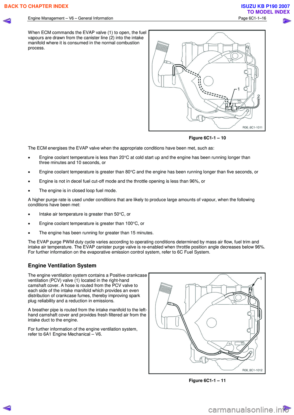
W hen ECM commands the EVAP valve (1) to open, the fuel
vapours are drawn from the canister line (2) into the intake
manifold where it is consumed in the normal combustion
process.
Figure 6C1-1 – 10
The ECM energises the EVAP valve when the appropriate conditions have been met, such as:
• Engine coolant temperature is less than 20 °C at cold start up and the engine has been running longer than
three minutes and 10 seconds, or
• Engine coolant temperature is greater than 80 °C and the engine has been running longer than five seconds, or
• Engine is not in decel fuel cut-off mode and the throttle opening is less than 96%, or
• The engine is in closed loop fuel mode.
A higher purge rate is used under conditions that are likely to produce large amounts of vapour, when the following
conditions have been met:
• Intake air temperature is greater than 50 °C, or
• Engine coolant temperature is greater than 100 °C, or
• The engine has been running for greater than 15 minutes.
The EVAP purge PW M duty cycle varies according to operating conditions determined by mass air flow, fuel trim and
intake air temperature. The EVAP canister purge valve is re-enabled when throttle position angle decreases below 96%.
For further information on the evaporative emission control system, refer to 6C Fuel System.
Engine Ventilation System
The engine ventilation system contains a Positive crankcase
ventilation (PCV) valve (1) located in the right-hand
camshaft cover. A hose is routed from the PCV valve to
each side of the intake manifold which provides an even
distribution of crankcase fumes, thereby improving spark
plug reliability and a reduction in emissions.
A breather pipe is routed from the intake manifold to the left-
hand camshaft cover and provides fresh filtered air from the
intake duct to the engine.
For further information of the engine ventilation system,
refer to 6A1 Engine Mechanical – V6.
Figure 6C1-1 – 11
BACK TO CHAPTER INDEX
TO MODEL INDEX
ISUZU KB P190 2007
Page 3265 of 6020
Engine Management – V6 – General Information Page 6C1-1–23
4.8 Engine Coolant Temperature Sensor
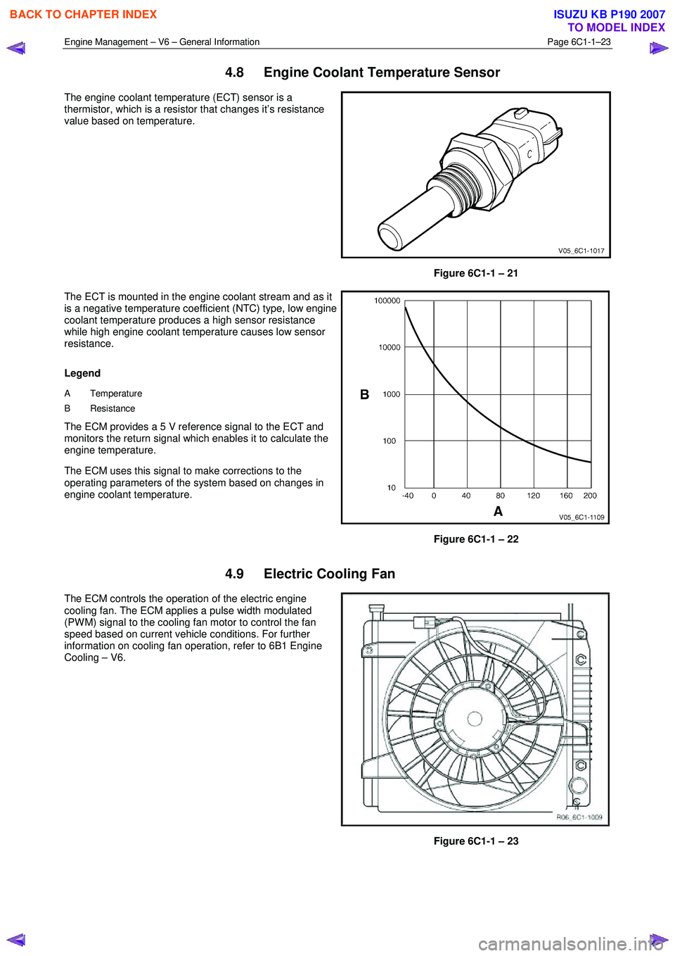
The engine coolant temperature (ECT) sensor is a
thermistor, which is a resistor that changes it’s resistance
value based on temperature.
Figure 6C1-1 – 21
The ECT is mounted in the engine coolant stream and as it
is a negative temperature coefficient (NTC) type, low engine
coolant temperature produces a high sensor resistance
while high engine coolant temperature causes low sensor
resistance.
Legend
A Temperature
B Resistance
The ECM provides a 5 V reference signal to the ECT and
monitors the return signal which enables it to calculate the
engine temperature.
The ECM uses this signal to make corrections to the
operating parameters of the system based on changes in
engine coolant temperature.
Figure 6C1-1 – 22
4.9 Electric Cooling Fan
The ECM controls the operation of the electric engine
cooling fan. The ECM applies a pulse width modulated
(PW M) signal to the cooling fan motor to control the fan
speed based on current vehicle conditions. For further
information on cooling fan operation, refer to 6B1 Engine
Cooling – V6.
Figure 6C1-1 – 23
BACK TO CHAPTER INDEX
TO MODEL INDEX
ISUZU KB P190 2007