2007 ISUZU KB P190 coolant temperature
[x] Cancel search: coolant temperaturePage 3320 of 6020
Engine Management – V6 – Diagnostics Page 6C1-2–42
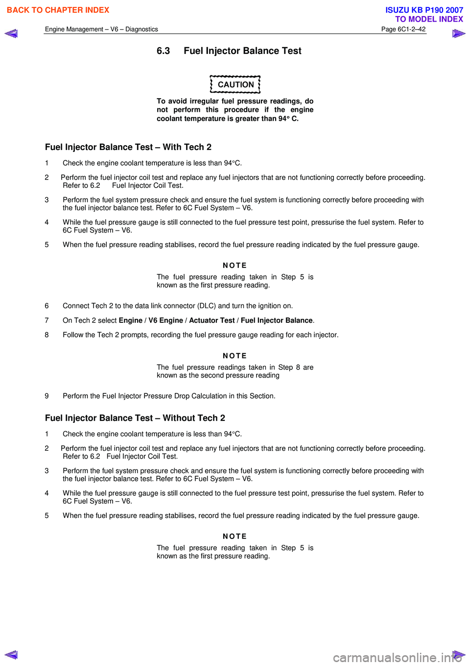
6.3 Fuel Injector Balance Test
To avoid irregular fuel pressure readings, do
not perform this procedure if the engine
coolant temperature is greater than 94 °
°°
°
C.
Fuel Injector Balance Test – With Tech 2
1 Check the engine coolant temperature is less than 94 °C.
2 Perform the fuel injector coil test and replace any fuel injectors that are not functioning correctly before proceeding. Refer to 6.2 Fuel Injector Coil Test.
3 Perform the fuel system pressure check and ensure the fuel system is functioning correctly before proceeding with the fuel injector balance test. Refer to 6C Fuel System – V6.
4 W hile the fuel pressure gauge is still connected to the fuel pressure test point, pressurise the fuel system. Refer to 6C Fuel System – V6.
5 W hen the fuel pressure reading stabilises, record the fuel pressure reading indicated by the fuel pressure gauge.
NOTE
The fuel pressure reading taken in Step 5 is
known as the first pressure reading.
6 Connect Tech 2 to the data link connector (DLC) and turn the ignition on.
7 On Tech 2 select Engine / V6 Engine / Actuator Test / Fuel Injector Balance .
8 Follow the Tech 2 prompts, recording the fuel pressure gauge reading for each injector.
NOTE
The fuel pressure readings taken in Step 8 are
known as the second pressure reading
9 Perform the Fuel Injector Pressure Drop Calculation in this Section.
Fuel Injector Balance Test – Without Tech 2
1 Check the engine coolant temperature is less than 94 °C.
2 Perform the fuel injector coil test and replace any fuel injectors that are not functioning correctly before proceeding. Refer to 6.2 Fuel Injector Coil Test.
3 Perform the fuel system pressure check and ensure the fuel system is functioning correctly before proceeding with the fuel injector balance test. Refer to 6C Fuel System – V6.
4 W hile the fuel pressure gauge is still connected to the fuel pressure test point, pressurise the fuel system. Refer to 6C Fuel System – V6.
5 W hen the fuel pressure reading stabilises, record the fuel pressure reading indicated by the fuel pressure gauge.
NOTE
The fuel pressure reading taken in Step 5 is
known as the first pressure reading.
BACK TO CHAPTER INDEX
TO MODEL INDEX
ISUZU KB P190 2007
Page 3325 of 6020
Engine Management – V6 – Diagnostics Page 6C1-2–47
6.7 Throttle Body Relearn
A throttle body relearn procedure is performed in one of two ways:
• Engine Control Module initiated throttle body relearn, or
• Tech 2 initiated throttle body relearn.
Engine Control Module Throttle Body Relearn
The engine control module (ECM) will automatically perform a throttle body relearn procedure if either of the following
conditions exist:
• The battery has been disconnected, or
• The ignition switch is in the ON position for greater than 29 seconds, and the following conditions are met:
− Engine speed is less than 40 rpm,
− Vehicle speed is 0 km/h,
− Engine coolant temperature is 5 – 60°C,
− Intake air temperature is 5 – 60°C,
− Accelerator pedal position sensor angle is less than 14.9%, and
− Ignition voltage is greater than 10 V.
Tech 2 Throttle Body Relearn
To perform a throttle body relearn using Tech 2, complete the following procedure:
NOTE
Tech 2 will not initiate a throttle body relearn if
the engine is running.
1 Connect Tech 2 to the data link connector (DLC) and turn the ignition on.
2 On Tech 2 select Engine / Programming / Throttle Body Relearn.
3 W hen Tech 2 displays ‘Do you really want to Reset?’, press the ‘Yes’ soft key.
4 W hen Tech 2 displays ‘Programming Completed’, and the electronic throttle control value displayed by Tech 2 is ‘11’, press the ‘Confirm’ soft key to return to the Tech 2 Programming screen.
5 The throttle body relearn is now complete.
6.8 Electronic Ignition (EI) System Diagnosis
Circuit Description
The engine control module (ECM) controls the ignition coils by pulsing the ignition control (IC) circuits, which triggers an
ignition coil and fires the spark plug. The ECM controls the sequencing and the timing of each ignition coil. The ignition
system consist of the following components:
• The six ignition coils
• The crankshaft position (CKP) sensor
• The four camshaft position (CMP) sensors
• The ECM
The ignition coils use the following circuits:
• An IC circuit
• An ignition 1 voltage circuit
• Two ground circuits
BACK TO CHAPTER INDEX
TO MODEL INDEX
ISUZU KB P190 2007
Page 3329 of 6020
Engine Management – V6 – Diagnostics Page 6C1-2–51
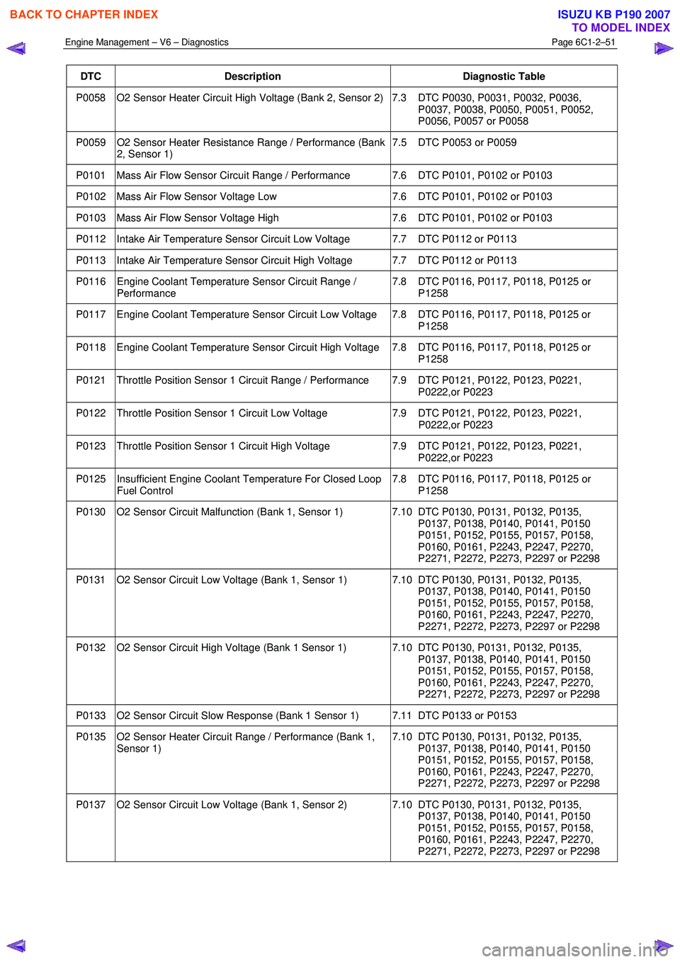
DTC Description Diagnostic Table
P0058 O2 Sensor Heater Circuit High Voltage (Bank 2, Sensor 2) 7.3 DTC P0030, P0031, P0032, P0036,
P0037, P0038, P0050, P0051, P0052,
P0056, P0057 or P0058
P0059 O2 Sensor Heater Resistance Range / Performance (Bank 2, Sensor 1) 7.5 DTC P0053 or P0059
P0101 Mass Air Flow Sensor Circuit Range / Performance 7.6 DTC P0101, P0102 or P0103
P0102 Mass Air Flow Sensor Voltage Low
7.6 DTC P0101, P0102 or P0103
P0103 Mass Air Flow Sensor Voltage High 7.6 DTC P0101, P0102 or P0103
P0112 Intake Air Temperature Sensor Circuit Low Voltage 7.7 DTC P0112 or P0113
P0113 Intake Air Temperature Sensor Circuit High Voltage 7.7 DTC P0112 or P0113
P0116 Engine Coolant Temperature Sensor Circuit Range /
Performance 7.8 DTC P0116, P0117, P0118, P0125 or
P1258
P0117 Engine Coolant Temperature Sensor Circuit Low Voltage 7.8 DTC P0116, P0117, P0118, P0125 or P1258
P0118 Engine Coolant Temperature Sensor Circuit High Voltage 7.8 DTC P0116, P0117, P0118, P0125 or P1258
P0121 Throttle Position Sensor 1 Circuit Range / Performance 7.9 DTC P0121, P0122, P0123, P0221, P0222,or P0223
P0122 Throttle Position Sensor 1 Circuit Low Voltage 7.9 DTC P0121, P0122, P0123, P0221,
P0222,or P0223
P0123 Throttle Position Sensor 1 Circuit High Voltage 7.9 DTC P0121, P0122, P0123, P0221,
P0222,or P0223
P0125 Insufficient Engine Coolant Temperature For Closed Loop Fuel Control 7.8 DTC P0116, P0117, P0118, P0125 or
P1258
P0130 O2 Sensor Circuit Malfunction (Bank 1, Sensor 1) 7.10 DTC P0130, P0131, P0132, P0135, P0137, P0138, P0140, P0141, P0150
P0151, P0152, P0155, P0157, P0158,
P0160, P0161, P2243, P2247, P2270,
P2271, P2272, P2273, P2297 or P2298
P0131 O2 Sensor Circuit Low Voltage (Bank 1, Sensor 1) 7.10 DTC P0130, P0131, P0132, P0135, P0137, P0138, P0140, P0141, P0150
P0151, P0152, P0155, P0157, P0158,
P0160, P0161, P2243, P2247, P2270,
P2271, P2272, P2273, P2297 or P2298
P0132 O2 Sensor Circuit High Voltage (Bank 1 Sensor 1) 7.10 DTC P0130, P0131, P0132, P0135, P0137, P0138, P0140, P0141, P0150
P0151, P0152, P0155, P0157, P0158,
P0160, P0161, P2243, P2247, P2270,
P2271, P2272, P2273, P2297 or P2298
P0133 O2 Sensor Circuit Slow Response (Bank 1 Sensor 1) 7.11 DTC P0133 or P0153
P0135 O2 Sensor Heater Circuit Range / Performance (Bank 1, Sensor 1) 7.10 DTC P0130, P0131, P0132, P0135,
P0137, P0138, P0140, P0141, P0150
P0151, P0152, P0155, P0157, P0158,
P0160, P0161, P2243, P2247, P2270,
P2271, P2272, P2273, P2297 or P2298
P0137 O2 Sensor Circuit Low Voltage (Bank 1, Sensor 2) 7.10 DTC P0130, P0131, P0132, P0135, P0137, P0138, P0140, P0141, P0150
P0151, P0152, P0155, P0157, P0158,
P0160, P0161, P2243, P2247, P2270,
P2271, P2272, P2273, P2297 or P2298
BACK TO CHAPTER INDEX
TO MODEL INDEX
ISUZU KB P190 2007
Page 3334 of 6020
Engine Management – V6 – Diagnostics Page 6C1-2–56
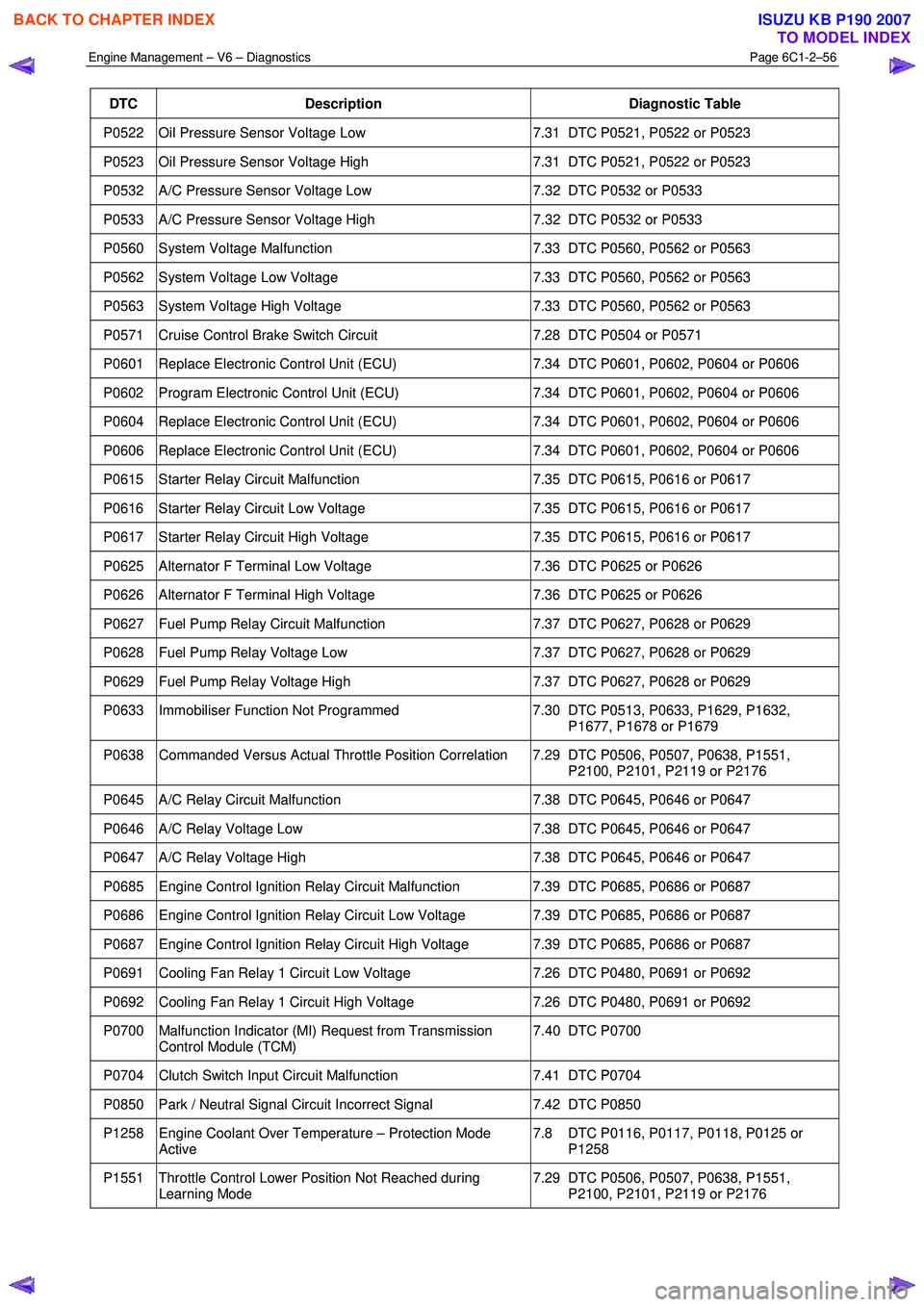
DTC Description Diagnostic Table
P0522 Oil Pressure Sensor Voltage Low 7.31 DTC P0521, P0522 or P0523
P0523 Oil Pressure Sensor Voltage High 7.31 DTC P0521, P0522 or P0523
P0532 A/C Pressure Sensor Voltage Low 7.32 DTC P0532 or P0533
P0533 A/C Pressure Sensor Voltage High 7.32 DTC P0532 or P0533
P0560 System Voltage Malfunction 7.33 DTC P0560, P0562 or P0563
P0562 System Voltage Low Voltage 7.33 DTC P0560, P0562 or P0563
P0563 System Voltage High Voltage 7.33 DTC P0560, P0562 or P0563
P0571 Cruise Control Brake Switch Circuit 7.28 DTC P0504 or P0571
P0601 Replace Electronic Control Unit (ECU) 7.34 DTC P0601, P0602, P0604 or P0606
P0602 Program Electronic Control Unit (ECU) 7.34 DTC P0601, P0602, P0604 or P0606
P0604 Replace Electronic Control Unit (ECU) 7.34 DTC P0601, P0602, P0604 or P0606
P0606 Replace Electronic Control Unit (ECU) 7.34 DTC P0601, P0602, P0604 or P0606
P0615 Starter Relay Circuit Malfunction 7.35 DTC P0615, P0616 or P0617
P0616 Starter Relay Circuit Low Voltage 7.35 DTC P0615, P0616 or P0617
P0617 Starter Relay Circuit High Voltage 7.35 DTC P0615, P0616 or P0617
P0625 Alternator F Terminal Low Voltage 7.36 DTC P0625 or P0626
P0626 Alternator F Terminal High Voltage 7.36 DTC P0625 or P0626
P0627 Fuel Pump Relay Circuit Malfunction 7.37 DTC P0627, P0628 or P0629
P0628 Fuel Pump Relay Voltage Low 7.37 DTC P0627, P0628 or P0629
P0629 Fuel Pump Relay Voltage High 7.37 DTC P0627, P0628 or P0629
P0633 Immobiliser Function Not Programmed 7.30 DTC P0513, P0633, P1629, P1632,
P1677, P1678 or P1679
P0638 Commanded Versus Actual Throttle Position Correlation 7.29 DTC P0506, P0507, P0638, P1551, P2100, P2101, P2119 or P2176
P0645 A/C Relay Circuit Malfunction 7.38 DTC P0645, P0646 or P0647
P0646 A/C Relay Voltage Low 7.38 DTC P0645, P0646 or P0647
P0647 A/C Relay Voltage High 7.38 DTC P0645, P0646 or P0647
P0685 Engine Control Ignition Relay Circuit Malfunction 7.39 DTC P0685, P0686 or P0687
P0686 Engine Control Ignition Relay Circuit Low Voltage 7.39 DTC P0685, P0686 or P0687
P0687 Engine Control Ignition Relay Circuit High Voltage 7.39 DTC P0685, P0686 or P0687
P0691 Cooling Fan Relay 1 Circuit Low Voltage 7.26 DTC P0480, P0691 or P0692
P0692 Cooling Fan Relay 1 Circuit High Voltage 7.26 DTC P0480, P0691 or P0692
P0700 Malfunction Indicator (MI) Request from Transmission
Control Module (TCM) 7.40 DTC P0700
P0704 Clutch Switch Input Circuit Malfunction
7.41 DTC P0704
P0850 Park / Neutral Signal Circuit Incorrect Signal 7.42 DTC P0850
P1258 Engine Coolant Over Temperature – Protection Mode
Active 7.8 DTC P0116, P0117, P0118, P0125 or
P1258
P1551 Throttle Control Lower Position Not Reached during Learning Mode 7.29 DTC P0506, P0507, P0638, P1551,
P2100, P2101, P2119 or P2176
BACK TO CHAPTER INDEX
TO MODEL INDEX
ISUZU KB P190 2007
Page 3339 of 6020
Engine Management – V6 – Diagnostics Page 6C1-2–61
• DTCs P0341, P0342, P0343, ran and passed:
• The engine is running.
• The ECM has learned the camshafts position.
DTC P0016
Run continuously once the following conditions are met.
• DTCs P0335, P0336, P0338, P0341, P0342 and P0343 ran and passed:
• The calculated engine oil temperature is less than 95 °C.
• The engine coolant temperature is 20 – 90 °C.
• The engine is running for greater than 5 seconds.
Conditions for Setting the DTC
DTC P0008
The ECM detects that both camshafts on bank 1 of the engine are misaligned with the crankshaft.
DTC P0009
The ECM detects that both camshafts on bank 2 of the engine are misaligned with the crankshaft.
DTC P0016
The ECM detects the following deviation in the correlation between the camshaft position and the crankshaft position for
greater than 10 minutes:
• a camshaft position is too advanced in relationship to the crankshaft, or
• a camshaft position is too retarded in relationship to the crankshaft.
Conditions for Clearing DTC
The CKP / CMP sensor correlation DTCs are Type B DTCs. Refer to 1.4 Diagnostic Trouble Codes in this Section, for
action taken when Type B DTCs set and conditions for clearing Type B DTCs.
Additional Information
• Refer to 6C1-1 Engine Management – V6 – General Information for details of the CMP system operation.
• Inspect the engine for recent engine mechanical repairs. Incorrect camshaft, camshaft actuator or timing chain
installation will trigger these DTCs.
• The engine oil condition has a major impact on the operation of the camshaft actuator.
• A low oil level may set these DTCs.
• For an intermittent fault condition, refer to 5.2 Intermittent Fault Conditions in this Section.
• Since fault condition in a wiring connector may trigger DTCs, always test the connectors related to this diagnostic
procedure for shorted terminals or poor wiring connection before replacing any component. Refer to 8A Electrical -
Body and Chassis for information on electrical fault diagnosis.
• To assist diagnosis, refer to 3 W iring Diagrams and Connector Charts in this Section, for the system wiring
diagram and connector charts.
Test Description
The following numbers refer to the step numbers in the diagnostic table:
3 A fault condition in any of the listed sensors will trigger these DTCs.
5 Incorrect camshaft, camshaft actuator or timing chain installation will trigger these DTCs.
BACK TO CHAPTER INDEX
TO MODEL INDEX
ISUZU KB P190 2007
Page 3353 of 6020
Engine Management – V6 – Diagnostics Page 6C1-2–75
Step Action Yes No
9 1 Using Tech 2, clear the DTCs.
2 Switch off the ignition for 30 seconds.
3 Start the engine.
4 Operate the vehicle within the conditions for running the DTC.
Does any of the IAT sensor DTCs fail this ignition cycle? Go to Step 2 Go to Step 10
10 Using Tech 2, select the DTC display function.
Does Tech 2 display any DTCs? Go to the
appropriate DTC
Table in this Section System OK
When all diagnosis and repairs are completed, check the system for correct operation.
7.8 DTC P0116, P0117, P0118, P0125 or
P1258
DTC Descriptors
This diagnostic procedure supports the following DTCs:
• DTC P0116 – Engine Coolant Temperature Sensor Circuit Range / Performance
• DTC P0117 – Engine Coolant Temperature Sensor Circuit Low Voltage
• DTC P0118 – Engine Coolant Temperature Sensor Circuit High Voltage
• DTC P0125 – Insufficient Engine Coolant Temperature For Closed Loop Fuel Control
• DTC P1258 – Engine Coolant Over Temperature - Protection Mode Active
Circuit Description
The ECM applies a reference 5 V to the engine coolant temperature (ECT) sensor signal circuit and ground through the
low reference circuit. The ECT sensor is a variable resistor that measures the temperature of the engine coolant.
• Increased temperature in the engine coolant decreases the resistance value of the ECT sensor. This increases the
ECT sensor pull-down rate to ground. Therefore, the higher the engine coolant, the lower the signal voltage output
of the ECT sensor.
• Decreased temperature in the engine coolant increases the resistance value of the ECT sensor. This reduces the
ECT sensor pull-down rate to ground. Therefore, the lower the engine coolant temperature, the higher the signal
voltage output of the ECT sensor.
An ECT sensor DTC sets if the ECM detects the engine coolant temperature is outside the predetermined range.
Conditions for Running the DTC
DTC P0116
Runs continuously when the engine is running.
DTC P0117, P0118 and P1258
Runs continuously when the ignition is switched on.
DTC P00125
Runs continuously once the following conditions are met:
• DTCs P0112, P0113, P0117 or P0118 are not set.
• The engine is running.
BACK TO CHAPTER INDEX
TO MODEL INDEX
ISUZU KB P190 2007
Page 3354 of 6020
Engine Management – V6 – Diagnostics Page 6C1-2–76
Conditions for Setting the DTC
DTC P0116
The ECM detects the engine coolant temperature sensor value is 10°C less than the minimum calculated engine
temperature.
DTC P0117
The ECM detects the engine coolant temperature is greater than 140 °C for longer than 3 seconds.
DTC P0118
The ECM detects the engine coolant temperature is less than -39 °C for longer than 3 seconds.
DTC P0125
The ECM determines the calculated engine temperature by measuring the amount of airflow into the engine. This DTC
sets if the ECM detects the actual ECT sensor is not within 10ºC of the calculated engine temperature for approximately
2 – 5 minutes.
DTC P1258
The ECM detects the engine coolant temperature is greater than 131 °C for longer than 2 seconds.
Conditions for Clearing the DTC
The ECT sensor DTCs are Type B DTCs. Refer to 1.4 Diagnostic Trouble Codes in this Section, for action taken when a
Type B DTC sets and conditions for clearing Type B DTC.
Additional Information
• Refer to 6C1-1 Engine Management – V6 – General Information for details of the ECT sensor operation.
• For an intermittent fault condition, refer to 5.2 Intermittent Fault Conditions in this Section.
• DTCs P0116, P0117, P0118 and P0125 diagnostic table is developed with the assumption the engine cooling
system is functioning correctly. Therefore, rectify any engine cooling system fault conditions before proceeding
with this diagnostic table.
• Test the ECT sensor using the ECT Temperature vs. Resistance in 6C1-3 Engine Management –V6 – Service
Operations. If the engine has sat overnight, the ECT sensor should display within 3 °C of the IAT sensor values.
W hen the engine is first started, the ECT should rise steadily to about 90 °C then stabilise when thermostat opens.
• Since fault condition in a wiring connector may trigger DTCs, always test the connectors related to this diagnostic
procedure for shorted terminals or poor wiring connection before replacing any component. Refer to 8A Electrical -
Body and Chassis for information on electrical fault diagnosis.
• To assist diagnosis, refer to 3 W iring Diagrams and Connector Charts in this Section, for the system wiring
diagram and connector charts.
Test Description
The following numbers refer to the step numbers in the diagnostic table:
2 A fault condition in the engine cooling system may trigger these DTCs.
7 The ECT sensor low reference circuit is shared with other components. DTC P0118 may set if the shared low reference circuit is shorted to voltage. Test the low reference circuit of all components that share this circuit to find
the source of the fault condition.
DTC P0116, P0117, P0118, P0125 and P1258 Diagnostic Table
Step Action Yes No
1 Has the Diagnostic System Check been performed?
Go to Step 2 Refer to
4.4 Diagnostic
System Check in this Section
BACK TO CHAPTER INDEX
TO MODEL INDEX
ISUZU KB P190 2007
Page 3362 of 6020
Engine Management – V6 – Diagnostics Page 6C1-2–84
• The calculated exhaust temperature is 250ºC – 800ºC.
• The engine coolant temperature is less than 40ºC at start-up and greater than 60ºC when the ignition was turned
off last ignition cycle.
• The fuel tank level is greater than 25 percent.
DTC P0138 and P0158
Run continuously once the following conditions are met:
• The engine is operating for longer than two minutes.
• The ignition voltage is 10.0 – 16.0 V.
• The HO2S is at operating temperature.
• The calculated exhaust temperature is 250ºC – 800ºC.
DTC P0140 and P0160
Run continuously once the following conditions are met for longer than 90 seconds:
• The engine is operating.
• The ignition voltage is 10.0 – 16.0 V.
• The calculated exhaust temperature is 250º C – 800º C.
DTC P0141 and P0161
Run continuously once the following conditions are met:
• DTCs P0036, P0037, P0038, P0056, P0057, and P0058 ran and passed.
• DTCs P0137, P0138, P0140, P0157, P0158, or P0160 are not set.
• The engine is operating.
• The ECM internal sensing element resistance is valid.
• The fuel system is not in decel fuel shut-off.
• The intake air temperature is greater than -7ºC.
• If the engine is operating and the ignition is turned off, the engine must be off for at least 5 minutes for this DTC to
run.
• The ignition voltage is 10.0 – 16.0 V.
• The calculated exhaust temperature is 360ºC – 500ºC.
DTC P2243 and P2247
Run continuously once the following conditions are met:
• DTCs P0030, P0031, P0032, P0050, P0051 and P0052 ran and passed.
• The ECM internal sensing element resistance is greater than 570 Ω.
• The HO2S is at operating temperature.
DTC P2270 and P2272
Run continuously once the following conditions are met:
• DTCs P0036, P0037, P0038, P0056, P0057, P0058, P0137, P0138, P0140, P0141, P0157, P0158, P0160, P0161,
P0342, P0343, P0443, P0458 and P0459 ran and passed.
• The engine is running.
• The HO2S 2 are at operating temperature for longer than 10 seconds.
• The long term fuel control is enabled.
BACK TO CHAPTER INDEX
TO MODEL INDEX
ISUZU KB P190 2007