2007 ISUZU KB P190 coolant temperature
[x] Cancel search: coolant temperaturePage 3541 of 6020
Engine Management – V6 – Service Operations Page 6C1-3–17
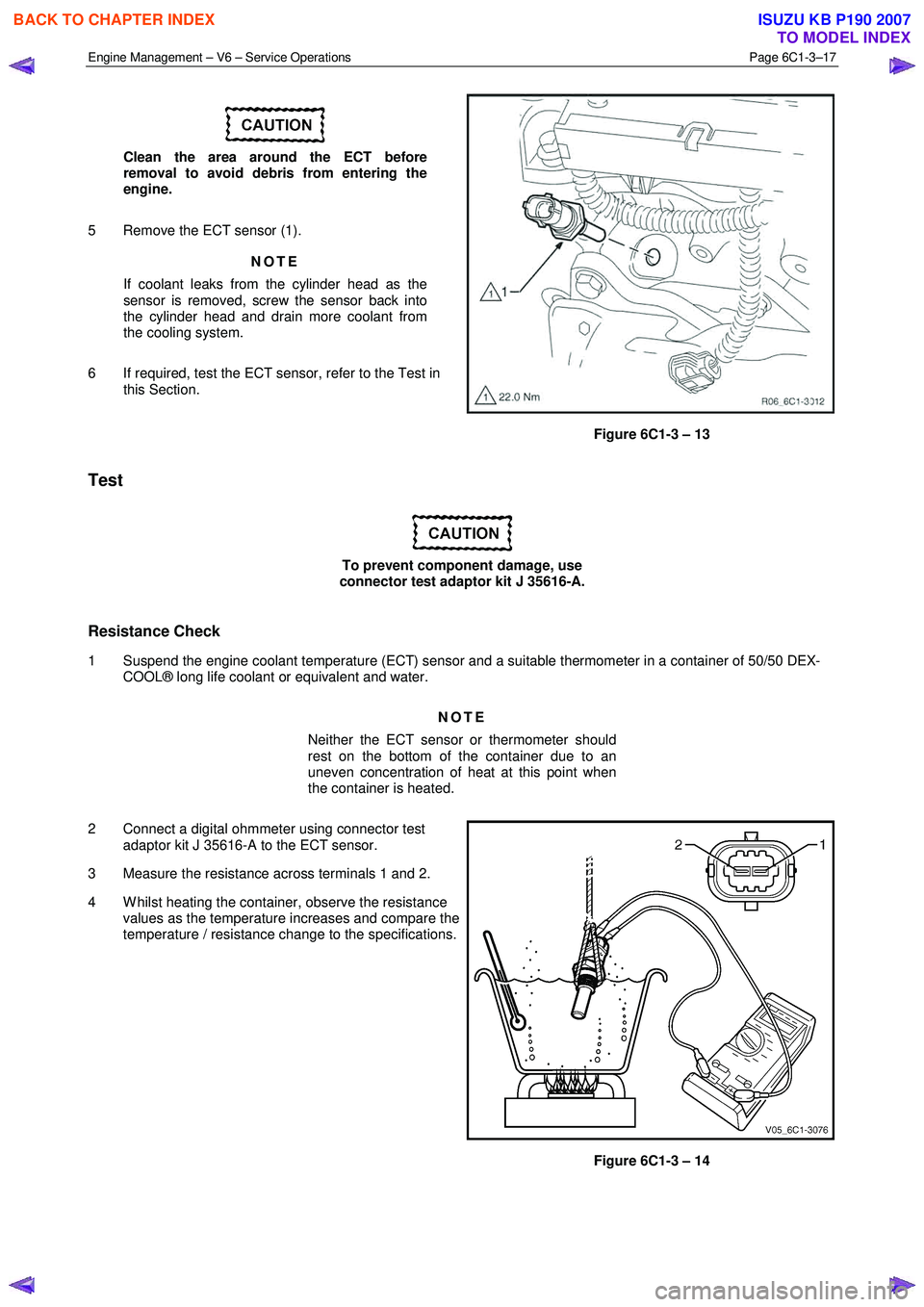
Clean the area around the ECT before
removal to avoid debris from entering the
engine.
5 Remove the ECT sensor (1). NOTE
If coolant leaks from the cylinder head as the
sensor is removed, screw the sensor back into
the cylinder head and drain more coolant from
the cooling system.
6 If required, test the ECT sensor, refer to the Test in this Section.
Figure 6C1-3 – 13
Test
To prevent component damage, use
connector test adaptor kit J 35616-A.
Resistance Check
1 Suspend the engine coolant temperature (ECT) sensor and a suitable thermometer in a container of 50/50 DEX- COOL® long life coolant or equivalent and water.
NOTE
Neither the ECT sensor or thermometer should
rest on the bottom of the container due to an
uneven concentration of heat at this point when
the container is heated.
2 Connect a digital ohmmeter using connector test adaptor kit J 35616-A to the ECT sensor.
3 Measure the resistance across terminals 1 and 2.
4 W hilst heating the container, observe the resistance values as the temperature increases and compare the
temperature / resistance change to the specifications.
Figure 6C1-3 – 14
BACK TO CHAPTER INDEX
TO MODEL INDEX
ISUZU KB P190 2007
Page 3542 of 6020
Engine Management – V6 – Service Operations Page 6C1-3–18
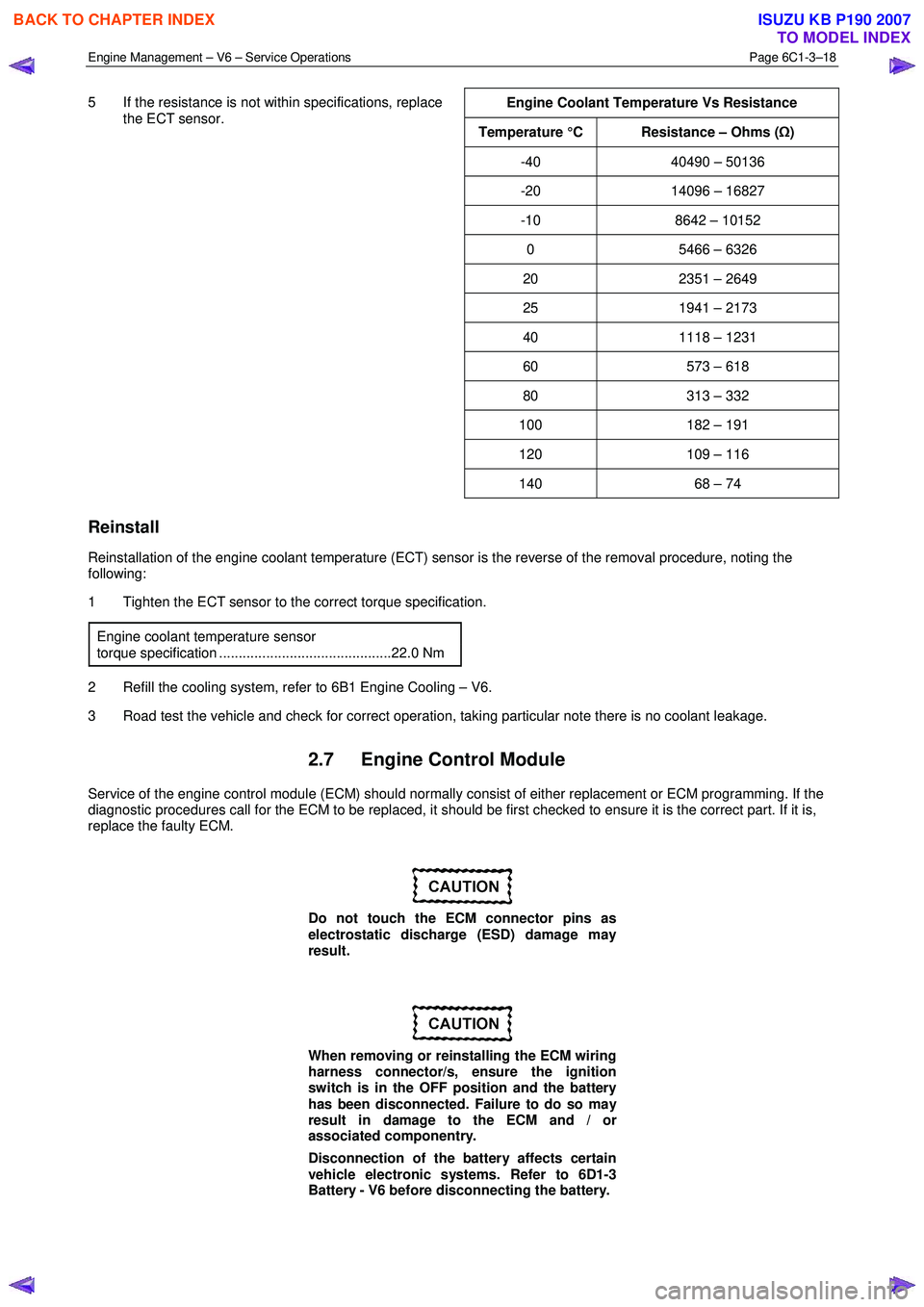
5 If the resistance is not within specifications, replace
the ECT sensor.
Engine Coolant Temperature Vs Resistance
Temperature °C Resistance – Ohms (
Ω)
-40 40490 – 50136
-20 14096 – 16827
-10 8642 – 10152
0 5466 – 6326
20 2351 – 2649
25 1941 – 2173
40 1118 – 1231
60 573 – 618
80 313 – 332
100 182 – 191
120 109 – 116
140 68 – 74
Reinstall
Reinstallation of the engine coolant temperature (ECT) sensor is the reverse of the removal procedure, noting the
following:
1 Tighten the ECT sensor to the correct torque specification.
Engine coolant temperature sensor
torque specification ............................................22.0 Nm
2 Refill the cooling system, refer to 6B1 Engine Cooling – V6.
3 Road test the vehicle and check for correct operation, taking particular note there is no coolant leakage.
2.7 Engine Control Module
Service of the engine control module (ECM) should normally consist of either replacement or ECM programming. If the
diagnostic procedures call for the ECM to be replaced, it should be first checked to ensure it is the correct part. If it is,
replace the faulty ECM.
Do not touch the ECM connector pins as
electrostatic discharge (ESD) damage may
result.
When removing or reinstalling the ECM wiring
harness connector/s, ensure the ignition
switch is in the OFF position and the battery
has been disconnected. Failure to do so may
result in damage to the ECM and / or
associated componentry.
Disconnection of the battery affects certain
vehicle electronic systems. Refer to 6D1-3
Battery - V6 before disconnecting the battery.
BACK TO CHAPTER INDEX
TO MODEL INDEX
ISUZU KB P190 2007
Page 3581 of 6020
Engine Management – V6 – Service Operations Page 6C1-3–57
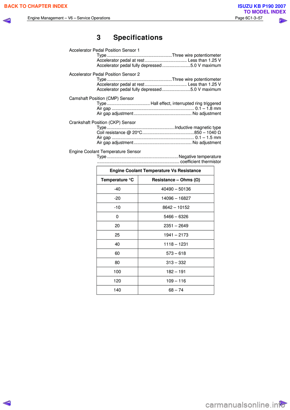
3 Specifications
Accelerator Pedal Position Sensor 1
Type .....................................................Three wire potentiometer
Accelerator pedal at rest .................................. Less than 1.25 V
Accelerator pedal fully depressed .......................5.0 V maximum
Accelerator Pedal Position Sensor 2
Type .....................................................Three wire potentiometer
Accelerator pedal at rest .................................. Less than 1.25 V
Accelerator pedal fully depressed .......................5.0 V maximum
Camshaft Position (CMP) Sensor
Type ................................... Hall effect, interrupted ring triggered
Air gap ................................................................... 0.1 – 1.8 mm
Air gap adjustment ............................................... No adjustment
Crankshaft Position (CKP) Sensor
Type ....................................................... Inductive magnetic type
Coil resistance @ 20°C .......................................... 850 – 1040 Ω
Air gap ................................................................... 0.1 – 1.5 mm
Air gap adjustment ............................................... No adjustment
Engine Coolant Temperature Sensor
Type .......................................................... Negative temperature
................................................................... coefficient thermistor
Engine Coolant Temperature Vs Resistance
Temperature °C Resistance – Ohms ( Ω)
-40 40490 – 50136
-20 14096 – 16827
-10 8642 – 10152
0 5466 – 6326
20 2351 – 2649
25 1941 – 2173
40 1118 – 1231
60 573 – 618
80 313 – 332
100 182 – 191
120 109 – 116
140 68 – 74
BACK TO CHAPTER INDEX
TO MODEL INDEX
ISUZU KB P190 2007
Page 3585 of 6020
Engine Management – V6 – Service Operations Page 6C1-3–61
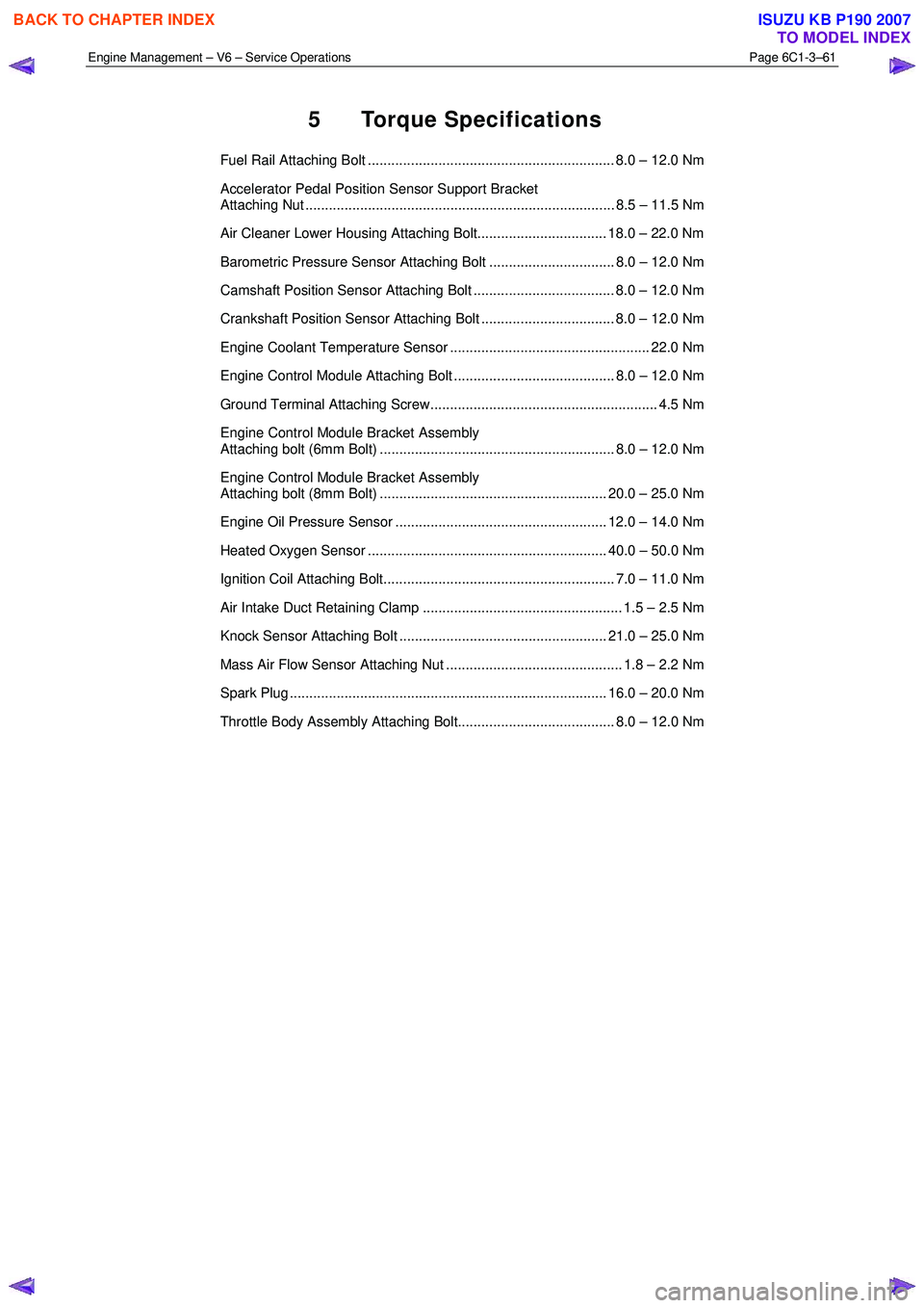
5 Torque Specifications
Fuel Rail Attaching Bolt ............................................................... 8.0 – 12.0 Nm
Accelerator Pedal Position Sensor Support Bracket
Attaching Nut ............................................................................... 8.5 – 11.5 Nm
Air Cleaner Lower Housing Attaching Bolt................................. 18.0 – 22.0 Nm
Barometric Pressure Sensor Attaching Bolt ................................ 8.0 – 12.0 Nm
Camshaft Position Sensor Attaching Bolt .................................... 8.0 – 12.0 Nm
Crankshaft Position Sensor Attaching Bolt .................................. 8.0 – 12.0 Nm
Engine Coolant Temperature Sensor ................................................... 22.0 Nm
Engine Control Module Attaching Bolt ......................................... 8.0 – 12.0 Nm
Ground Terminal Attaching Screw.......................................................... 4.5 Nm
Engine Control Module Bracket Assembly
Attaching bolt (6mm Bolt) ............................................................ 8.0 – 12.0 Nm
Engine Control Module Bracket Assembly
Attaching bolt (8mm Bolt) .......................................................... 20.0 – 25.0 Nm
Engine Oil Pressure Sensor ...................................................... 12.0 – 14.0 Nm
Heated Oxygen Sensor ............................................................. 40.0 – 50.0 Nm
Ignition Coil Attaching Bolt........................................................... 7.0 – 11.0 Nm
Air Intake Duct Retaining Clamp ................................................... 1.5 – 2.5 Nm
Knock Sensor Attaching Bolt ..................................................... 21.0 – 25.0 Nm
Mass Air Flow Sensor Attaching Nut ............................................. 1.8 – 2.2 Nm
Spark Plug ................................................................................. 16.0 – 20.0 Nm
Throttle Body Assembly Attaching Bolt........................................ 8.0 – 12.0 Nm
BACK TO CHAPTER INDEX
TO MODEL INDEX
ISUZU KB P190 2007
Page 3663 of 6020
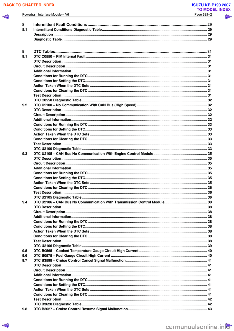
Powertrain Interface Module – V6 Page 6E1–2
8 Intermittent Fault Conditions ..............................................................................................................29
8.1 Intermittent Conditions Diagnostic Table ....................................................................................... ................... 29
Description ........................................................................................................................................................... 29
Diagnostic Table .................................................................................................................................................. 29
9 DTC Tables ............................................................................................................................................31
9.1 DTC C0550 – PIM Internal Fault ................................................................................................. ......................... 31
DTC Description ................................................................................................................................................... 31
Circuit Description ............................................................................................................................................... 31
Additional Information......................................................................................................... ................................ 31
Conditions for Running the DTC ................................................................................................. ....................... 31
Conditions for Setting the DTC........................................................................................................................... 31
Action Taken When the DTC Sets ................................................................................................. ..................... 31
Conditions for Clearing the DTC ........................................................................................................................ 31
Test Description ................................................................................................................................................... 31
DTC C0550 Diagnostic Table ..................................................................................................... ......................... 32
9.2 DTC U2100 – No Communication With CAN Bus (High Speed) ....................................................................... 32
DTC Description ................................................................................................................................................... 32
Circuit Description ............................................................................................................................................... 32
Additional Information......................................................................................................... ................................ 32
Conditions for Running the DTC ................................................................................................. ....................... 33
Conditions for Setting the DTC........................................................................................................................... 33
Action Taken When the DTC Sets ................................................................................................. ..................... 33
Conditions for Clearing the DTC ........................................................................................................................ 33
Test Description ................................................................................................................................................... 33
DTC U2100 Diagnostic Table ..................................................................................................... ......................... 33
9.3 DTC U2105 – CAN Bus No Communication With Engine Control Module ...................................................... 35
DTC Description ................................................................................................................................................... 35
Circuit Description ............................................................................................................................................... 35
Additional Information......................................................................................................... ................................ 35
Conditions for Running the DTC ................................................................................................. ....................... 35
Conditions for Setting the DTC........................................................................................................................... 35
Action Taken When the DTC Sets ................................................................................................. ..................... 35
Conditions for Clearing the DTC ........................................................................................................................ 36
Test Description ................................................................................................................................................... 36
DTC U2105 Diagnostic Table ..................................................................................................... ......................... 36
9.4 DTC U2106 – CAN Bus No Communication With Transmission Control Module........................................... 38
DTC Description ................................................................................................................................................... 38
Circuit Description ............................................................................................................................................... 38
Additional Information......................................................................................................... ................................ 38
Conditions for Running the DTC ................................................................................................. ....................... 38
Conditions for Setting the DTC........................................................................................................................... 38
Action Taken When the DTC Sets ................................................................................................. ..................... 38
Conditions for Clearing the DTC ........................................................................................................................ 38
Test Description ................................................................................................................................................... 38
DTC U2106 Diagnostic Table ..................................................................................................... ......................... 39
9.5 DTC B0565 – Coolant Temperature Gauge Circuit High Current ..................................................................... 40
9.6 DTC B0575 – Fuel Gauge Circuit High Current ................................................................................................. 40
9.7 DTC B3598 – Cruise Control Cancel Signal Malfunction........................................................................... ....... 41
DTC Description ................................................................................................................................................... 41
Circuit Description ............................................................................................................................................... 41
Additional Information......................................................................................................... ................................ 41
Conditions for Running the DTC ................................................................................................. ....................... 41
Conditions for Setting the DTC........................................................................................................................... 41
Action Taken When the DTC Sets ................................................................................................. ..................... 41
Conditions for Clearing the DTC ........................................................................................................................ 41
Test Description ................................................................................................................................................... 42
DTC B3628 Diagnostic Table ..................................................................................................... ......................... 42
9.8 DTC B3627 – Cruise Control Resume Signal Malfunction........................................................................... ..... 43
BACK TO CHAPTER INDEX
TO MODEL INDEX
ISUZU KB P190 2007
Page 3682 of 6020
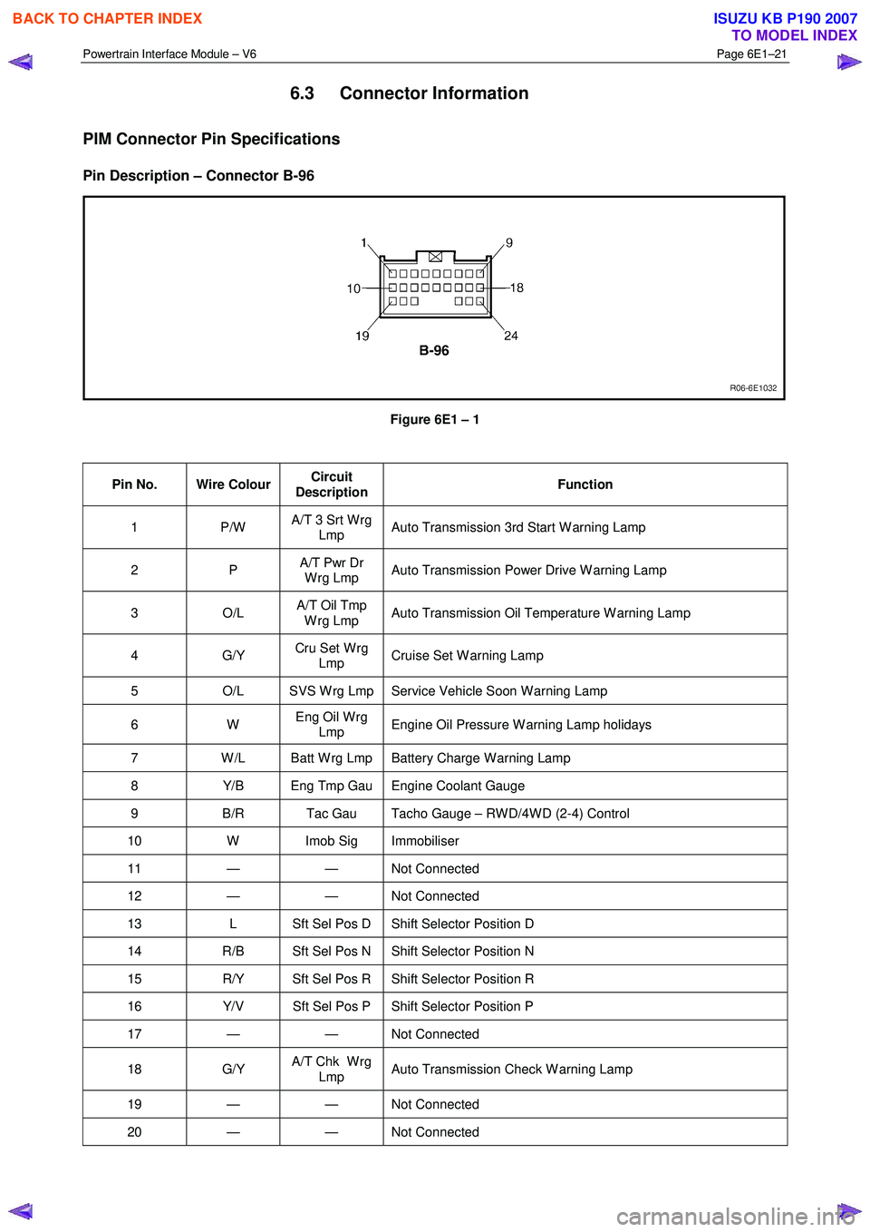
Powertrain Interface Module – V6 Page 6E1–21
6.3 Connector Information
PIM Connector Pin Specifications
Pin Description – Connector B-96
Figure 6E1 – 1
Pin No. Wire Colour Circuit
Description Function
1 P/W
A/T 3 Srt W rg
Lmp Auto Transmission 3rd Start W arning Lamp
2 P
A/T Pwr Dr
W rg Lmp Auto Transmission Power Drive W arning Lamp
3 O/L A/T Oil Tmp
W rg Lmp Auto Transmission Oil Temperature W arning Lamp
4 G/Y
Cru Set W rg
Lmp Cruise Set W arning Lamp
5
O/L SVS W rg Lmp Service Vehicle Soon W arning Lamp
6 W Eng Oil W rg
Lmp Engine Oil Pressure W arning Lamp holidays
7
W /L Batt W rg Lmp Battery Charge W arning Lamp
8 Y/B Eng Tmp Gau Engine Coolant Gauge
9 B/R Tac Gau Tacho Gauge – RW D/4W D (2-4) Control
10 W Imob Sig Immobiliser
11 — — Not Connected
12 — — Not Connected
13 L Sft Sel Pos D Shift Selector Position D
14 R/B Sft Sel Pos N Shift Selector Position N
15 R/Y Sft Sel Pos R Shift Selector Position R
16 Y/V Sft Sel Pos P Shift Selector Position P
17 — — Not Connected
18 G/Y A/T Chk W rg
Lmp Auto Transmission Check W arning Lamp
19 — — Not
Connected
20 — — Not Connected
BACK TO CHAPTER INDEX
TO MODEL INDEX
ISUZU KB P190 2007
Page 3701 of 6020
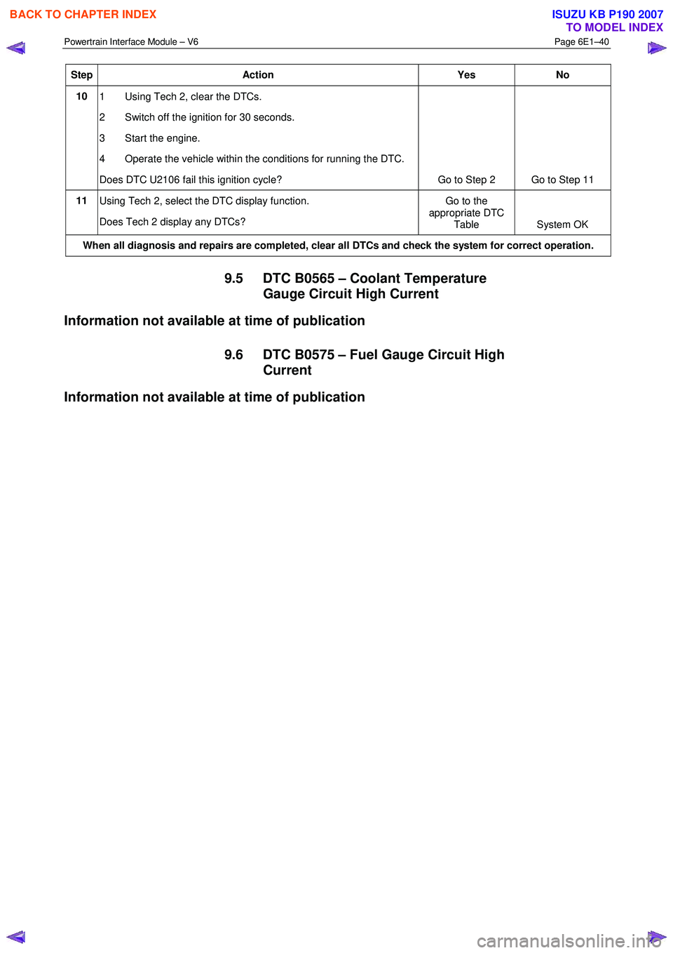
Powertrain Interface Module – V6 Page 6E1–40
Step Action Yes No
10
1 Using Tech 2, clear the DTCs.
2 Switch off the ignition for 30 seconds.
3 Start the engine.
4 Operate the vehicle within the conditions for running the DTC.
Does DTC U2106 fail this ignition cycle? Go to Step 2 Go to Step 11
11
Using Tech 2, select the DTC display function.
Does Tech 2 display any DTCs? Go to the
appropriate DTC Table System OK
When all diagnosis and repairs are completed, clear all DTCs and check the system for correct operation.
9.5 DTC B0565 – Coolant Temperature
Gauge Circuit High Current
Information not available at time of publication
9.6 DTC B0575 – Fuel Gauge Circuit High Current
Information not available at time of publication
BACK TO CHAPTER INDEX
TO MODEL INDEX
ISUZU KB P190 2007
Page 3742 of 6020
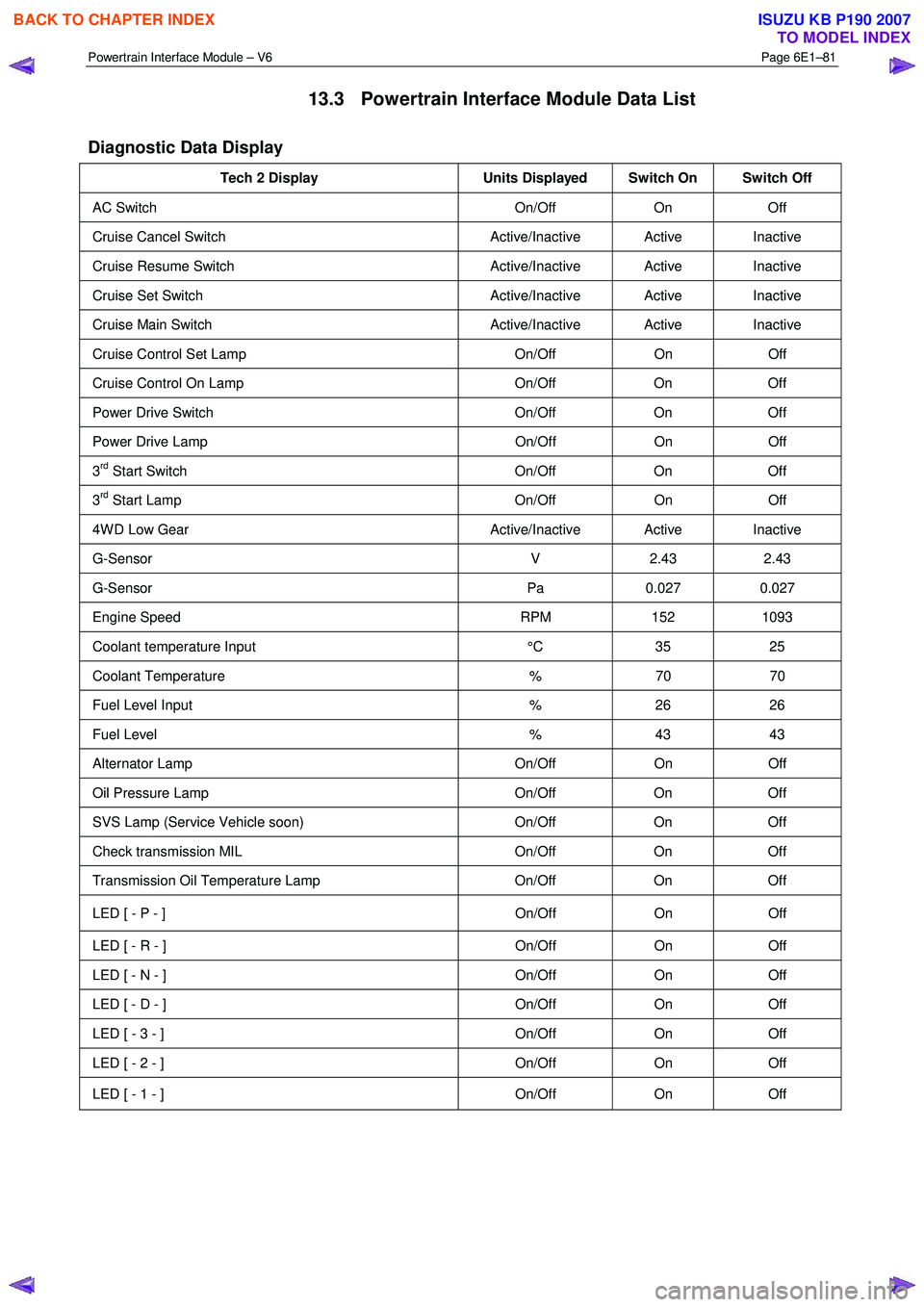
Powertrain Interface Module – V6 Page 6E1–81
13.3 Powertrain Interface Module Data List
Diagnostic Data Display
Tech 2 Display Units Displayed Switch On Switch Off
AC Switch On/Off On Off
Cruise Cancel Switch Active/Inactive Active Inactive
Cruise Resume Switch Active/Inactive Active Inactive
Cruise Set Switch Active/Inactive Active Inactive
Cruise Main Switch Active/Inactive Active Inactive
Cruise Control Set Lamp On/Off On Off
Cruise Control On Lamp On/Off On Off
Power Drive Switch On/Off On Off
Power Drive Lamp On/Off On Off
3rd Start Switch On/Off On Off
3rd Start Lamp On/Off On Off
4W D Low Gear Active/Inactive Active Inactive
G-Sensor V 2.43 2.43
G-Sensor Pa 0.027 0.027
Engine Speed RPM 152 1093
Coolant temperature Input °C 35 25
Coolant Temperature % 70 70
Fuel Level Input % 26 26
Fuel Level % 43 43
Alternator Lamp On/Off On Off
Oil Pressure Lamp On/Off On Off
SVS Lamp (Service Vehicle soon) On/Off On Off
Check transmission MIL On/Off On Off
Transmission Oil Temperature Lamp On/Off On Off
LED [ - P - ] On/Off On Off
LED [ - R - ] On/Off On Off
LED [ - N - ] On/Off On Off
LED [ - D - ] On/Off On Off
LED [ - 3 - ] On/Off On Off
LED [ - 2 - ] On/Off On Off
LED [ - 1 - ] On/Off On Off
BACK TO CHAPTER INDEX
TO MODEL INDEX
ISUZU KB P190 2007