2007 ISUZU KB P190 coolant temperature
[x] Cancel search: coolant temperaturePage 2224 of 6020
6E–54 ENGINE DRIVEABILITY AND EMISSIONS
GENERAL DESCRIPTION FOR ELECTRIC
IGNITION SYSTEM
The engine use two ignition coils, one per two cylinders.
A two wire connector provides a battery voltage primary
supply through the ignition fuse.
The ignition control spark timing is the ECM’s method of
controlling the spark advance and the ignition dwell.
The ignition control spark advance and the ignition dwell
are calculated by the ECM using the following inputs.
• Engine speed
• Crankshaft position (CKP) sensor
• Engine coolant temperature (ECT) sensor
• Throttle position sensor
• Vehicle speed sensor
• ECM and ignition system supply voltage
Ignition coil works to generate only the secondary
voltage be receiving the primary voltage from ECM.
The primary voltage is generated at the coil driver
located in the ECM. The coil driver generate the primary
voltage based on the crankshaft position signal. In
accordance with the crankshaft position signal, ignition
coil driver determines the adequate ignition timing and
also cylinder number to ignite.
Ignition timing is determined the coolant temperature,
intake air temperature, engine speed, engine load,
knock sensor signal, etc.
Spark Plug
Although worn or dirty spark plugs may give satisfactory
operation at idling speed, they frequently fail at higher
engine speeds. Faulty spark plugs may cause poor fuel
economy, power loss, loss of speed, hard starting and
generally poor engine performance. Follow the
scheduled maintenance service recommendations to
ensure satisfactory spark plug performance. Refer to
Maintenance and Lubrication .
Normal spark plug operation will result in brown to
grayish-tan deposits appearing on the insulator portion
of the spark plug. A small amount of red-brown, yellow,
and white powdery material may also be present on the
insulator tip around the center electrode. These
deposits are normal combustion by-products of fuels
and lubricating oils with additives. Some electrode wear
will also occur. Engines which are not running properly
are often referred to as “misfiring.” This means the
ignition spark is not igniting the air/fuel mixture at the
proper time. While other ignition and fuel system causes
must also be considered, possible causes include
ignition system conditions which allow the spark voltage
to reach ground in some other manner than by jumping
across the air gap at the tip of the spark plug, leaving
the air/fuel mixture unburned. Misfiring may also occur
when the tip of the spark plug becomes overheated and
ignites the mixture before the spark jumps. This is
referred to as “pre-ignition.”
Spark plugs may also misfire due to fouling, excessive
gap, or a cracked or broken insulator. If misfiring occurs before the recommended replacement interval, locate
and correct the cause.
Carbon fouling of the spark plug is indicated by dry,
black carbon (soot) deposits on the portion of the spark
plug in the cylinder. Excessive idling and slow speeds
under light engine loads can keep the spark plug
temperatures so low that these deposits are not burned
off. Very rich fuel mixtures or poor ignition system output
may also be the cause. Refer to DTC P1167.
Oil fouling of the spark plug is indicated by wet oily
deposits on the portion of the spark plug in the cylinder,
usually with little electrode wear. This may be caused by
oil during break-in of new or newly overhauled engines.
Deposit fouling of the spark plug occurs when the
normal red-brown, yellow or white deposits of
combustion by-products become sufficient to cause
misfiring. In some cases, these deposits may melt and
form a shiny glaze on the insulator around the center
electrode. If the fouling is found in only one or two
cylinders, valve stem clearances or intake valve seals
may be allowing excess lubricating oil to enter the
cylinder, particularly if the deposits are heavier on the
side of the spark plug facing the intake valve.
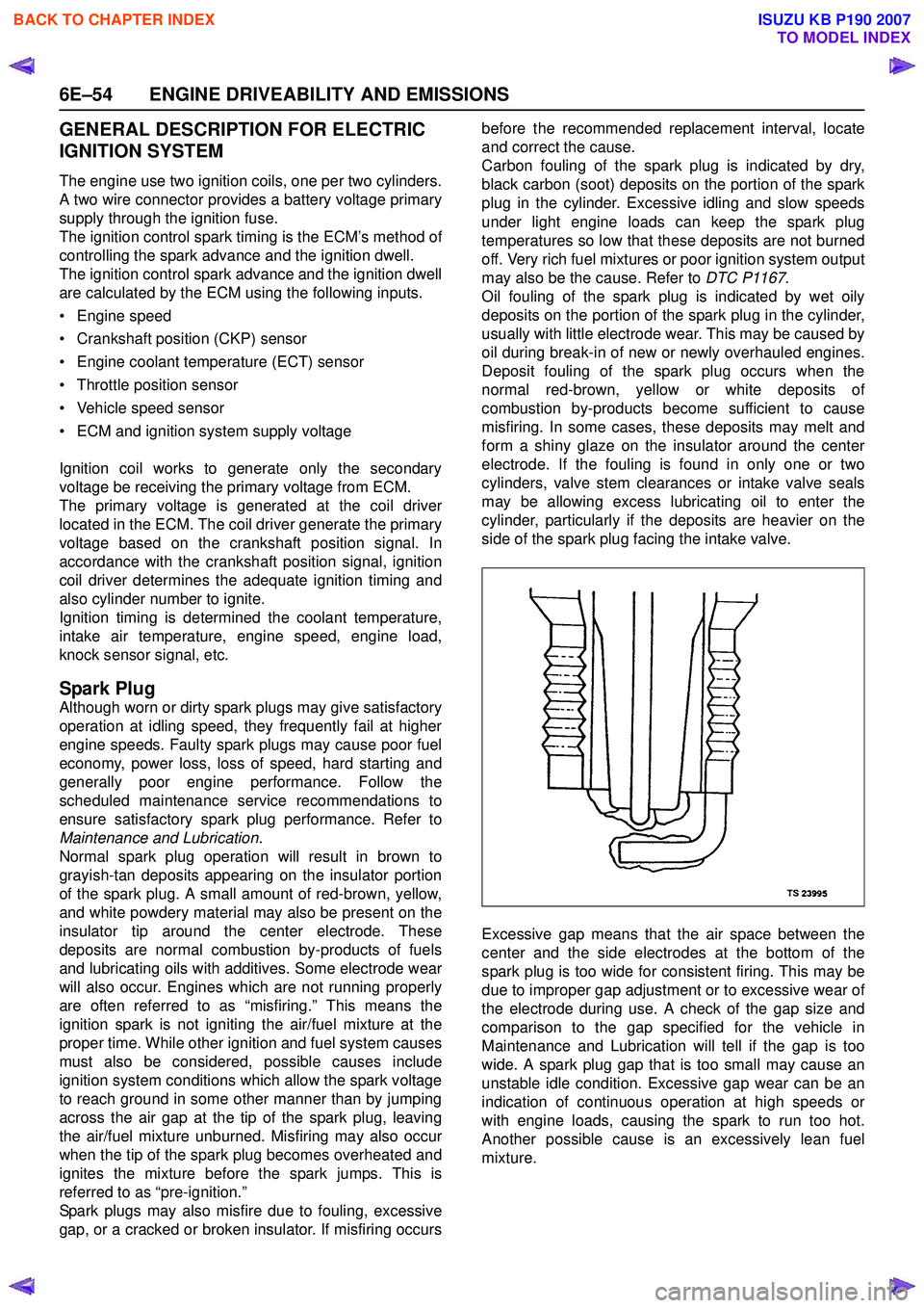
Excessive gap means that the air space between the
center and the side electrodes at the bottom of the
spark plug is too wide for consistent firing. This may be
due to improper gap adjustment or to excessive wear of
the electrode during use. A check of the gap size and
comparison to the gap specified for the vehicle in
Maintenance and Lubrication will tell if the gap is too
wide. A spark plug gap that is too small may cause an
unstable idle condition. Excessive gap wear can be an
indication of continuous operation at high speeds or
with engine loads, causing the spark to run too hot.
Another possible cause is an excessively lean fuel
mixture.
BACK TO CHAPTER INDEX
TO MODEL INDEX
ISUZU KB P190 2007
Page 2227 of 6020
ENGINE DRIVEABILITY AND EMISSIONS 6E–57
GENERAL DESCRIPTION FOR
EVAPORATIVE EMISSION SYSTEM
EVAP Emission Control System Purpose
The basic evaporative emission control system used on
the charcoal canister storage method. The method
transfers fuel vapor from the fuel tank to an activated
carbon (charcoal) storage devise to hold the vapors
when the vehicle is not operating.
The canister is located on the rear axle housing by the
frame cross-member.
When the engine is running, the fuel vapor is purged
from the carbon element by intake air flow and
consumed in the normal combustion process.
EVAP Emission Control System Operation
The EVAP canister purge is controlled by a solenoid
valve that allows the manifold vacuum to purge the
canister. The engine control module (ECM) supplies a
ground to energize the solenoid valve (purge on). The
EVAP purge solenoid control is pulse-width modulated
(PWM) (turned on and off several times a second). The
duty cycle (pulse width) is determined by engine
operating conditions including load, throttle position,
coolant temperature and ambient temperature. The duty
cycle is calculated by the ECM. the output is
commanded when the appropriate conditions have
been met. These conditions are:
• The engine is fully warmed up.
• The engine has been running for a specified time.
• The IAT reading is above 10°C (50°F).
• Purge/Vacuum Hoses. Made of rubber compounds, these hoses route the gasoline fumes from their
sources to the canister and from the canister to the
intake air flow.
• EVAP Canister. Mounted on a bracket ahead of the fuel tank, the canister stores fuel vapors until the
ECM determined that engine conditions are right for
them to be removed and burned.
Poor idle, stalling and Poor driveability can be caused
by:
• A malfunctioning purge solenoid.
• A damaged canister.
• Hoses that are split, cracked, or not connected properly.
System Fault Detection
The EVAP leak detection strategy is based on applying
vacuum to the EVAP system and monitoring vacuum
decay. At an appropriate time, the EVAP purge solenoid
is turned “ON,” allowing the engine vacuum to draw a
small vacuum on the entire evaporative emission
system.
After the desired vacuum level has been achieved, the
EVAP purge solenoid is turned “OFF,” sealing the
system. A leak is detected by monitoring for a decrease
in vacuum level over a given time period, all other
variables remaining constant.
If the desired vacuum level cannot be achieved in the
test described above, a large leak or a faulty EVAP
purge control solenoid valve is indicated.
Leaks can be caused by the following conditions:
• Missing or faulty fuel cap
• Disconnected, damaged, pinched, or blocked EVAP purge line
• Disconnected, damaged, pinched, or blocked fuel tank vapor line
• Disconnected or faulty EVAP purge control solenoid valve
• Open ignition feed circuit to the purge solenoid
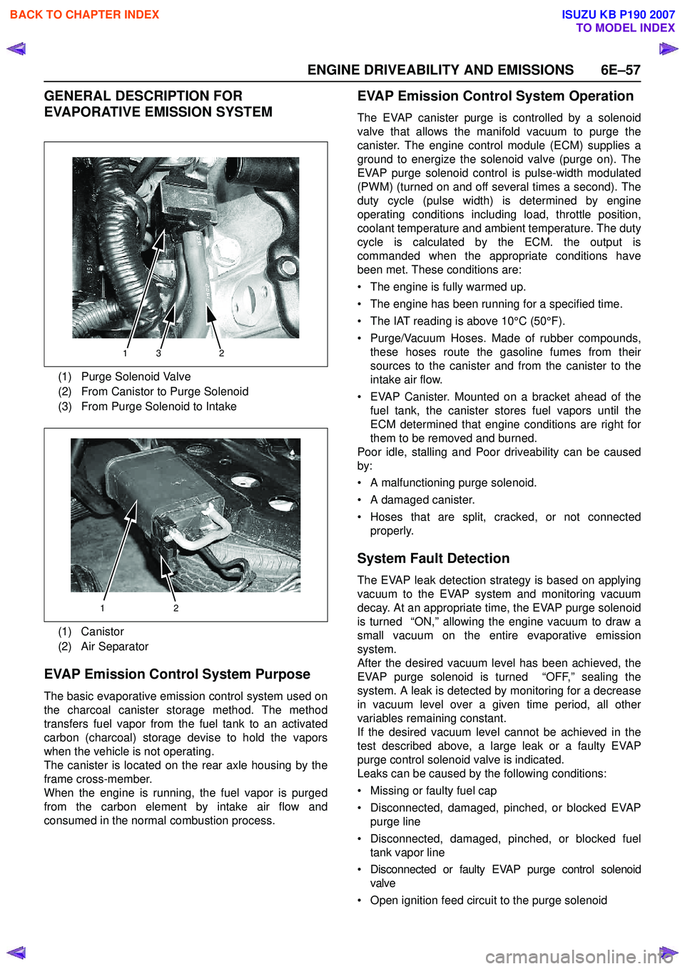
(1) Purge Solenoid Valve
(2) From Canistor to Purge Solenoid
(3) From Purge Solenoid to Intake
(1) Canistor
(2) Air Separator
132
12
BACK TO CHAPTER INDEX
TO MODEL INDEX
ISUZU KB P190 2007
Page 2228 of 6020
6E–58 ENGINE DRIVEABILITY AND EMISSIONS
• Damaged EVAP canister
• Leaking fuel sender assembly O-ring
• Leaking fuel tank or fuel filler neck
The ECM supplies a ground to energize the purge
control solenoid valve (purge “ON” ). The EVAP purge
control is turned “ON” and “OFF,” several times a
second. The duty cycle (pulse width) is determined by
engine operating conditions including load, throttle
position, coolant temperature and ambient temperature.
The duty cycle is calculated by the ECM and the output
is commanded when the appropriate conditions have
been met.
The system checks for conditions that cause the EVAP
system to purge continuously by commanding the EVAP
purge solenoid “OFF”, EVAP purge solenoid duty ratio
“0%”. If fuel tank vacuum level increases during the test,
a continuous purge flow condition is indicated. This can
be caused by the following conditions:
• EVAP purge solenoid leaking
• EVAP purge and engine vacuum lines switched at the EVAP purge control solenoid valve
• EVAP purge control solenoid valve driver circuit grounded
BACK TO CHAPTER INDEX
TO MODEL INDEX
ISUZU KB P190 2007
Page 2242 of 6020
6E–72 ENGINE DRIVEABILITY AND EMISSIONS
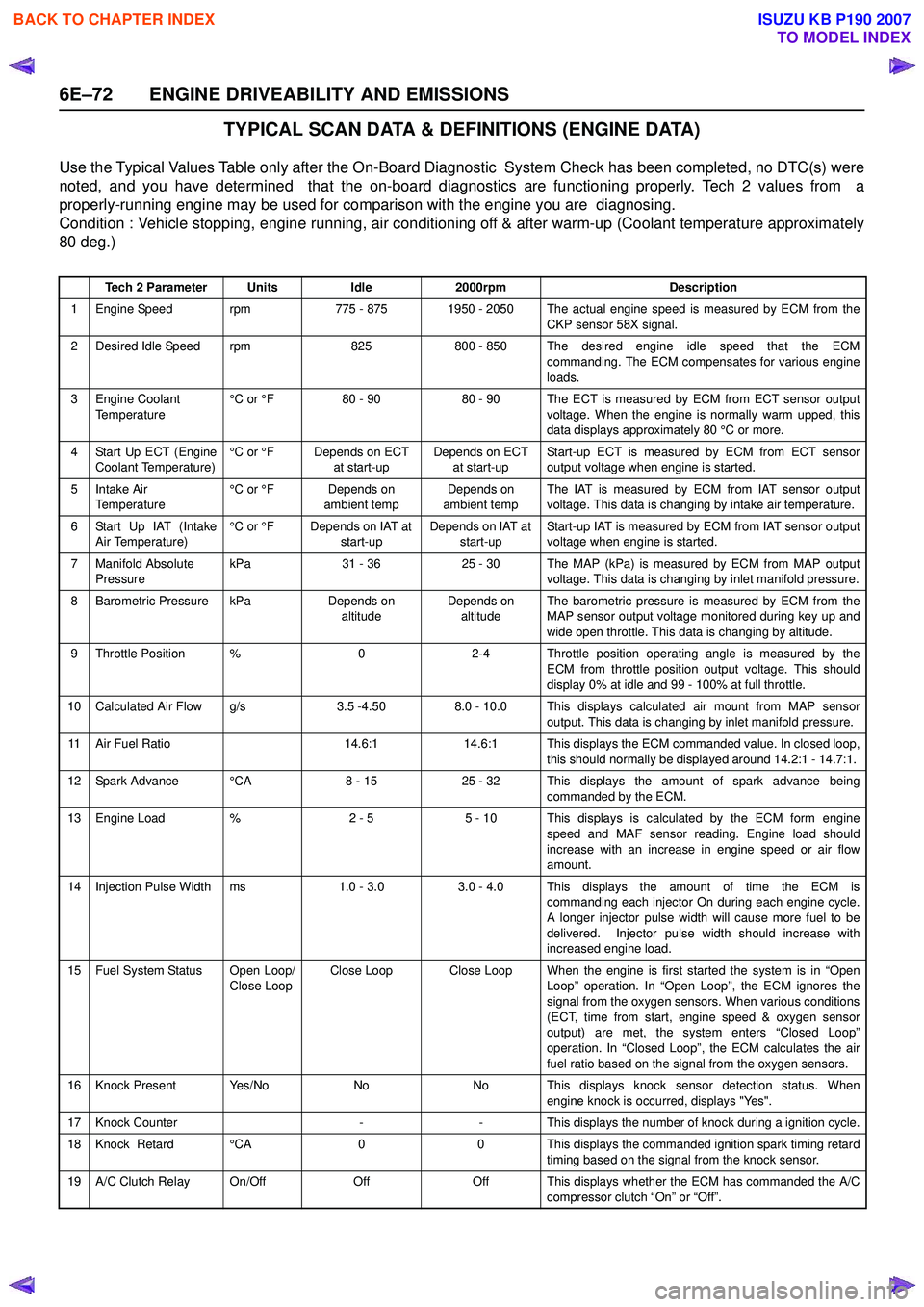
TYPICAL SCAN DATA & DEFINITIONS (ENGINE DATA)
Use the Typical Values Table only after the On-Board Diagnostic System Check has been completed, no DTC(s) were
noted, and you have determined that the on-board diagnostics are functioning properly. Tech 2 values from a
properly-running engine may be used for comparison with the engine you are diagnosing.
Condition : Vehicle stopping, engine running, air conditioning off & after warm-up (Coolant temperature approximately
80 deg.)
Tech 2 ParameterUnitsIdle2000rpmDescription
1 Engine Speed rpm775 - 8751950 - 2050 The actual engine speed is measured by ECM from the
CKP sensor 58X signal.
2 Desired Idle Speed rpm825800 - 850 The desired engine idle speed that the ECMcommanding. The ECM compensates for various engine
loads.
3 Engine Coolant Temperature °C or °F80 - 9080 - 90 The ECT is measured by ECM from ECT sensor output
voltage. When the engine is normally warm upped, this
data displays approximately 80 °C or more.
4 Start Up ECT (Engine Coolant Temperature) °C or °FDepends on ECT
at start-upDepends on ECT at start-up Start-up ECT is measured by ECM from ECT sensor
output voltage when engine is started.
5Intake Air
Temperature °C or °FDepends on
ambient tempDepends on
ambient temp The IAT is measured by ECM from IAT sensor output
voltage. This data is changing by intake air temperature.
6 Start Up IAT (Intake Air Temperature) °C or °FDepends on IAT at
start-upDepends on IAT at start-up Start-up IAT is measured by ECM from IAT sensor output
voltage when engine is started.
7 Manifold Absolute Pressure kPa31 - 3625 - 30The MAP (kPa) is measured by ECM from MAP output
voltage. This data is changing by inlet manifold pressure.
8 Barometric Pressure kPaDepends on altitudeDepends on altitude The barometric pressure is measured by ECM from the
MAP sensor output voltage monitored during key up and
wide open throttle. This data is changing by altitude.
9 Throttle Position %02-4 Throttle position operating angle is measured by the ECM from throttle position output voltage. This should
display 0% at idle and 99 - 100% at full throttle.
10 Calculated Air Flow g/s3.5 -4.508.0 - 10.0 This displays calculated air mount from MAP sensor output. This data is changing by inlet manifold pressure.
11 Air Fuel Ratio14.6:114.6:1 This displays the ECM commanded value. In closed loop,this should normally be displayed around 14.2:1 - 14.7:1.
12 Spark Advance °CA8 - 1525 - 32 This displays the amount of spark advance being commanded by the ECM.
13 Engine Load %2 - 55 - 10 This displays is calculated by the ECM form engine
speed and MAF sensor reading. Engine load should
increase with an increase in engine speed or air flow
amount.
14 Injection Pulse Width ms1.0 - 3.0 3.0 - 4.0 This displays the amount of time the ECM is commanding each injector On during each engine cycle.
A longer injector pulse width will cause more fuel to be
delivered. Injector pulse width should increase with
increased engine load.
15 Fuel System Status Open Loop/ Close LoopClose LoopClose Loop When the engine is first started the system is in “OpenLoop” operation. In “Open Loop”, the ECM ignores the
signal from the oxygen sensors. When various conditions
(ECT, time from start, engine speed & oxygen sensor
output) are met, the system enters “Closed Loop”
operation. In “Closed Loop”, the ECM calculates the air
fuel ratio based on the signal from the oxygen sensors.
16 Knock Present Yes/NoNoNo This displays knock sensor detection status. When engine knock is occurred, displays "Yes".
17 Knock Counter--This displays the number of knock during a ignition cycle.
18 Knock Retard °CA00 This displays the commanded ignition spark timing retard
timing based on the signal from the knock sensor.
19 A/C Clutch Relay On/OffOffOff This displays whether the ECM has commanded the A/C compressor clutch “On” or “Off”.
BACK TO CHAPTER INDEX
TO MODEL INDEX
ISUZU KB P190 2007
Page 2244 of 6020

6E–74 ENGINE DRIVEABILITY AND EMISSIONS
TYPICAL SCAN DATA & DEFINITIONS (O2 SENSOR DATA)
Use the Typical Values Table only after the On-Board Diagnostic System Check has been completed, no DTC(s) were
noted, and you have determined that the on-board diagnostics are functioning properly. Tech 2 values from a
properly-running engine may be used for comparison with the engine you are diagnosing.
Condition : Vehicle stopping, engine running, air conditioning off & after warm-up (Coolant temperature approximately
80 deg.)
Tech 2 ParameterUnitsIdle2000rpmDescription
1 Engine Speed rpm710 - 8751950 - 2050 The actual engine speed is measured by ECM from the
CKP sensor 58X signal.
2 Desired Idle Speed rpm825800 - 850 The desired engine idle speed that the ECMcommanding. The ECM compensates for various engine
loads.
3 Engine Coolant Temperature °C or °F80 - 9080 - 90 The ECT is measured by ECM from ECT sensor output
voltage. When the engine is normally warm upped, this
data displays approximately 80 °C or more.
4 Start Up ECT (Engine Coolant Temperature) °C or °FDepends on ECT
at start-upDepends on ECT at start-up Start-up ECT is measured by ECM from ECT sensor
output voltage when engine is started.
5Intake Air
Temperature °C or °FDepends on
ambient tempDepends on
ambient temp The IAT is measured by ECM from IAT sensor output
voltage. This data is changing by intake air temperature.
6 Start Up IAT (Intake Air Temperature) °C or °FDepends on IAT at
start-upDepends on IAT at start-up Start-up IAT is measured by ECM from IAT sensor output
voltage when engine is started.
7 Manifold Absolute Pressure kPa31 - 3625 - 30The MAP (kPa) is measured by ECM from MAP output
voltage. This data is changing by inlet manifold pressure.
8 Barometric Pressure kPaDepends on altitudeDepends on altitude The barometric pressure is measured by ECM from the
MAP sensor output voltage monitored during key up and
wide open throttle. This data is changing by altitude.
9 Throttle Position %02 - 4 Throttle position operating angle is measured by the ECM from throttle position output voltage. This should
display 0% at idle and 99 - 100% at full throttle.
10 Calculated Air Flow g/s3.5 -4.508.0 - 10.0 This displays intake air amount. The mass air flow is measured by ECM from the MAF sensor output voltage.
11 Air Fuel Ratio14.6:114.6:1 This displays the ECM commanded value. In closedloop, this should normally be displayed around 14.2:1 -
14.7:1.
12 Fuel System Status Open Loop/ Close LoopClose LoopClose Loop When the engine is first started the system is in “OpenLoop” operation. In “Open Loop”, the ECM ignores the
signal from the oxygen sensors. When various
conditions (ECT, time from start, engine speed & oxygen
sensor output) are met, the system enters “Closed Loop”
operation. In “Closed Loop”, the ECM calculates the air
fuel ratio based on the signal from the oxygen sensors.
13 Engine Load %2 - 55 - 10 This displays is calculated by the ECM form engine
speed and MAF sensor reading. Engine load should
increase with an increase in engine speed or air flow
amount.
14B1 O2 Sensor Ready
(Bank 1)Ye s / N oYe sYes This displays the status of the exhaust oxygen sensor. This display will indicate “Yes” when the ECM detects a
fluctuating oxygen sensor output voltage sufficient to
allow closed loop operation. This will not occur unless
the oxygen sensor is warmed up.
15B1S1 Status
(Bank 1 Sensor 1)Rich / LeanRich / LeanRich / Lean This displays dependent on the exhaust oxygen sensor output voltage. Should fluctuate constantly “Rich” and
“Lean” in closed loop.
16 Fuel Trim Learned Yes/NoYe sYes When conditions are appropriate for enabling long term fuel trim corrections, fuel trim learn will display “Yes”.
This indicates that the long term fuel trim is responding
to the short term fuel trim. If the fuel trim lean displays
“No”, then long term fuel trim will not respond to changes
in short term fuel trim.
BACK TO CHAPTER INDEX
TO MODEL INDEX
ISUZU KB P190 2007
Page 2246 of 6020
6E–76 ENGINE DRIVEABILITY AND EMISSIONS
MISCELLANEOUS TEST
The state of each circuit can be tested by using
miscellaneous test menus. Especially when DTC
cannot be detected, a faulty circuit can be diagnosed by
testing each circuit by means of these menus.
Even DTC has been detected, the circuit tests using
these menus could help discriminate between a
mechanical trouble and an electrical trouble.
Connect Tech 2 and select “Powertrain”, “2.XL L4
HV240” & “Miscellaneous Test”.
F0: Lamps
F0: Malfunction Indicator Lamp
When the Tech 2 is operated, “Malfunction Indicator
Lamp (Check Engine Lamp)” is turned on or off.
The circuit is normal if the “Malfunction Indicator Lamp
(Check Engine Lamp)” in the instrument panel is turned
on or off in accordance with this operation.
F1: Relays
F0: Fuel Pump Relay
When the Tech 2 is operated, fuel pump relay signal
turns ON or OFF.
The circuit is normal if fuel pump sound is generated in
accordance with this operation when key switch is
turned ON.
F1: A/C Clutch Relay
When the Tech 2 is operated, A/C clutch relay signal
turns ON or OFF.
The circuit is normal if A/C compressor clutch is
energized in accordance with this operation when the
engine is running.
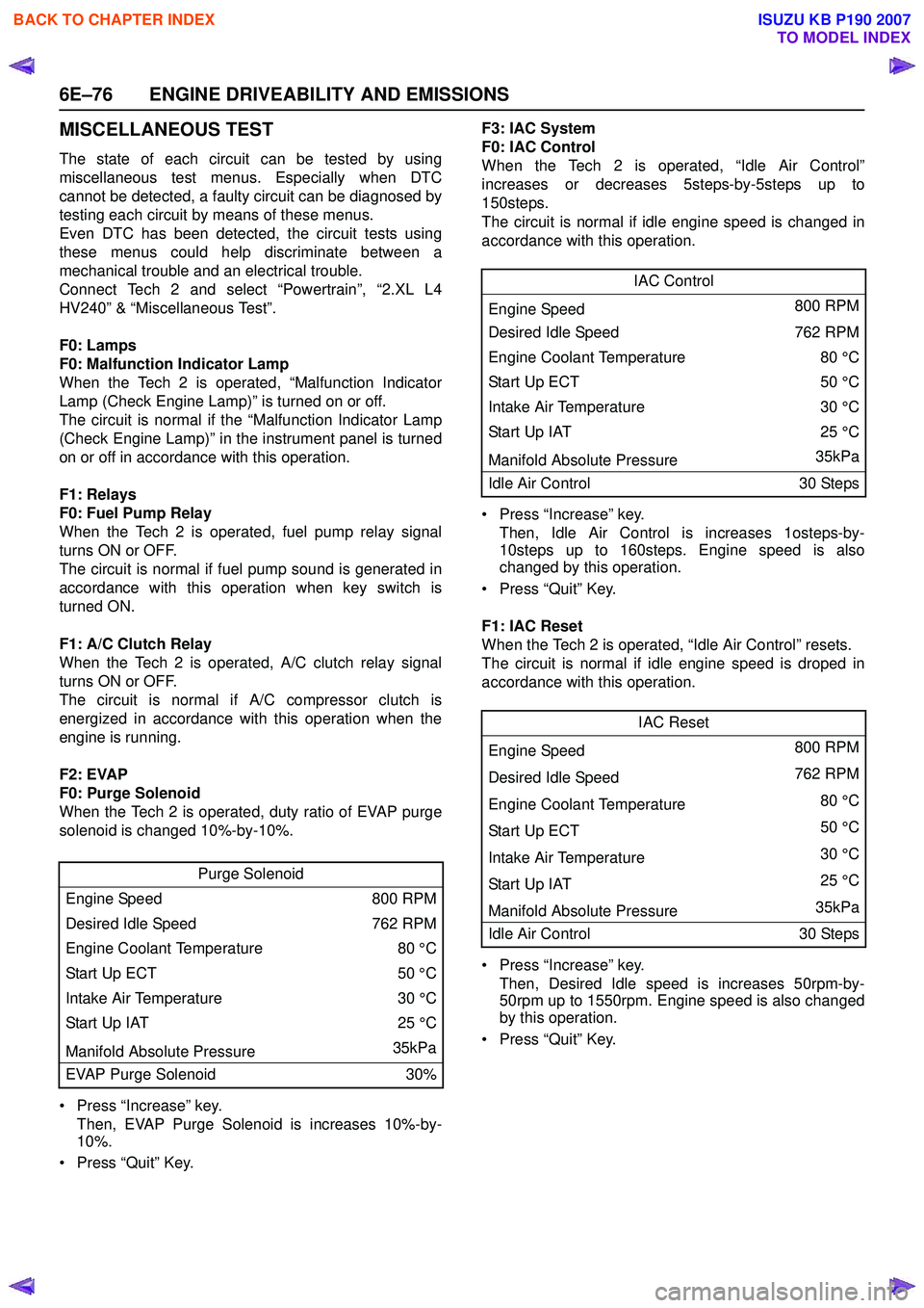
F2: EVAP
F0: Purge Solenoid
When the Tech 2 is operated, duty ratio of EVAP purge
solenoid is changed 10%-by-10%.
• Press “Increase” key. Then, EVAP Purge Solenoid is increases 10%-by-
10%.
• Press “Quit” Key. F3: IAC System
F0: IAC Control
When the Tech 2 is operated, “Idle Air Control”
increases or decreases 5steps-by-5steps up to
150steps.
The circuit is normal if idle engine speed is changed in
accordance with this operation.
• Press “Increase” key. Then, Idle Air Control is increases 1osteps-by-
10steps up to 160steps. Engine speed is also
changed by this operation.
• Press “Quit” Key.
F1: IAC Reset
When the Tech 2 is operated, “Idle Air Control” resets.
The circuit is normal if idle engine speed is droped in
accordance with this operation.
• Press “Increase” key. Then, Desired Idle speed is increases 50rpm-by-
50rpm up to 1550rpm. Engine speed is also changed
by this operation.
• Press “Quit” Key.
Purge Solenoid
Engine Speed 800 RPM
Desired Idle Speed 762 RPM
Engine Coolant Temperature 80 °C
Start Up ECT 50 °C
Intake Air Temperature 30 °C
Start Up IAT 25 °C
Manifold Absolute Pressure 35kPa
EVAP Purge Solenoid 30%
IAC Control
Engine Speed 800 RPM
Desired Idle Speed 762 RPM
Engine Coolant Temperature 80 °C
Sta rt U p E C T 50 °C
Intake Air Temperature 30 °C
Start Up IAT25 °C
Manifold Absolute Pressure 35kPa
Idle Air Control 30 Steps
IAC Reset
Engine Speed 800 RPM
Desired Idle Speed 762 RPM
Engine Coolant Temperature 80 °C
Sta rt U p E C T 50 °C
Intake Air Temperature 30 °C
Start Up IAT 25 °C
Manifold Absolute Pressure 35kPa
Idle Air Control 30 Steps
BACK TO CHAPTER INDEX
TO MODEL INDEX
ISUZU KB P190 2007
Page 2247 of 6020
ENGINE DRIVEABILITY AND EMISSIONS 6E–77
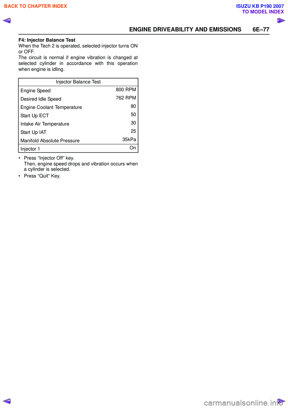
F4: Injector Balance Test
When the Tech 2 is operated, selected injector turns ON
or OFF.
The circuit is normal if engine vibration is changed at
selected cylinder in accordance with this operation
when engine is idling.
• Press “Injector Off” key. Then, engine speed drops and vibration occurs when
a cylinder is selected.
• Press “Quit” Key. Injector Balance Test
Engine Speed 800 RPM
Desired Idle Speed 762 RPM
Engine Coolant Temperature 80
Start Up ECT 50
Intake Air Temperature 30
Start Up IAT 25
Manifold Absolute Pressure 35kPa
Injector 1 On
BACK TO CHAPTER INDEX
TO MODEL INDEX
ISUZU KB P190 2007
Page 2270 of 6020
6E–100 ENGINE DRIVEABILITY AND EMISSIONS
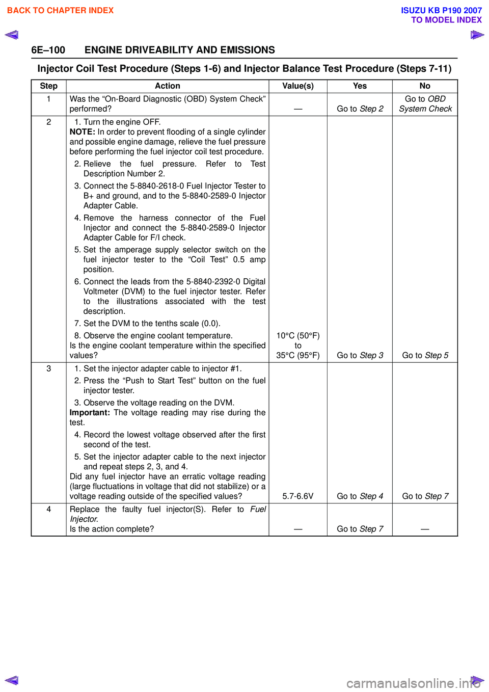
Injector Coil Test Procedure (Steps 1-6) and Injector Balance Test Procedure (Steps 7-11)
StepAction Value(s) Yes No
1 Was the “On-Board Diagnostic (OBD) System Check” performed? — Go to Step 2Go to
OBD
System Check
2 1. Turn the engine OFF. NOTE: In order to prevent flooding of a single cylinder
and possible engine damage, relieve the fuel pressure
before performing the fuel injector coil test procedure.
2. Relieve the fuel pressure. Refer to Test Description Number 2.
3. Connect the 5-8840-2618-0 Fuel Injector Tester to B+ and ground, and to the 5-8840-2589-0 Injector
Adapter Cable.
4. Remove the harness connector of the Fuel Injector and connect the 5-8840-2589-0 Injector
Adapter Cable for F/I check.
5. Set the amperage supply selector switch on the fuel injector tester to the “Coil Test” 0.5 amp
position.
6. Connect the leads from the 5-8840-2392-0 Digital Voltmeter (DVM) to the fuel injector tester. Refer
to the illustrations associated with the test
description.
7. Set the DVM to the tenths scale (0.0).
8. Observe the engine coolant temperature.
Is the engine coolant temperature within the specified
values? 10°C (50°F)
to
35°C (95°F) Go to Step 3Go to Step 5
3 1. Set the injector adapter cable to injector #1. 2. Press the “Push to Start Test” button on the fuelinjector tester.
3. Observe the voltage reading on the DVM.
Important: The voltage reading may rise during the
test.
4. Record the lowest voltage observed after the first second of the test.
5. Set the injector adapter cable to the next injector and repeat steps 2, 3, and 4.
Did any fuel injector have an erratic voltage reading
(large fluctuations in voltage that did not stabilize) or a
voltage reading outside of the specified values? 5.7-6.6V Go to Step 4Go to Step 7
4 Replace the faulty fuel injector(S). Refer to Fuel
Injector .
Is the action complete? — Go to Step 7—
BACK TO CHAPTER INDEX
TO MODEL INDEX
ISUZU KB P190 2007