2007 ISUZU KB P190 coolant temperature
[x] Cancel search: coolant temperaturePage 1971 of 6020
6E-354 ENGINE CONTROL SYSTEM (4JK1/4JJ1)
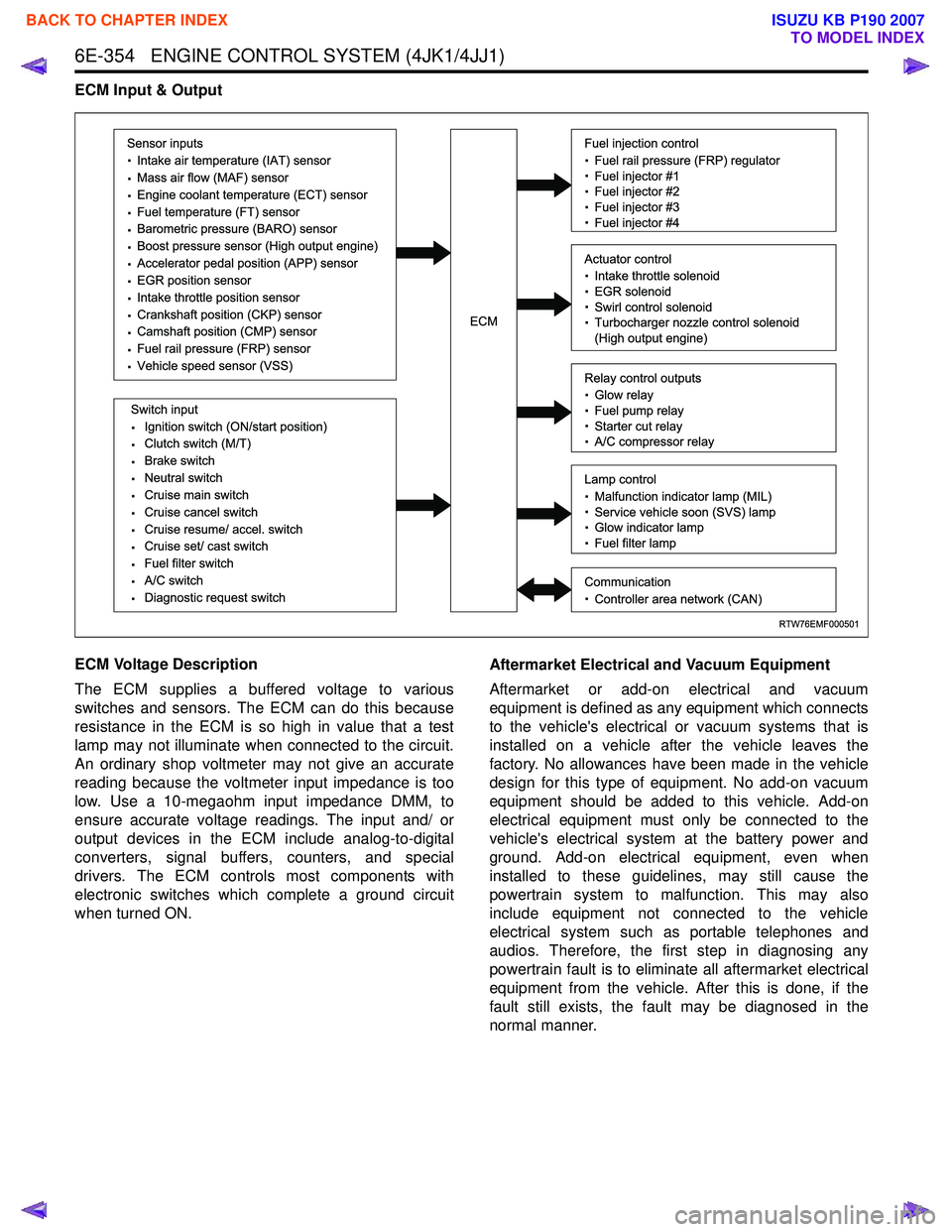
ECM Input & Output
ECM Voltage Description
The ECM supplies a buffered voltage to various
switches and sensors. The ECM can do this because
resistance in the ECM is so high in value that a test
lamp may not illuminate when connected to the circuit.
An ordinary shop voltmeter may not give an accurate
reading because the voltmeter input impedance is too
low. Use a 10-megaohm input impedance DMM, to
ensure accurate voltage readings. The input and/ or
output devices in the ECM include analog-to-digital
converters, signal buffers, counters, and special
drivers. The ECM controls most components with
electronic switches which complete a ground circuit
when turned ON. Aftermarket Electrical and Vacuum Equipment
Aftermarket or add-on electrical and vacuum
equipment is defined as any equipment which connects
to the vehicle's electrical or vacuum systems that is
installed on a vehicle after the vehicle leaves the
factory. No allowances have been made in the vehicle
design for this type of equipment. No add-on vacuum
equipment should be added to this vehicle. Add-on
electrical equipment must only be connected to the
vehicle's electrical system at the battery power and
ground. Add-on electrical equipment, even when
installed to these guidelines, may still cause the
powertrain system to malfunction. This may also
include equipment not connected to the vehicle
electrical system such as portable telephones and
audios. Therefore, the first step in diagnosing any
powertrain fault is to eliminate all aftermarket electrical
equipment from the vehicle. After this is done, if the
fault still exists, the fault may be diagnosed in the
normal manner.
RTW76EMF000501
Sensor inputs
· Intake air temperature (IAT) sensor
· Mass air flow (MAF) sensor
· Engine coolant temperature (ECT) sensor
· Fuel temperature (FT) sensor
· Barometric pressure (BARO) sensor
· Boost pressure sensor (High output engine)
· Accelerator pedal position (APP) sensor
· EGR position sensor
· Intake throttle position sensor
· Crankshaft position (CKP) sensor
· Camshaft position (CMP) sensor
· Fuel rail pressure (FRP) sensor
· Vehicle speed sensor (VSS)
Switch input
· Ignition switch (ON/start position)
· Clutch switch (M/T)
· Brake switch
· Neutral switch
· Cruise main switch
· Cruise cancel switch
· Cruise resume/ accel. switch
· Cruise set/ cast switch
· Fuel filter switch
· A/C switch
· Diagnostic request switch
Fuel injection control
· Fuel rail pressure (FRP) regulator
· Fuel injector #1
· Fuel injector #2
· Fuel injector #3
· Fuel injector #4
Relay control outputs
· Glow relay
· Fuel pump relay
· Starter cut relay
· A/C compressor relay
Lamp control
· Malfunction indicator lamp (MIL)
· Service vehicle soon (SVS) lamp
· Glow indicator lamp
· Fuel filter lamp
Communication
· Controller area network (CAN)
Actuator control
· Intake throttle solenoid
· EGR solenoid
· Swirl control solenoid
· Turbocharger nozzle control solenoid
(High output engine)ECM
BACK TO CHAPTER INDEX
TO MODEL INDEX
ISUZU KB P190 2007
Page 1975 of 6020
6E-358 ENGINE CONTROL SYSTEM (4JK1/4JJ1)
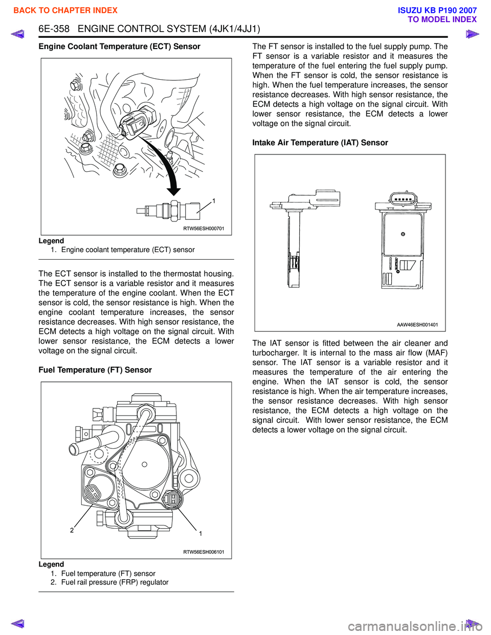
Engine Coolant Temperature (ECT) Sensor
Legend1. Engine coolant temperature (ECT) sensor
The ECT sensor is installed to the thermostat housing.
The ECT sensor is a variable resistor and it measures
the temperature of the engine coolant. When the ECT
sensor is cold, the sensor resistance is high. When the
engine coolant temperature increases, the sensor
resistance decreases. With high sensor resistance, the
ECM detects a high voltage on the signal circuit. With
lower sensor resistance, the ECM detects a lower
voltage on the signal circuit.
Fuel Temperature (FT) Sensor
Legend 1. Fuel temperature (FT) sensor
2. Fuel rail pressure (FRP) regulator
The FT sensor is installed to the fuel supply pump. The
FT sensor is a variable resistor and it measures the
temperature of the fuel entering the fuel supply pump.
When the FT sensor is cold, the sensor resistance is
high. When the fuel temperature increases, the sensor
resistance decreases. With high sensor resistance, the
ECM detects a high voltage on the signal circuit. With
lower sensor resistance, the ECM detects a lower
voltage on the signal circuit.
Intake Air Temperature (IAT) Sensor
The IAT sensor is fitted between the air cleaner and
turbocharger. It is internal to the mass air flow (MAF)
sensor. The IAT sensor is a variable resistor and it
measures the temperature of the air entering the
engine. When the IAT sensor is cold, the sensor
resistance is high. When the air temperature increases,
the sensor resistance decreases. With high sensor
resistance, the ECM detects a high voltage on the
signal circuit. With lower sensor resistance, the ECM
detects a lower voltage on the signal circuit.
RTW56ESH000701
1
RTW56ESH006101
12
AAW46ESH001401
BACK TO CHAPTER INDEX
TO MODEL INDEX
ISUZU KB P190 2007
Page 1976 of 6020
ENGINE CONTROL SYSTEM (4JK1/4JJ1) 6E-359
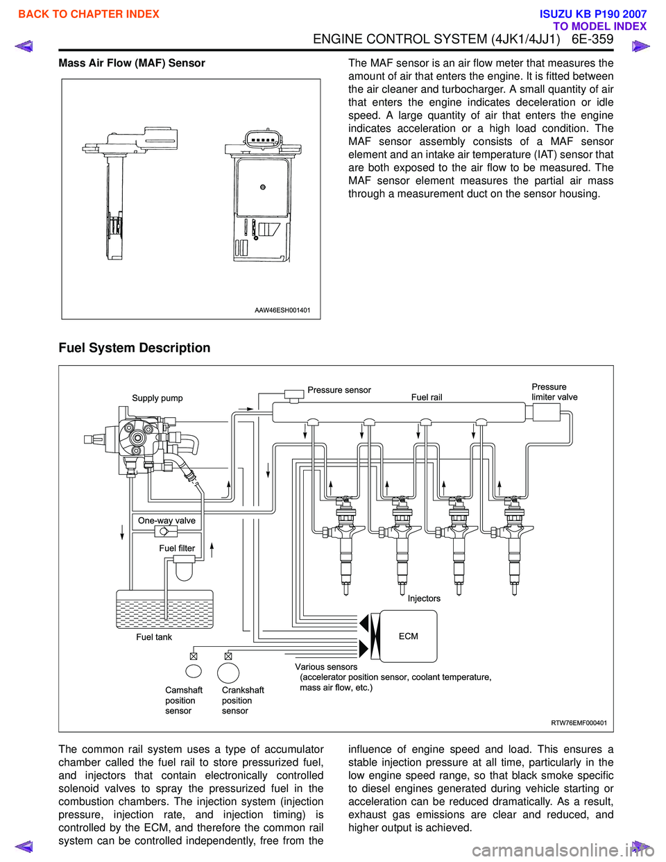
Mass Air Flow (MAF) SensorThe MAF sensor is an air flow meter that measures the
amount of air that enters the engine. It is fitted between
the air cleaner and turbocharger. A small quantity of air
that enters the engine indicates deceleration or idle
speed. A large quantity of air that enters the engine
indicates acceleration or a high load condition. The
MAF sensor assembly consists of a MAF sensor
element and an intake air temperature (IAT) sensor that
are both exposed to the air flow to be measured. The
MAF sensor element measures the partial air mass
through a measurement duct on the sensor housing.
Fuel System Description
The common rail system uses a type of accumulator
chamber called the fuel rail to store pressurized fuel,
and injectors that contain electronically controlled
solenoid valves to spray the pressurized fuel in the
combustion chambers. The injection system (injection
pressure, injection rate, and injection timing) is
controlled by the ECM, and therefore the common rail
system can be controlled independently, free from the influence of engine speed and load. This ensures a
stable injection pressure at all time, particularly in the
low engine speed range, so that black smoke specific
to diesel engines generated during vehicle starting or
acceleration can be reduced dramatically. As a result,
exhaust gas emissions are clear and reduced, and
higher output is achieved.
AAW46ESH001401
RTW76EMF000401
Supply pump
One-way valve
Fuel tank Fuel filter
Camshaft
position
sensor Crankshaft
position
sensor Various sensors
(accelerator position sensor, coolant temperature,
mass air flow, etc.) Injectors
Pressure sensor
Fuel rail Pressure
limiter valve
ECM
BACK TO CHAPTER INDEX
TO MODEL INDEX
ISUZU KB P190 2007
Page 1981 of 6020
6E-364 ENGINE CONTROL SYSTEM (4JK1/4JJ1)
Fuel Injection System Description
Fuel Injection Quantity Control
This control determines the fuel injection quantity by
adding coolant temperature, fuel temperature, intake
air temperature, barometric pressure, mass air flow and
some switch inputs information corrections to the basic
injection quantity is calculated by the ECM based on
the engine operating conditions (engine speed,
accelerator pedal pressing amount and boost pressure
sensor). More fuel rate indicates if the engine load is
increased as the accelerator pedal is stepped on at
constant engine speed.
Combined with high pressure injection of atomized fuel,
this control improves exhaust gas and ensures proper
fuel consumption. Compared with conventional
mechanical governors, an electronic control system
provides higher degree of freedom of fuel injection
quantity control, thereby presenting high accelerator
response (acceleration feeling and pressing feeling).
Starting Injection Quantity Control
At the engine starting (after the key switch is turned to
the START position to start the engine, up to return of
key switch to the ON position), optimum fuel injection
quantity is controlled based on the information on the
engine speed and coolant temperature. At low
temperature, the fuel injection quantity increases.
When the engine started completely, this boosted
quantity mode at the starting is cancelled and normal
running mode is restored.
Idle Speed Control
A control is made so as to achieve stable idling speed
at all time regardless of engine secular changes or
engine condition variations. The ECM sets target idling
speed and controls the fuel injection quantity according
to the engine conditions (actual engine speed, coolant
temperature and engine load) to follow actual engine
speed to the target idling speed so as to ensure stable
idling speed.
Idle Vibration Control
A control is made so as to reduce the engine vibration
caused by torque variations between cylinders due to
variations in fuel injection quantity of each cylinder or
injector performance. The ECM corrects the injection
quantity between cylinders based on the revolution
signals from the crankshaft position (CKP) sensor.
Normal range of correction quantity between cylinders
is within ±5 mm
3.
BACK TO CHAPTER INDEX
TO MODEL INDEX
ISUZU KB P190 2007
Page 1982 of 6020
ENGINE CONTROL SYSTEM (4JK1/4JJ1) 6E-365
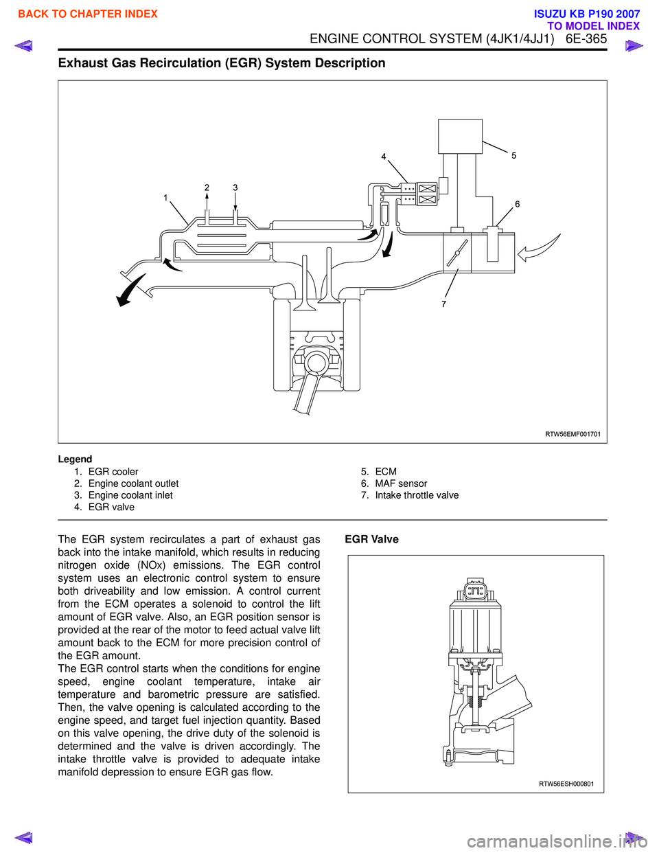
Exhaust Gas Recirculation (EGR) System Description
Legend1. EGR cooler
2. Engine coolant outlet
3. Engine coolant inlet
4. EGR valve 5. ECM
6. MAF sensor
7. Intake throttle valve
The EGR system recirculates a part of exhaust gas
back into the intake manifold, which results in reducing
nitrogen oxide (NOx) emissions. The EGR control
system uses an electronic control system to ensure
both driveability and low emission. A control current
from the ECM operates a solenoid to control the lift
amount of EGR valve. Also, an EGR position sensor is
provided at the rear of the motor to feed actual valve lift
amount back to the ECM for more precision control of
the EGR amount.
The EGR control starts when the conditions for engine
speed, engine coolant temperature, intake air
temperature and barometric pressure are satisfied.
Then, the valve opening is calculated according to the
engine speed, and target fuel injection quantity. Based
on this valve opening, the drive duty of the solenoid is
determined and the valve is driven accordingly. The
intake throttle valve is provided to adequate intake
manifold depression to ensure EGR gas flow. EGR Valve
RTW56EMF001701
1
4
7 5
6
23
RTW56ESH000801
BACK TO CHAPTER INDEX
TO MODEL INDEX
ISUZU KB P190 2007
Page 2004 of 6020
6-4 ENGINE DIAGNOSIS (C24SE)
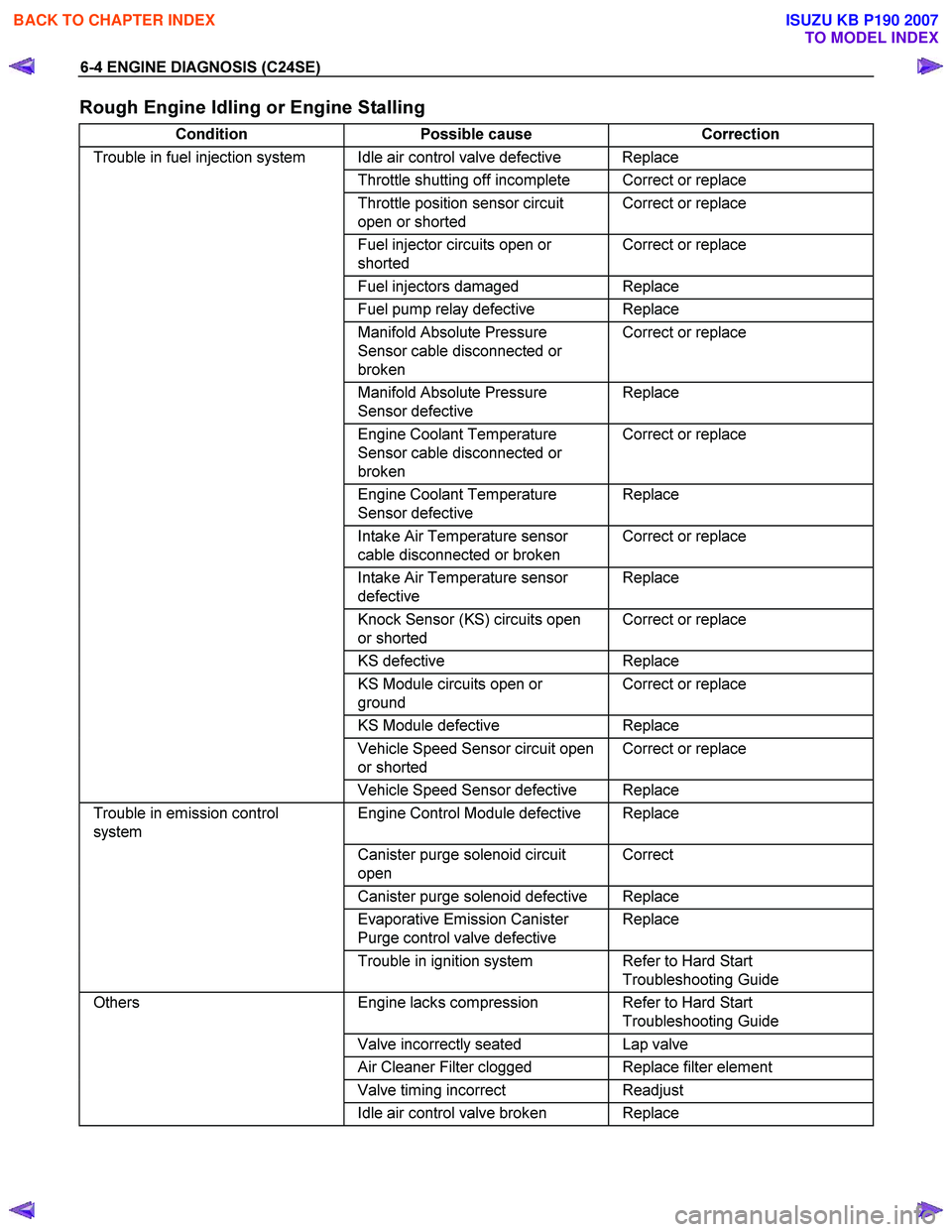
Rough Engine Idling or Engine Stalling
Condition Possible cause Correction
Trouble in fuel injection system Idle air control valve defective Replace
Throttle shutting off incomplete Correct or replace
Throttle position sensor circuit
open or shorted Correct or replace
Fuel injector circuits open or
shorted Correct or replace
Fuel injectors damaged Replace
Fuel pump relay defective Replace
Manifold Absolute Pressure
Sensor cable disconnected or
broken Correct or replace
Manifold Absolute Pressure
Sensor defective Replace
Engine Coolant Temperature
Sensor cable disconnected or
broken Correct or replace
Engine Coolant Temperature
Sensor defective Replace
Intake Air Temperature sensor
cable disconnected or broken Correct or replace
Intake Air Temperature sensor
defective Replace
Knock Sensor (KS) circuits open
or shorted Correct or replace
KS
defective Replace
KS Module circuits open or
ground Correct or replace
KS Module defective Replace
Vehicle Speed Sensor circuit open
or shorted Correct or replace
Vehicle Speed Sensor defective Replace
Trouble in emission control
system Engine Control Module defective Replace
Canister purge solenoid circuit
open Correct
Canister purge solenoid defective Replace
Evaporative Emission Canister
Purge control valve defective Replace
Trouble in ignition system Refer to Hard Start
Troubleshooting Guide
Others Engine lacks compression Refer to Hard Start
Troubleshooting Guide
Valve incorrectly seated Lap valve
Air Cleaner Filter clogged Replace filter element
Valve timing incorrect Readjust
Idle air control valve broken Replace
BACK TO CHAPTER INDEX
TO MODEL INDEX
ISUZU KB P190 2007
Page 2005 of 6020
ENGINE DIAGNOSIS (C24SE) 6-5
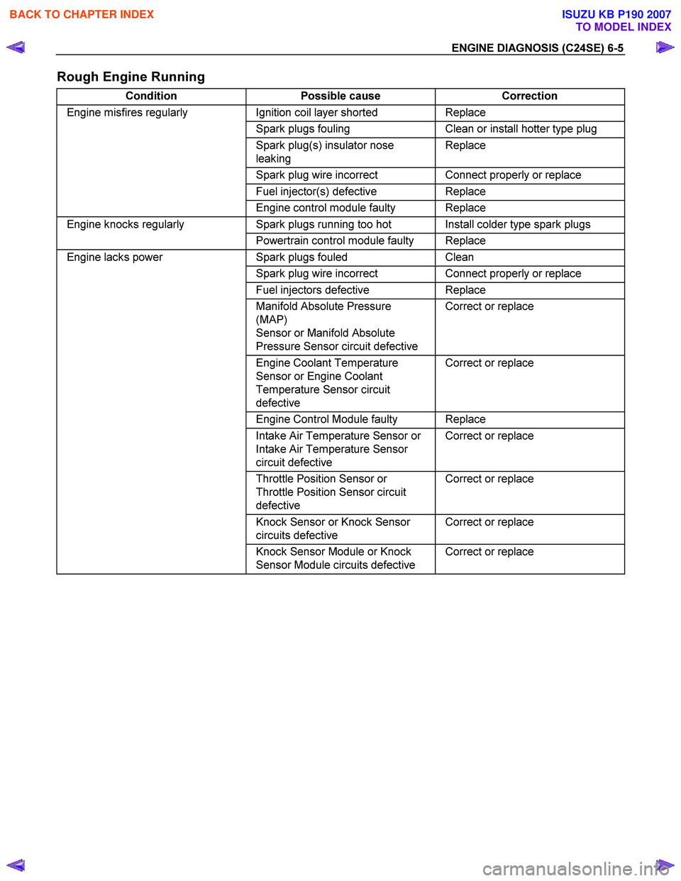
Rough Engine Running
Condition Possible cause Correction
Engine misfires regularly Ignition coil layer shorted Replace
Spark plugs fouling Clean or install hotter type plug
Spark plug(s) insulator nose
leaking Replace
Spark plug wire incorrect Connect properly or replace
Fuel injector(s) defective Replace
Engine control module faulty Replace
Engine knocks regularly Spark plugs running too hot Install colder type spark plugs
Powertrain control module faulty Replace
Engine lacks power Spark plugs fouled Clean
Spark plug wire incorrect Connect properly or replace
Fuel injectors defective Replace
Manifold Absolute Pressure
(MAP)
Sensor or Manifold Absolute
Pressure Sensor circuit defective Correct or replace
Engine Coolant Temperature
Sensor or Engine Coolant
Temperature Sensor circuit
defective Correct or replace
Engine Control Module faulty Replace
Intake Air Temperature Sensor or
Intake Air Temperature Sensor
circuit defective Correct or replace
Throttle Position Sensor or
Throttle Position Sensor circuit
defective Correct or replace
Knock Sensor or Knock Sensor
circuits defective Correct or replace
Knock Sensor Module or Knock
Sensor Module circuits defective Correct or replace
BACK TO CHAPTER INDEX
TO MODEL INDEX
ISUZU KB P190 2007
Page 2006 of 6020
6-6 ENGINE DIAGNOSIS (C24SE)
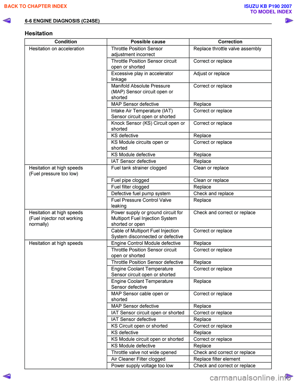
Hesitation
Condition Possible cause Correction
Hesitation on acceleration Throttle Position Sensor
adjustment incorrect Replace throttle valve assembly
Throttle Position Sensor circuit
open or shorted Correct or replace
Excessive play in accelerator
linkage Adjust or replace
Manifold Absolute Pressure
(MAP) Sensor circuit open or
shorted Correct or replace
MAP Sensor defective Replace
Intake Air Temperature (IAT)
Sensor circuit open or shorted Correct or replace
Knock Sensor (KS) Circuit open or
shorted Correct or replace
KS
defective Replace
KS Module circuits open or
shorted Correct or replace
KS Module defective Replace
IAT Sensor defective Replace
Hesitation at high speeds
(Fuel pressure too low) Fuel tank strainer clogged Clean or replace
Fuel pipe clogged Clean or replace
Fuel filter clogged Replace
Defective fuel pump system Check and replace
Fuel Pressure Control Valve
leaking Replace
Hesitation at high speeds
(Fuel injector not working
normally) Power supply or ground circuit for
Multiport Fuel Injection System
shorted or open Check and correct or replace
Cable of Multiport Fuel Injection
System disconnected or defective Correct or replace
Hesitation at high speeds
Engine Control Module defective Replace
Throttle Position Sensor circuit
open or shorted Correct or replace
Throttle Position Sensor defective Replace
Engine Coolant Temperature
Sensor circuit open or shorted Correct or replace
Engine Coolant Temperature
Sensor defective Replace
MAP Sensor cable open or
shorted Correct or replace
MAP Sensor defective Replace
IAT Sensor circuit open or shorted Correct or replace
IAT Sensor defective Replace
KS Circuit open or shorted Correct or replace
KS defective Replace
KS Module circuit open or shorted Correct or replace
KS Module defective Replace
Throttle valve not wide opened Check and correct or replace
Air Cleaner Filter clogged Replace filter element
Power supply voltage too low Check and correct or replace
BACK TO CHAPTER INDEX
TO MODEL INDEX
ISUZU KB P190 2007