Page 2007 of 6020
ENGINE DIAGNOSIS (C24SE) 6-7
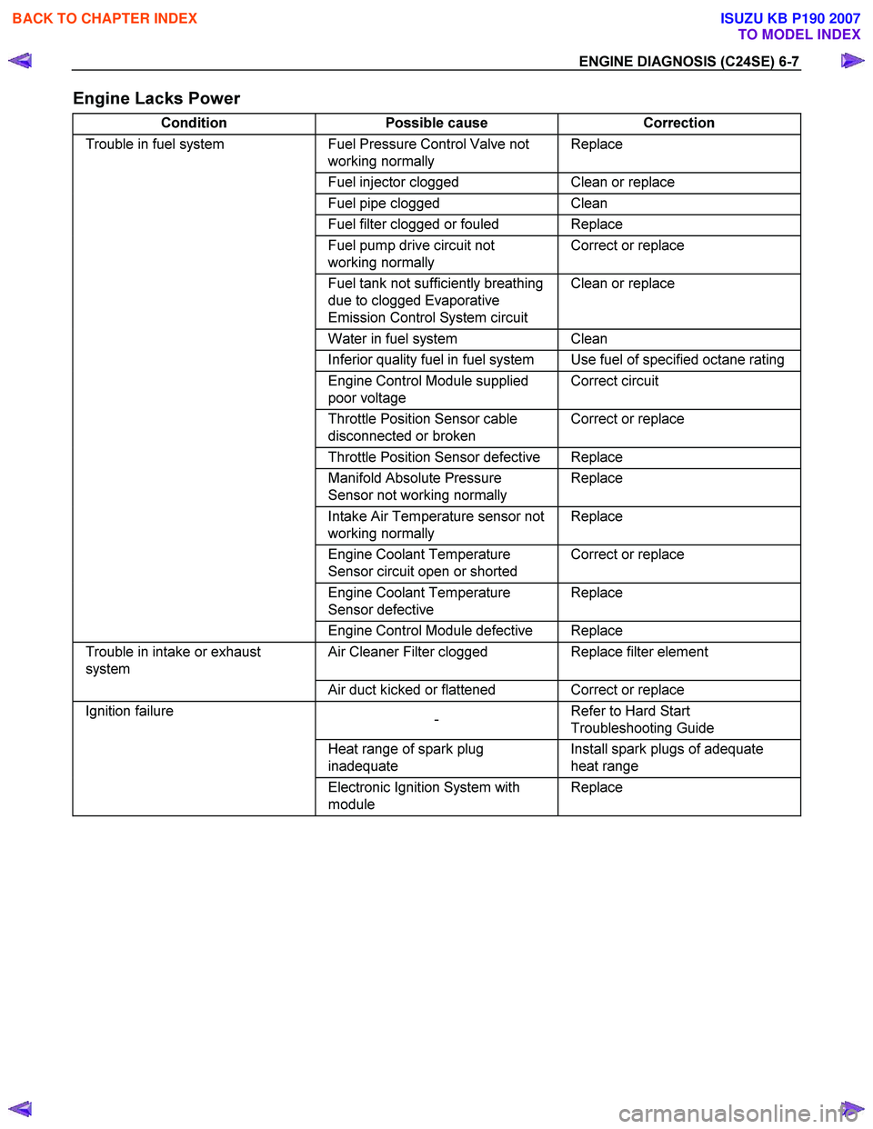
Engine Lacks Power
Condition Possible cause Correction
Trouble in fuel system Fuel Pressure Control Valve not
working normally Replace
Fuel injector clogged Clean or replace
Fuel pipe clogged Clean
Fuel filter clogged or fouled Replace
Fuel pump drive circuit not
working normally Correct or replace
Fuel tank not sufficiently breathing
due to clogged Evaporative
Emission Control System circuit Clean or replace
Water in fuel system Clean
Inferior quality fuel in fuel system Use fuel of specified octane rating
Engine Control Module supplied
poor voltage Correct circuit
Throttle Position Sensor cable
disconnected or broken Correct or replace
Throttle Position Sensor defective Replace
Manifold Absolute Pressure
Sensor not working normally Replace
Intake Air Temperature sensor not
working normally Replace
Engine Coolant Temperature
Sensor circuit open or shorted Correct or replace
Engine Coolant Temperature
Sensor defective Replace
Engine Control Module defective Replace
Trouble in intake or exhaust
system Air Cleaner Filter clogged Replace filter element
Air duct kicked or flattened Correct or replace
Ignition failure
- Refer to Hard Start
Troubleshooting Guide
Heat range of spark plug
inadequate Install spark plugs of adequate
heat range
Electronic Ignition System with
module Replace
BACK TO CHAPTER INDEX
TO MODEL INDEX
ISUZU KB P190 2007
Page 2011 of 6020
ENGINE DIAGNOSIS (C24SE) 6-11
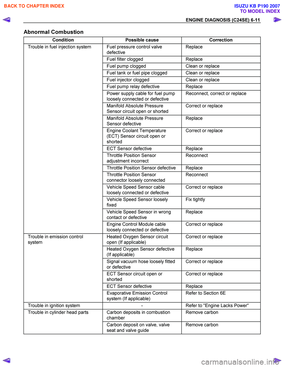
Abnormal Combustion
Condition Possible cause Correction
Trouble in fuel injection system Fuel pressure control valve
defective Replace
Fuel filter clogged Replace
Fuel pump clogged Clean or replace
Fuel tank or fuel pipe clogged Clean or replace
Fuel injector clogged Clean or replace
Fuel pump relay defective Replace
Power supply cable for fuel pump
loosely connected or defective Reconnect, correct or replace
Manifold Absolute Pressure
Sensor circuit open or shorted Correct or replace
Manifold Absolute Pressure
Sensor defective Replace
Engine Coolant Temperature
(ECT) Sensor circuit open or
shorted Correct or replace
ECT Sensor defective Replace
Throttle Position Sensor
adjustment incorrect Reconnect
Throttle Position Sensor defective Replace
Throttle Position Sensor
connector loosely connected Reconnect
Vehicle Speed Sensor cable
loosely connected or defective Correct or replace
Vehicle Speed Sensor loosely
fixed Fix tightly
Vehicle Speed Sensor in wrong
contact or defective Replace
Engine Control Module cable
loosely connected or defective Correct or replace
Trouble in emission control
system Heated Oxygen Sensor circuit
open (If applicable) Correct or replace
Heated Oxygen Sensor defective
(If applicable) Replace
Signal vacuum hose loosely fitted
or defective Correct or replace
ECT Sensor circuit open or
shorted Correct or replace
ECT Sensor defective Replace
Evaporative Emission Control
system (If applicable) Refer to Section 6E
Trouble in ignition system
- Refer to "Engine Lacks Power"
Trouble in cylinder head parts Carbon deposits in combustion
chamber Remove carbon
Carbon deposit on valve, valve
seat and valve guide Remove carbon
BACK TO CHAPTER INDEX
TO MODEL INDEX
ISUZU KB P190 2007
Page 2014 of 6020
6-14 ENGINE DIAGNOSIS (C24SE)
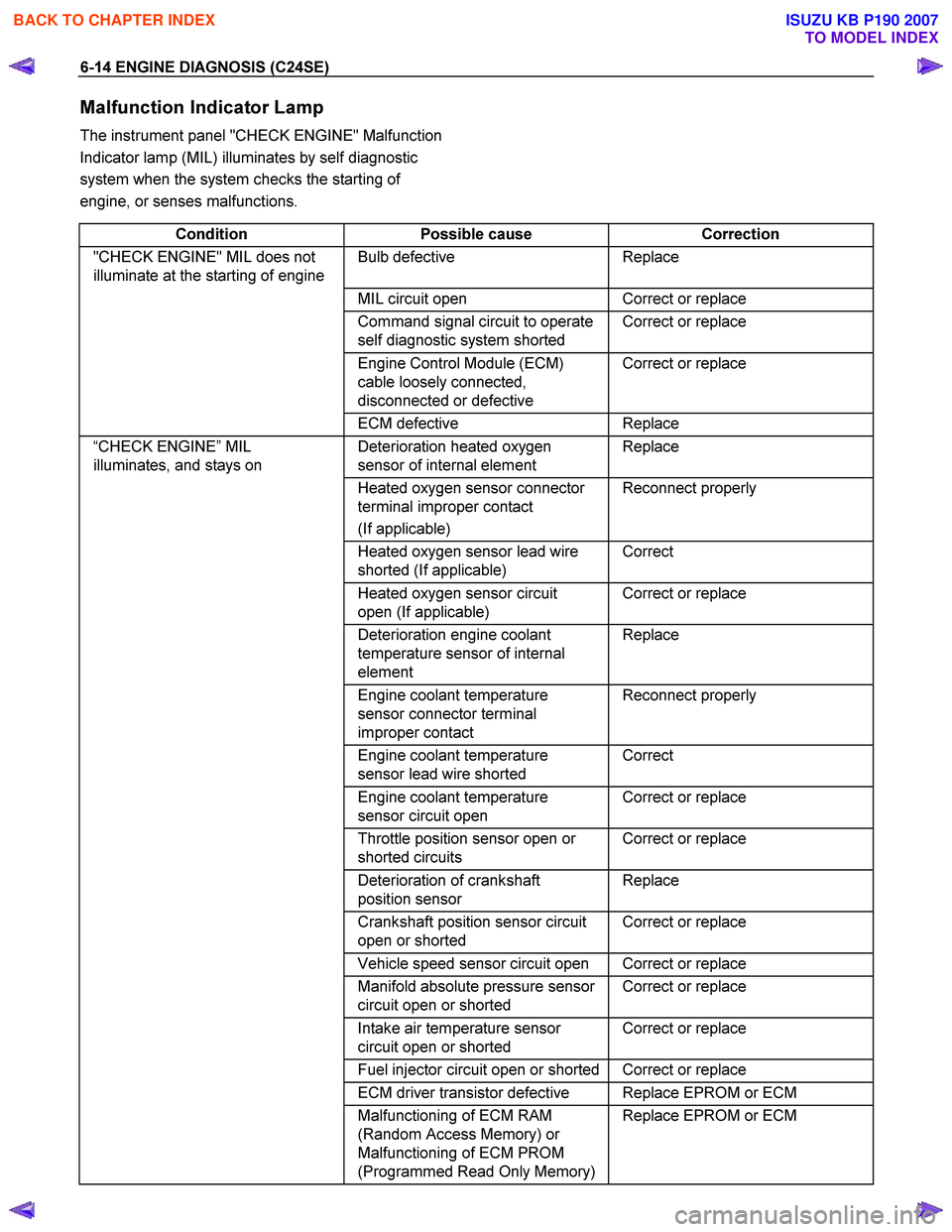
Malfunction Indicator Lamp
The instrument panel "CHECK ENGINE" Malfunction
Indicator lamp (MIL) illuminates by self diagnostic
system when the system checks the starting of
engine, or senses malfunctions.
Condition Possible cause Correction
"CHECK ENGINE" MIL does not
illuminate at the starting of engine Bulb defective Replace
MIL circuit open Correct or replace
Command signal circuit to operate
self diagnostic system shorted Correct or replace
Engine Control Module (ECM)
cable loosely connected,
disconnected or defective Correct or replace
ECM
defective Replace
“CHECK ENGINE” MIL
illuminates, and stays on Deterioration heated oxygen
sensor of internal element Replace
Heated oxygen sensor connector
terminal improper contact
(If applicable) Reconnect properly
Heated oxygen sensor lead wire
shorted (If applicable) Correct
Heated oxygen sensor circuit
open (If applicable) Correct or replace
Deterioration engine coolant
temperature sensor of internal
element Replace
Engine coolant temperature
sensor connector terminal
improper contact Reconnect properly
Engine coolant temperature
sensor lead wire shorted Correct
Engine coolant temperature
sensor circuit open Correct or replace
Throttle position sensor open or
shorted circuits Correct or replace
Deterioration of crankshaft
position sensor Replace
Crankshaft position sensor circuit
open or shorted Correct or replace
Vehicle speed sensor circuit open Correct or replace
Manifold absolute pressure sensor
circuit open or shorted Correct or replace
Intake air temperature sensor
circuit open or shorted Correct or replace
Fuel injector circuit open or shorted Correct or replace
ECM driver transistor defective Replace EPROM or ECM
Malfunctioning of ECM RAM
(Random Access Memory) or
Malfunctioning of ECM PROM
(Programmed Read Only Memory) Replace EPROM or ECM
BACK TO CHAPTER INDEX
TO MODEL INDEX
ISUZU KB P190 2007
Page 2041 of 6020
ENGINE MECHANICAL (C24SE) 6A-27
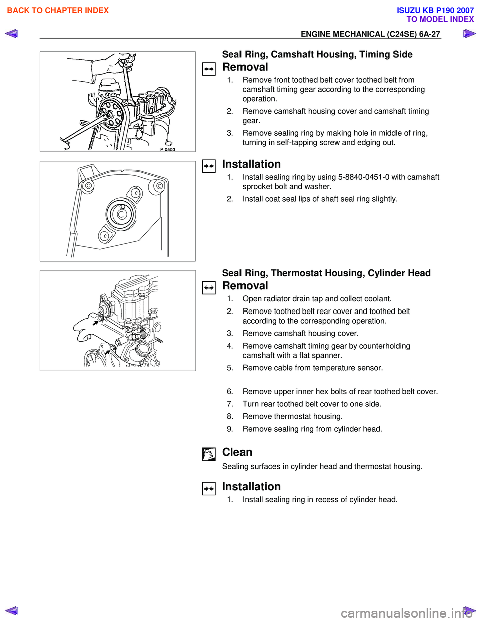
Seal Ring, Camshaft Housing, Timing Side
Removal
1. Remove front toothed belt cover toothed belt from camshaft timing gear according to the corresponding
operation.
2. Remove camshaft housing cover and camshaft timing gear.
3. Remove sealing ring by making hole in middle of ring, turning in self-tapping screw and edging out.
Installation
1. Install sealing ring by using 5-8840-0451-0 with camshaft sprocket bolt and washer.
2. Install coat seal lips of shaft seal ring slightly.
Seal Ring, Thermostat Housing, Cylinder Head
Removal
1. Open radiator drain tap and collect coolant.
2. Remove toothed belt rear cover and toothed belt according to the corresponding operation.
3. Remove camshaft housing cover.
4. Remove camshaft timing gear by counterholding camshaft with a flat spanner.
5. Remove cable from temperature sensor.
6. Remove upper inner hex bolts of rear toothed belt cover.
7. Turn rear toothed belt cover to one side.
8. Remove thermostat housing.
9. Remove sealing ring from cylinder head.
Clean
Sealing surfaces in cylinder head and thermostat housing.
Installation
1. Install sealing ring in recess of cylinder head.
BACK TO CHAPTER INDEX
TO MODEL INDEX
ISUZU KB P190 2007
Page 2049 of 6020
ENGINE MECHANICAL (C24SE) 6A-35
Camshaft Housing, Removal and
Installation
Cylinder Head
Important!
Remove cylinder head only from cold engine (room
temperature).
Removal
1. Remove ground cable from battery.
2. Open radiator drain tap and collect coolant.
3. Remove air intake hose.
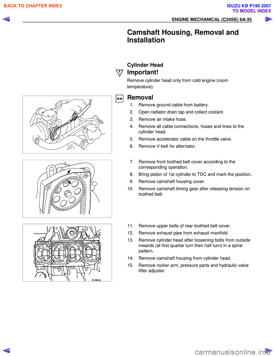
4. Remove all cable connections, hoses and lines to the cylinder head.
5. Remove accelerator cable on the throttle valve.
6. Remove V-belt for alternator.
7. Remove front toothed belt cover according to the
corresponding operation.
8. Bring piston of 1st cylinder to TDC and mark the position.
9. Remove camshaft housing cover.
10. Remove camshaft timing gear after releasing tension on toothed belt.
11. Remove upper bolts of rear toothed belt cover.
12. Remove exhaust pipe from exhaust manifold.
13. Remove cylinder head after loosening bolts from outside inwards (at first quarter turn then half turn) in a spiral
pattern.
14. Remove camshaft housing from cylinder head.
15. Remove rocker arm, pressure parts and hydraulic valve lifter adjuster.
BACK TO CHAPTER INDEX
TO MODEL INDEX
ISUZU KB P190 2007
Page 2077 of 6020
ENGINE MECHANICAL (C24SE) 6A-63
OPERATIONS ON COOLING SYSTEM
Caution!
Before working with the cooling system, be sure to confirm that
the temperature of the engine is cooled down.
Failure to observe this may cause burn.
Cooling System, Check for Leaks
Installation
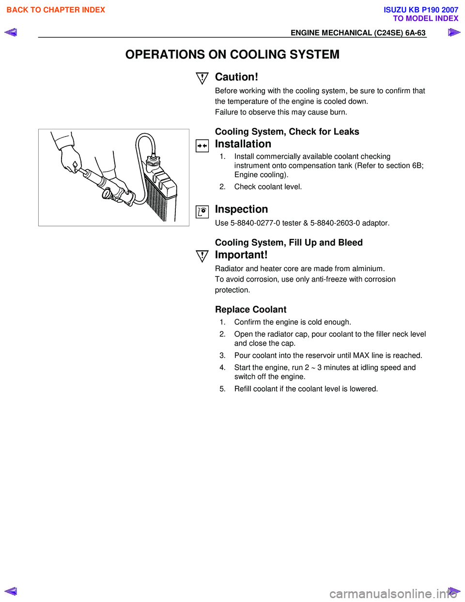
1. Install commercially available coolant checking instrument onto compensation tank (Refer to section 6B;
Engine cooling).
2. Check coolant level.
Inspection
Use 5-8840-0277-0 tester & 5-8840-2603-0 adaptor.
Cooling System, Fill Up and Bleed
Important!
Radiator and heater core are made from alminium.
To avoid corrosion, use only anti-freeze with corrosion
protection.
Replace Coolant
1. Confirm the engine is cold enough.
2. Open the radiator cap, pour coolant to the filler neck level and close the cap.
3. Pour coolant into the reservoir until MAX line is reached.
4. Start the engine, run 2 ∼ 3 minutes at idling speed and
switch off the engine.
5. Refill coolant if the coolant level is lowered.
BACK TO CHAPTER INDEX
TO MODEL INDEX
ISUZU KB P190 2007
Page 2078 of 6020
6A-64 ENGINE MECHANICAL (C24SE)
Important!
Do not loosen or open the radiator cap when coolant is hot.
Doing so may cause hot water or steam to splash out, resulting
in burn. W hen opening the radiator cap, be sure to confirm the
coolant is cold. Cover a thick cloth over the cap and loosen it
slowly to reduce pressure, then open the cap.
6. Close the radiator cap firmly and run the engine at approx. 2000 rpm. In addition, set the heater temperature
adjuster to the max position to circulate coolant in the
heater conduit system.
7. Confirm that the temperature gauge reads half or more of full scale and that the thermostat is activated.
Then continue idling 5 minutes more and switch off the
engine, and allow it to cool.
8. After the engine cools down, check the coolant level and refill it if necessary. W hen the level is lowered extremely,
check the coolant conduit system and reservoir hose for
leak.
9. Pour coolant into the reservoir to MAX level.
Refill Coolant
Important!
After closing the cooling system, let engine run warm until
thermostat opens (coolant approx. 92 °C/197.6F)
Inspection
Coolant level
Allow engine to cool. If necessary, refill coolant.
Check that cooling system self-bleeds during engine warming-
up phase.
Ignition Timing, Check
No Adjustment
BACK TO CHAPTER INDEX
TO MODEL INDEX
ISUZU KB P190 2007
Page 2085 of 6020
ENGINE MECHANICAL (C24SE) 6A-71
Installation
(2.4L)
1. Install the ECM to the ECM bracket on engine.
2. Tighten the four screws to the bracket.
3. Connect the connector.
ECT
Removal
1. Remove wiring harness plug and coolant temperature sensor.
Tighten (Torque)
Temperature sensor to intake pipe - 10 N ⋅m (1.0 kgf ⋅m)
W iring harness plug to temperature sensor
Inspection
Coolant level
Idle Air Control (IAC) Valve
Removal
1. Remove wiring harness plug, hose clamps and idle speed adjuster.
Installation
1. Install idle speed adjuster, hose clamps and wiring harness plug.
Ignition Coil
Removal
1. Remove 2 bolts, plug and ignition coil.
Installation
1. Install ignition coil, plug and bolts.
BACK TO CHAPTER INDEX
TO MODEL INDEX
ISUZU KB P190 2007