2007 ISUZU KB P190 coolant temperature
[x] Cancel search: coolant temperaturePage 2091 of 6020
ENGINE MECHANICAL (C24SE) 6A-77
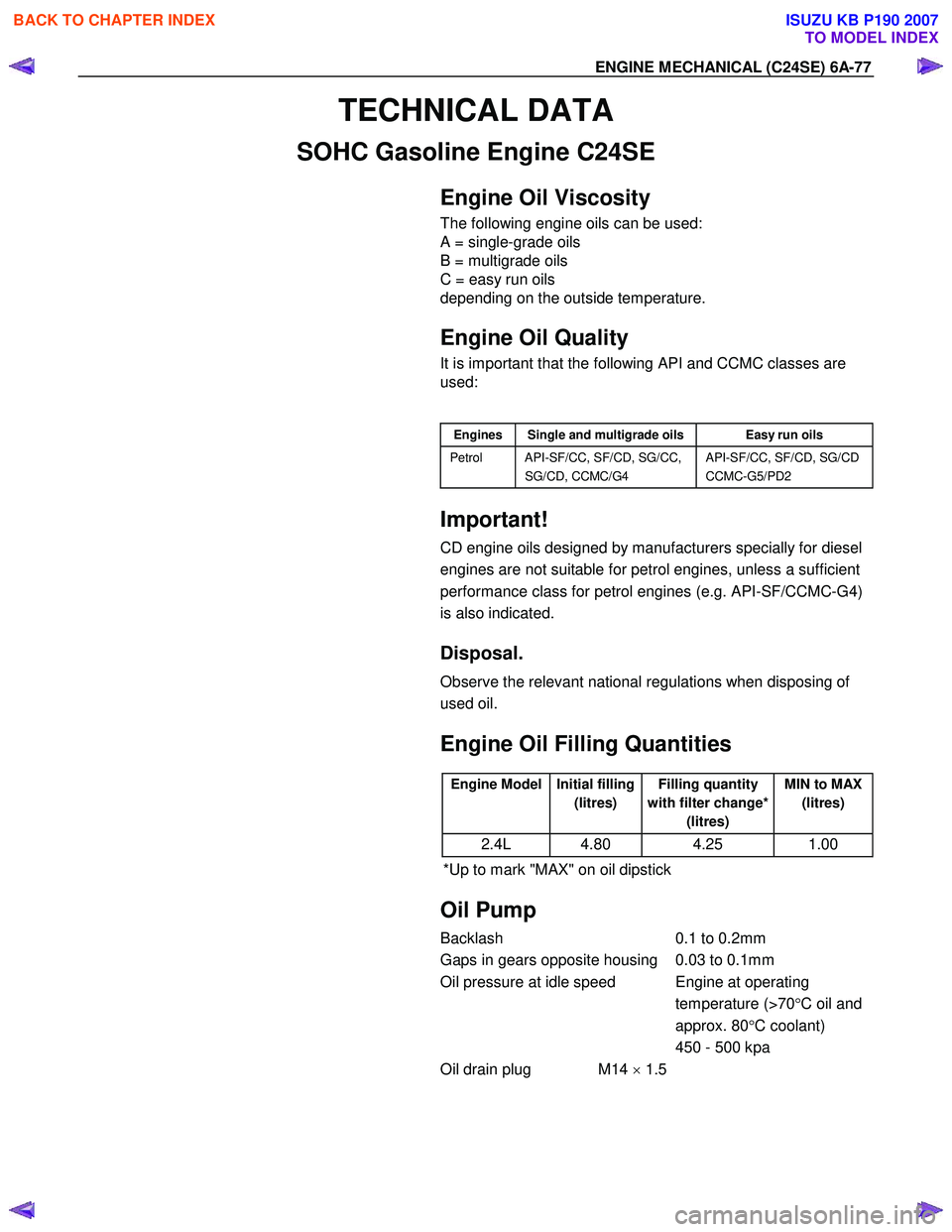
TECHNICAL DATA
SOHC Gasoline Engine C24SE
Engine Oil Viscosity
The following engine oils can be used:
A = single-grade oils
B = multigrade oils
C = easy run oils
depending on the outside temperature.
Engine Oil Quality
It is important that the following API and CCMC classes are
used:
Engines Single and multigrade oils Easy run oils
Petrol API-SF/CC, SF/CD, SG/CC,
SG/CD, CCMC/G4 API-SF/CC, SF/CD, SG/CD
CCMC-G5/PD2
Important!
CD engine oils designed by manufacturers specially for diesel
engines are not suitable for petrol engines, unless a sufficient
performance class for petrol engines (e.g. API-SF/CCMC-G4)
is also indicated.
Disposal.
Observe the relevant national regulations when disposing of
used oil.
Engine Oil Filling Quantities
Engine Model Initial filling
(litres) Filling quantity
with filter change* (litres) MIN to MAX
(litres)
2.4L 4.80 4.25 1.00
*Up to mark "MAX" on oil dipstick
Oil Pump
Backlash 0.1 to 0.2mm
Gaps in gears opposite housing 0.03 to 0.1mm
Oil pressure at idle speed Engine at operating temperature (>70°C oil and
approx. 80 °C coolant)
450 - 500 kpa
Oil drain plug M14 × 1.5
BACK TO CHAPTER INDEX
TO MODEL INDEX
ISUZU KB P190 2007
Page 2108 of 6020
6B-4 ENGINE COOLING
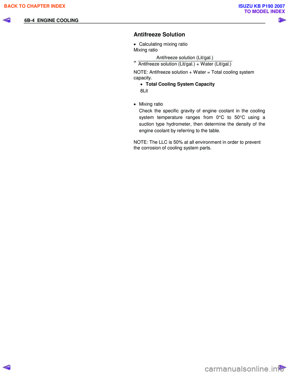
Antifreeze Solution
• Calculating mixing ratio
Mixing ratio
= Antifreeze solution (Lit/gal.)
Antifreeze solution (Lit/gal.) + W ater (Lit/gal.)
NOTE: Antifreeze solution + W ater = Total cooling system
capacity.
• Total Cooling System Capacity
8Lit
• Mixing ratio
Check the specific gravity of engine coolant in the cooling system temperature ranges from 0 °C to 50 °C using a
suction type hydrometer, then determine the density of the
engine coolant by referring to the table.
NOTE: The LLC is 50% at all environment in order to prevent
the corrosion of cooling system parts.
BACK TO CHAPTER INDEX
TO MODEL INDEX
ISUZU KB P190 2007
Page 2109 of 6020
ENGINE COOLING 6B-5
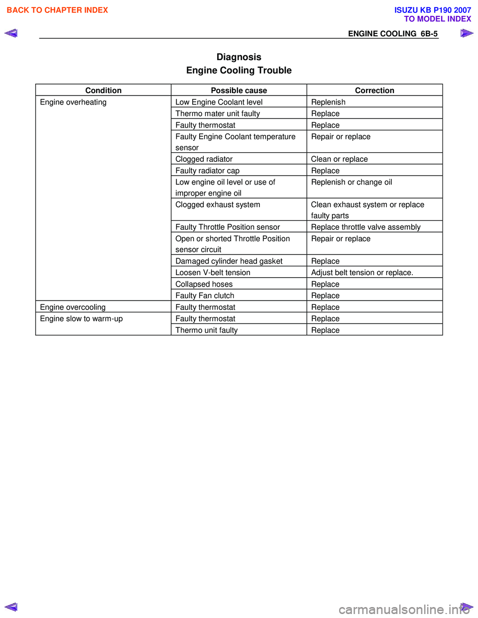
Diagnosis
Engine Cooling Trouble
Condition Possible cause Correction
Engine overheating Low Engine Coolant level Replenish
Thermo mater unit faulty Replace
Faulty thermostat Replace
Faulty Engine Coolant temperature
sensor Repair or replace
Clogged radiator Clean or replace
Faulty radiator cap Replace
Low engine oil level or use of
improper engine oil Replenish or change oil
Clogged exhaust system Clean exhaust system or replace
faulty parts
Faulty Throttle Position sensor Replace throttle valve assembly
Open or shorted Throttle Position
sensor circuit Repair or replace
Damaged cylinder head gasket Replace
Loosen V-belt tension Adjust belt tension or replace.
Collapsed hoses Replace
Faulty Fan clutch Replace
Engine overcooling Faulty thermostat Replace
Engine slow to warm-up Faulty thermostat Replace
Thermo unit faulty Replace
BACK TO CHAPTER INDEX
TO MODEL INDEX
ISUZU KB P190 2007
Page 2113 of 6020
ENGINE COOLING 6B-9
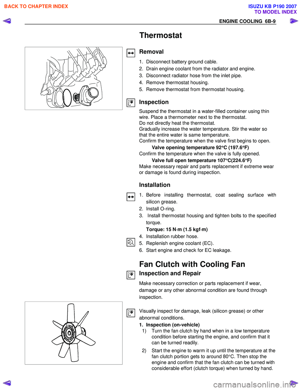
Thermostat
Removal
1. Disconnect battery ground cable.
2. Drain engine coolant from the radiator and engine.
3. Disconnect radiator hose from the inlet pipe.
4. Remove thermostat housing.
5. Remove thermostat from thermostat housing.
Inspection
Suspend the thermostat in a water-filled container using thin
wire. Place a thermometer next to the thermostat.
Do not directly heat the thermostat.
Gradually increase the water temperature. Stir the water so
that the entire water is same temperature.
Confirm the temperature when the valve first begins to open.
Valve opening temperature 92 °
°°
°
C (197.6 °
°°
°
F)
Confirm the temperature when the valve is fully opened.
Valve full open temperature 107 °
°°
°
C(224.6 °
°°
°
F)
Make necessary repair and parts replacement if extreme wear
or damage is found during inspection.
Installation
1. Before installing thermostat, coat sealing surface with
silicon grease.
2. Install O-ring.
3. Install thermostat housing and tighten bolts to the specified torque.
Torque: 15 N ⋅
⋅⋅
⋅
m (1.5 kgf ⋅
⋅⋅
⋅
m)
4. Installation rubber hose.
5. Replenish engine coolant (EC).
6. Start engine and check for EC leakage.
Fan Clutch with Cooling Fan
Inspection and Repair
Make necessary correction or parts replacement if wear,
damage or any other abnormal condition are found through
inspection.
Visually inspect for damage, leak (silicon grease) or other
abnormal conditions.
1. Inspection (on-vehicle)
1) Turn the fan clutch by hand when in a low temperature condition before starting the engine, and confirm that it
can be turned readily.
2) Start the engine to warm it up until the temperature at the fan clutch portion gets to around 80 °C. Then stop the
engine and confirm that the fan clutch can be turned with
considerable effort (clutch torque) when turned by hand.
BACK TO CHAPTER INDEX
TO MODEL INDEX
ISUZU KB P190 2007
Page 2117 of 6020
ENGINE COOLING 6B-13
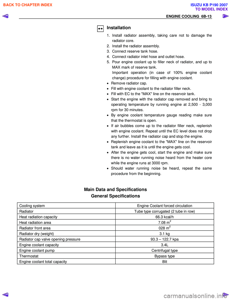
Installation
1. Install radiator assembly, taking care not to damage theradiator core.
2. Install the radiator assembly.
3. Connect reserve tank hose.
4. Connect radiator inlet hose and outlet hose.
5. Pour engine coolant up to filler neck of radiator, and up to MAX mark of reserve tank.
Important operation (in case of 100% engine coolant change) procedure for filling with engine coolant.
• Remove radiator cap.
• Fill with engine coolant to the radiator filler neck.
• Fill with EC to the "MAX" line on the reservoir tank.
• Start the engine with the radiator cap removed and bring to
operating temperature by running engine at 2,500 - 3,000
rpm for 30 minutes.
• By engine coolant temperature gauge reading make sure
that the thermostat is open.
• If air bubbles come up to the radiator filler neck, replenish
with engine coolant. Repeat until the EC level does not drop
any further. Install the radiator cap and stop the engine.
• Replenish engine coolant to the "MAX" line on the reservoi
r
tank and leave as it is until the engine gets cool.
•
After the engine gets cool, start the engine and make sure
there is no water running noise heard from the heater core
while the engine runs at 3000 rpm.
• Should water running noise be heard, repeat the same
procedure from the beginning.
Main Data and Specifications
General Specifications
Cooling system Engine Coolant forced circulation
Radiator Tube type corrugated (2 tube in row)
Heat radiation capacity 66.3 kcal/h
Heat radiation area 7.08 m2
Radiator front area 028 m2
Radiator dry (weight) 3.1 kg
Radiator cap valve opening pressure 93.3 – 122.7 kpa
Engine coolant capacity 3.4L
Engine coolant pump Centrifugal type
Thermostat Bypass type
Engine coolant total capacity 8lit
BACK TO CHAPTER INDEX
TO MODEL INDEX
ISUZU KB P190 2007
Page 2171 of 6020
SECTION 6E
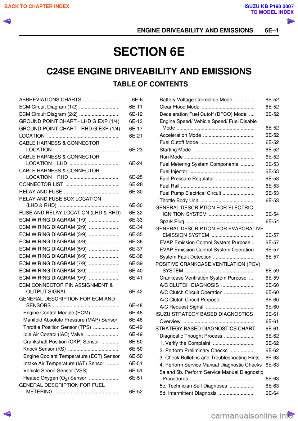
TABLE OF CONTENTS
C24SE ENGINE DRIVEABILITY AND EMISSIONS
ABBREVIATIONS CHARTS ......................... 6E-6
ECM Circuit Diagram (1/2) ............................ 6E-11
ECM Circuit Diagram (2/2) ............................ 6E-12
GROUND POINT CHART - LHD G.EXP (1/4) 6E-13
GROUND POINT CHART - RHD G.EXP (1/4) 6E-17
LOCATION ................................................... 6E-21
CABLE HARNESS & CONNECTOR LOCATION .............................................. 6E-23
CABLE HARNESS & CONNECTOR LOCATION - LHD ................................... 6E-24
CABLE HARNESS & CONNECTOR LOCATION - RHD ................................... 6E-25
CONNECTOR LIST ...................................... 6E-28
RELAY AND FUSE ....................................... 6E-30
RELAY AND FUSE BOX LOCATION (LHD & RHD) ........................................... 6E-30
FUSE AND RELAY LOCATION (LHD & RHD) 6E-32
ECM WIRING DIAGRAM (1/9) ..................... 6E-33
ECM WIRING DIAGRAM (2/9) ..................... 6E-34
ECM WIRING DIAGRAM (3/9) ..................... 6E-35
ECM WIRING DIAGRAM (4/9) ..................... 6E-36
ECM WIRING DIAGRAM (5/9) ..................... 6E-37
ECM WIRING DIAGRAM (6/9) ..................... 6E-38
ECM WIRING DIAGRAM (7/9) ..................... 6E-39
ECM WIRING DIAGRAM (8/9) ..................... 6E-40
ECM WIRING DIAGRAM (9/9) ..................... 6E-41
ECM CONNECTOR PIN ASSIGNMENT & OUTPUT SIGNAL .................................... 6E-42
GENERAL DESCRIPTION FOR ECM AND SENSORS ............................................... 6E-48
Engine Control Module (ECM) ................... 6E-48
Manifold Absolute Pressure (MAP) Sensor 6E-48
Throttle Position Sensor (TPS) .................. 6E-49
Idle Air Control (IAC) Valve ....................... 6E-49
Crankshaft Position (CKP) Sensor ............ 6E-50
Knock Sensor (KS) .................................... 6E-50
Engine Coolant Temperature (ECT) Sensor 6E-50
Intake Air Temperature (IAT) Sensor ........ 6E-51
Vehicle Speed Sensor (VSS) .................... 6E-51
Heated Oxygen (O
2) Sensor ..................... 6E-51
GENERAL DESCRIPTION FOR FUEL METERING .............................................. 6E-52 Battery Voltage Correction Mode ............... 6E-52
Clear Flood Mode ...................................... 6E-52
Deceleration Fuel Cutoff (DFCO) Mode .... 6E-52
Engine Speed/ Vehicle Speed/ Fuel Disable Mode ........................................................ 6E-52
Acceleration Mode ..................................... 6E-52
Fuel Cutoff Mode ....................................... 6E-52
Starting Mode ............................................ 6E-52
Run Mode .................................................. 6E-52
Fuel Metering System Components .......... 6E-53
Fuel Injector ............................................... 6E-53
Fuel Pressure Regulator ............................ 6E-53
Fuel Rail ..................................................... 6E-53
Fuel Pump Electrical Circuit ....................... 6E-53
Thottle Body Unit ....................................... 6E-53
GENERAL DESCRIPTION FOR ELECTRIC IGNITION SYSTEM ................................. 6E-54
Spark Plug ................................................. 6E-54
GENERAL DESCRIPTION FOR EVAPORATIVE EMISSION SYSTEM ............................... 6E-57
EVAP Emission Control System Purpose .. 6E-57
EVAP Emission Control System Operation 6E-57
System Fault Detection .............................. 6E-57
POSITIVE CRANKCASE VENTILATION (PCV) SYSTEM .................................................. 6E-59
Crankcase Ventilation System Purpose .... 6E-59
A/C CLUTCH DIAGNOSIS ........................ 6E-60
A/C Clutch Circuit Operation ...................... 6E-60
A/C Clutch Circuit Purpose ........................ 6E-60
A/C Request Signal ................................... 6E-60
ISUZU STRATEGY BASED DIAGNOSTICS 6E-61
Overview .................................................... 6E-61
STRATEGY BASED DIAGNOSTICS CHART 6E-61 Diagnostic Thought Process ...................... 6E-62
1. Verify the Complaint .............................. 6E-62
2. Perform Preliminary Checks .................. 6E-62
3. Check Bulletins and Troubleshooting Hints 6E-63
4. Perform Service Manual Diagnostic Checks 6E-63
5a and 5b. Perform Service Manual Diagnostic Procedures .............................................. 6E-63
5c. Technician Self Diagnoses .................. 6E-63
5d. Intermittent Diagnosis .......................... 6E-64
6 E –1
E N GINE DRIV EABILITY AND E M IS SIONS
BACK TO CHAPTER INDEX
TO MODEL INDEX
ISUZU KB P190 2007
Page 2172 of 6020
6E–2 ENGINE DRIVEABILITY AND EMISSIONS
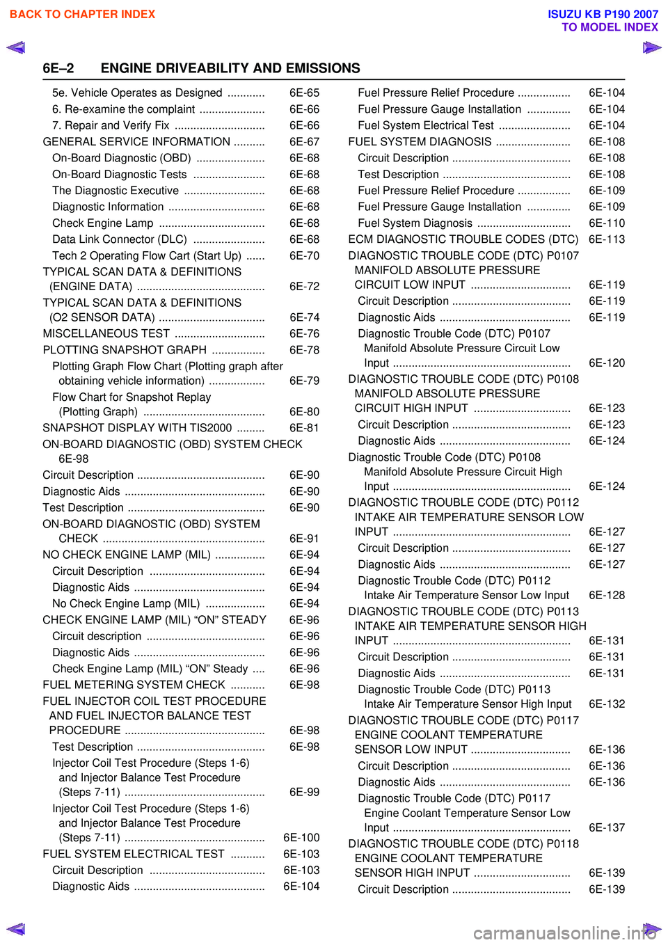
5e. Vehicle Operates as Designed ............ 6E-65
6. Re-examine the complaint ..................... 6E-66
7. Repair and Verify Fix ............................. 6E-66
GENERAL SERVICE INFORMATION .......... 6E-67 On-Board Diagnostic (OBD) ...................... 6E-68
On-Board Diagnostic Tests ....................... 6E-68
The Diagnostic Executive .......................... 6E-68
Diagnostic Information ............................... 6E-68
Check Engine Lamp .................................. 6E-68
Data Link Connector (DLC) ....................... 6E-68
Tech 2 Operating Flow Cart (Start Up) ...... 6E-70
TYPICAL SCAN DATA & DEFINITIONS (ENGINE DATA) ......................................... 6E-72
TYPICAL SCAN DATA & DEFINITIONS (O2 SENSOR DATA) .................................. 6E-74
MISCELLANEOUS TEST ............................. 6E-76
PLOTTING SNAPSHOT GRAPH ................. 6E-78 Plotting Graph Flow Chart (Plotting graph after obtaining vehicle information) .................. 6E-79
Flow Chart for Snapshot Replay (Plotting Graph) ....................................... 6E-80
SNAPSHOT DISPLAY WITH TIS2000 ......... 6E-81
ON-BOARD DIAGNOSTIC (OBD) SYSTEM CHECK 6E-98
Circuit Description ......................................... 6E-90
Diagnostic Aids ............................................. 6E-90
Test Description ............................................ 6E-90
ON-BOARD DIAGNOSTIC (OBD) SYSTEM CHECK .................................................... 6E-91
NO CHECK ENGINE LAMP (MIL) ................ 6E-94 Circuit Description ..................................... 6E-94
Diagnostic Aids .......................................... 6E-94
No Check Engine Lamp (MIL) ................... 6E-94
CHECK ENGINE LAMP (MIL) “ON” STEADY 6E-96 Circuit description ...................................... 6E-96
Diagnostic Aids .......................................... 6E-96
Check Engine Lamp (MIL) “ON” Steady .... 6E-96
FUEL METERING SYSTEM CHECK ........... 6E-98
FUEL INJECTOR COIL TEST PROCEDURE AND FUEL INJECTOR BALANCE TEST
PROCEDURE ............................................. 6E-98
Test Description ......................................... 6E-98
Injector Coil Test Procedure (Steps 1-6) and Injector Balance Test Procedure
(Steps 7-11) ............................................. 6E-99
Injector Coil Test Procedure (Steps 1-6) and Injector Balance Test Procedure
(Steps 7-11) ............................................. 6E-100
FUEL SYSTEM ELECTRICAL TEST ........... 6E-103 Circuit Description ..................................... 6E-103
Diagnostic Aids .......................................... 6E-104 Fuel Pressure Relief Procedure ................. 6E-104
Fuel Pressure Gauge Installation .............. 6E-104
Fuel System Electrical Test ....................... 6E-104
FUEL SYSTEM DIAGNOSIS ........................ 6E-108 Circuit Description ...................................... 6E-108
Test Description ......................................... 6E-108
Fuel Pressure Relief Procedure ................. 6E-109
Fuel Pressure Gauge Installation .............. 6E-109
Fuel System Diagnosis .............................. 6E-110
ECM DIAGNOSTIC TROUBLE CODES (DTC) 6E-113
DIAGNOSTIC TROUBLE CODE (DTC) P0107 MANIFOLD ABSOLUTE PRESSURE
CIRCUIT LOW INPUT ................................ 6E-119
Circuit Description ...................................... 6E-119
Diagnostic Aids .......................................... 6E-119
Diagnostic Trouble Code (DTC) P0107 Manifold Absolute Pressure Circuit Low
Input ......................................................... 6E-120
DIAGNOSTIC TROUBLE CODE (DTC) P0108 MANIFOLD ABSOLUTE PRESSURE
CIRCUIT HIGH INPUT ............................... 6E-123
Circuit Description ...................................... 6E-123
Diagnostic Aids .......................................... 6E-124
Diagnostic Trouble Code (DTC) P0108 Manifold Absolute Pressure Circuit High
Input ......................................................... 6E-124
DIAGNOSTIC TROUBLE CODE (DTC) P0112 INTAKE AIR TEMPERATURE SENSOR LOW
INPUT ......................................................... 6E-127
Circuit Description ...................................... 6E-127
Diagnostic Aids .......................................... 6E-127
Diagnostic Trouble Code (DTC) P0112 Intake Air Temperature Sensor Low Input 6E-128
DIAGNOSTIC TROUBLE CODE (DTC) P0113 INTAKE AIR TEMPERATURE SENSOR HIGH
INPUT ......................................................... 6E-131
Circuit Description ...................................... 6E-131
Diagnostic Aids .......................................... 6E-131
Diagnostic Trouble Code (DTC) P0113 Intake Air Temperature Sensor High Input 6E-132
DIAGNOSTIC TROUBLE CODE (DTC) P0117 ENGINE COOLANT TEMPERATURE
SENSOR LOW INPUT ................................ 6E-136
Circuit Description ...................................... 6E-136
Diagnostic Aids .......................................... 6E-136
Diagnostic Trouble Code (DTC) P0117 Engine Coolant Temperature Sensor Low
Input ......................................................... 6E-137
DIAGNOSTIC TROUBLE CODE (DTC) P0118 ENGINE COOLANT TEMPERATURE
SENSOR HIGH INPUT ............................... 6E-139
Circuit Description ...................................... 6E-139
BACK TO CHAPTER INDEX
TO MODEL INDEX
ISUZU KB P190 2007
Page 2173 of 6020
ENGINE DRIVEABILITY AND EMISSIONS 6E–3
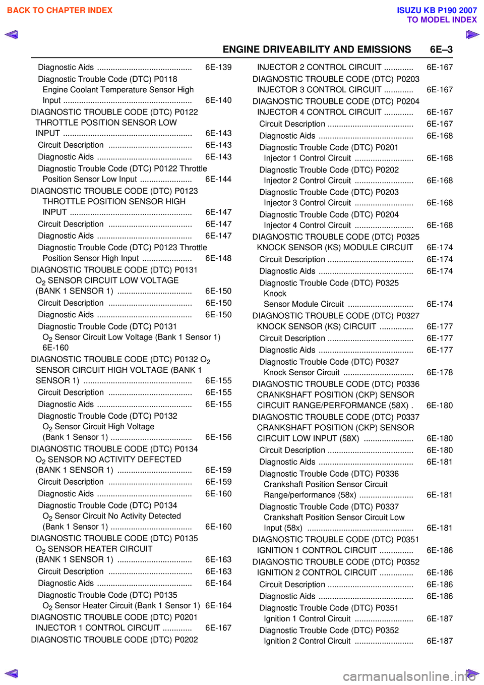
Diagnostic Aids .......................................... 6E-139
Diagnostic Trouble Code (DTC) P0118 Engine Coolant Temperature Sensor High
Input ......................................................... 6E-140
DIAGNOSTIC TROUBLE CODE (DTC) P0122 THROTTLE POSITION SENSOR LOW
INPUT ......................................................... 6E-143
Circuit Description ..................................... 6E-143
Diagnostic Aids .......................................... 6E-143
Diagnostic Trouble Code (DTC) P0122 Throttle Position Sensor Low Input ....................... 6E-144
DIAGNOSTIC TROUBLE CODE (DTC) P0123 THROTTLE POSITION SENSOR HIGH
INPUT ...................................................... 6E-147
Circuit Description ..................................... 6E-147
Diagnostic Aids .......................................... 6E-147
Diagnostic Trouble Code (DTC) P0123 Throttle Position Sensor High Input ...................... 6E-148
DIAGNOSTIC TROUBLE CODE (DTC) P0131 O
2 SENSOR CIRCUIT LOW VOLTAGE
(BANK 1 SENSOR 1) ................................. 6E-150
Circuit Description ..................................... 6E-150
Diagnostic Aids .......................................... 6E-150
Diagnostic Trouble Code (DTC) P0131 O
2 Sensor Circuit Low Voltage (Bank 1 Sensor 1)
6E-160
DIAGNOSTIC TROUBLE CODE (DTC) P0132 O
2
SENSOR CIRCUIT HIGH VOLTAGE (BANK 1
SENSOR 1) ................................................ 6E-155
Circuit Description ..................................... 6E-155
Diagnostic Aids .......................................... 6E-155
Diagnostic Trouble Code (DTC) P0132 O
2 Sensor Circuit High Voltage
(Bank 1 Sensor 1) .................................... 6E-156
DIAGNOSTIC TROUBLE CODE (DTC) P0134 O
2 SENSOR NO ACTIVITY DEFECTED
(BANK 1 SENSOR 1) ................................. 6E-159
Circuit Description ..................................... 6E-159
Diagnostic Aids .......................................... 6E-160
Diagnostic Trouble Code (DTC) P0134 O
2 Sensor Circuit No Activity Detected
(Bank 1 Sensor 1) .................................... 6E-160
DIAGNOSTIC TROUBLE CODE (DTC) P0135 O
2 SENSOR HEATER CIRCUIT
(BANK 1 SENSOR 1) ................................. 6E-163
Circuit Description ..................................... 6E-163
Diagnostic Aids .......................................... 6E-164
Diagnostic Trouble Code (DTC) P0135 O
2 Sensor Heater Circuit (Bank 1 Sensor 1) 6E-164
DIAGNOSTIC TROUBLE CODE (DTC) P0201 INJECTOR 1 CONTROL CIRCUIT ............. 6E-167
DIAGNOSTIC TROUBLE CODE (DTC) P0202 INJECTOR 2 CONTROL CIRCUIT ............. 6E-167
DIAGNOSTIC TROUBLE CODE (DTC) P0203 INJECTOR 3 CONTROL CIRCUIT ............. 6E-167
DIAGNOSTIC TROUBLE CODE (DTC) P0204 INJECTOR 4 CONTROL CIRCUIT ............. 6E-167
Circuit Description ...................................... 6E-167
Diagnostic Aids .......................................... 6E-168
Diagnostic Trouble Code (DTC) P0201 Injector 1 Control Circuit .......................... 6E-168
Diagnostic Trouble Code (DTC) P0202 Injector 2 Control Circuit .......................... 6E-168
Diagnostic Trouble Code (DTC) P0203 Injector 3 Control Circuit .......................... 6E-168
Diagnostic Trouble Code (DTC) P0204 Injector 4 Control Circuit .......................... 6E-168
DIAGNOSTIC TROUBLE CODE (DTC) P0325 KNOCK SENSOR (KS) MODULE CIRCUIT 6E-174
Circuit Description ...................................... 6E-174
Diagnostic Aids .......................................... 6E-174
Diagnostic Trouble Code (DTC) P0325 Knock
Sensor Module Circuit ............................. 6E-174
DIAGNOSTIC TROUBLE CODE (DTC) P0327 KNOCK SENSOR (KS) CIRCUIT ............... 6E-177
Circuit Description ...................................... 6E-177
Diagnostic Aids .......................................... 6E-177
Diagnostic Trouble Code (DTC) P0327 Knock Sensor Circuit ............................... 6E-178
DIAGNOSTIC TROUBLE CODE (DTC) P0336 CRANKSHAFT POSITION (CKP) SENSOR
CIRCUIT RANGE/PERFORMANCE (58X) . 6E-180
DIAGNOSTIC TROUBLE CODE (DTC) P0337 CRANKSHAFT POSITION (CKP) SENSOR
CIRCUIT LOW INPUT (58X) ...................... 6E-180
Circuit Description ...................................... 6E-180
Diagnostic Aids .......................................... 6E-181
Diagnostic Trouble Code (DTC) P0336 Crankshaft Position Sensor Circuit
Range/performance (58x) ........................ 6E-181
Diagnostic Trouble Code (DTC) P0337 Crankshaft Position Sensor Circuit Low
Input (58x) ............................................... 6E-181
DIAGNOSTIC TROUBLE CODE (DTC) P0351 IGNITION 1 CONTROL CIRCUIT ............... 6E-186
DIAGNOSTIC TROUBLE CODE (DTC) P0352 IGNITION 2 CONTROL CIRCUIT ............... 6E-186
Circuit Description ...................................... 6E-186
Diagnostic Aids .......................................... 6E-186
Diagnostic Trouble Code (DTC) P0351 Ignition 1 Control Circuit .......................... 6E-187
Diagnostic Trouble Code (DTC) P0352 Ignition 2 Control Circuit .......................... 6E-187
BACK TO CHAPTER INDEX
TO MODEL INDEX
ISUZU KB P190 2007