2007 ISUZU KB P190 low oil pressure
[x] Cancel search: low oil pressurePage 3751 of 6020
Exhaust System – V6 Page 6F – 3
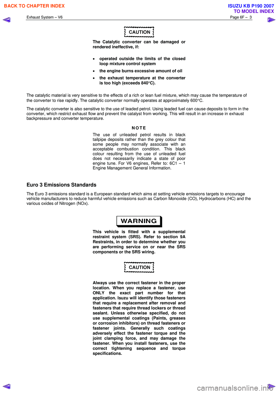
The Catalytic converter can be damaged or
rendered ineffective, if:
• operated outside the limits of the closed
loop mixture control system
• the engine burns excessive amount of oil
• the exhaust temperature at the converter
is too high (exceeds 840°C).
The catalytic material is very sensitive to the effects of a rich or lean fuel mixture, which may cause the temperature of
the converter to rise rapidly. The catalytic converter normally operates at approximately 600 °C.
The catalytic converter is also sensitive to the use of leaded petrol. Using leaded fuel can cause deposits to form in the
converter, which restrict exhaust flow and prevent the catalyst from working. This will result in an increase in exhaust
backpressure and converter temperature.
NOTE
The use of unleaded petrol results in black
tailpipe deposits rather than the grey colour that
some people may normally associate with an
acceptable combustion condition. This black
colour resulting from the use of unleaded fuel
does not necessarily indicate a state of poor
engine tune. For V6 engines, Refer to: 6C1 – 1
Engine Management General Information.
Euro 3 Emissions Standards
The Euro 3 emissions standard is a European standard which aims at setting vehicle emissions targets to encourage
vehicle manufacturers to reduce harmful vehicle emissions such as Carbon Monoxide (CO), Hydrocarbons (HC) and the
various oxides of Nitrogen (NOx).
This vehicle is fitted with a supplemental
restraint system (SRS). Refer to section 9A
Restraints, in order to determine whether you
are performing service on or near the SRS
components or the SRS wiring.
Always use the correct fastener in the proper
location. When you replace a fastener, use
ONLY the exact part number for that
application. Isuzu will identify those fasteners
that require a replacement after removal and
fasteners that require thread lockers or thread
sealant. Unless otherwise specified, do not
use supplemental coatings (Paints, greases
or corrosion inhibitors) on thread fasteners or
fastener joints. Generally such coatings
adversely effect the fastener torque and the
joint clamping force, and may damage the
fastener. When you install fasteners, use the
correct tightening sequence and torque
specifications.
BACK TO CHAPTER INDEX
TO MODEL INDEX
ISUZU KB P190 2007
Page 3765 of 6020
Automatic Transmission – 4L60E – General Information Page 7C1–5
Clean and Inspect
Do not use solvents on neoprene seals,
composition faced clutch plates or thrust
washers as damage to parts may occur.
After complete disassembly of a component, wash all metal parts in a clean solvent and dry with compressed air. Blow
oil passages out and check to make sure they are not obstructed, small passages should be checked with tag wire. All
parts should be inspected to determine if replacement is required.
Pay particular attention to the following:
• Inspect linkage and pivot points for excessive wear.
• Bearing and thrust surfaces of all parts should be checked for excessive wear and scoring.
• Check for broken seal rings, damaged ring lands and damaged threads.
• Inspect seals for damage.
• Mating surfaces of castings should be checked for burrs. Irregularities may be removed by lapping the surface with
emery paper laid on a flat surface, such as a piece of plate glass.
• Castings should be checked for cracks and porosity.
1.3 7C2 Automatic Transmission – 4L60E –
Electrical Diagnosis
For transmissions fitted to V6 engines, the electrical diagnosis is in this Section. A new electrical circuit and control
module has been introduced for automatic transmissions fitted to the V6 engines.
1.4 7C3 Automatic Transmission – 4L60E – Hydraulic and Mechanical Diagnosis
Information contained in 7C3 Automatic Transmission – 4L60E – Hydraulic and Mechanical Diagnosis will assist in the
diagnosis of the mechanical and hydraulic components in the 4L60E automatic transmission, while the transmission
remains installed on the vehicle.
Examples of the type of diagnostic information contained within this section are:
• transmission functional test,
• line pressure information,
• transmission fluid diagnosis,
• symptom diagnosis and
• shift speed charts.
1.5 7C4 Automatic Transmission – 4L60E –
On-vehicle Servicing
Information in 7C4 Automatic Transmission – 4L60E – On-vehicle Servicing covers transmission fluid level checking, as
well as specific information for servicing some components while the transmission remains installed on the vehicle. This
Section also covers the transmission removal and reinstallation to the vehicle.
BACK TO CHAPTER INDEX
TO MODEL INDEX
ISUZU KB P190 2007
Page 3768 of 6020
Automatic Transmission – 4L60E – General Information Page 7C1–8
2.4 System Protection Devices
Should 1st gear be selected and left in that range, the TCM will protect the engine from an over-speeding condition by
upshifting to 2nd gear at a pre-determined point. Similarly, the TCM provides high speed, downshift protection by
preventing a manual shift into 1st gear above pre-determined engine speeds.
Under severe operating conditions such as towing in high ambient temperatures, fluid temperatures can rise to a point
where lubrication breakdown can occur. In addition to having an oil cooler fitted to the vehicle, the 4L60E transmission is
also fitted with a transmission fluid temperature sensor located in the Transmission Range (TR) Pressure Switch
Assembly (PSA).
When fluid temperatures in excess of 135 °C are sensed, the torque converter clutch is applied as programmed, in 3rd or
4th gear. This action reduces further the fluid temperature during normal operation of the torque converter. While these
high fluid temperatures are sensed however, torque converter clutch apply is not available when the throttle opening is
above 50%.
Similarly, when the fluid temperature is below 29 °C, the TCM prevents torque converter clutch apply.
If a condition occurs, preventing electronic control of the transmission's functions, a 'Fail Safe' mode will default the
transmission to 3rd gear when either Drive or 3 is selected, applying also maximum line pressure. W hile in this mode, the
vehicle operator can still manually select 2, 1, Reverse, Park or Neutral, should the need arise.
2.5 Self Diagnosis
If any transmission operation controlled by the TCM begins to operate outside its pre-set parameters, the TCM has the
ability to store a range of diagnostic codes which can be accessed by the servicing technician, thereby localising the
problem.
2.6 TCM Sensors and Actuators
As indicated earlier, there are a number of sensors and switches providing input information for the TCM programming
that will allow the TCM to change the shift pattern, shift feel and torque converter clutch operation.
The TCM does this by comparing this input information with its predetermined values on shift pattern, fluid pressure
maps, shift duration parameters, extreme heat protection programming and adaptive controls.
In addition, each input signal and output actuator operation is also monitored and if outside its pre-set parameters, a
diagnostic code is logged for future reference by the servicing technician.
BACK TO CHAPTER INDEX
TO MODEL INDEX
ISUZU KB P190 2007
Page 3772 of 6020
Automatic Transmission – 4L60E – General Information Page 7C1–12
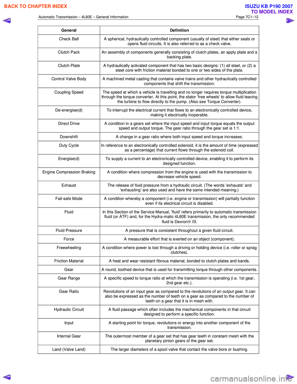
General Definition
Check Ball A spherical, hydraulically controlled component (usually of steel) that either seals or
opens fluid circuits. It is also referred to as a check valve.
Clutch Pack An assembly of components generally consisting of clutch plates, an apply plate and a
backing plate.
Clutch Plate A hydraulically activated component that has two basic designs: (1) all steel, or (2) a
steel core with friction material bonded to one or two sides of the plate.
Control Valve Body A machined metal casting that contains valve trains and other hydraulically controlled components that shift the transmission.
Coupling Speed The speed at which a vehicle is travelling and no longer requires torque multiplication through the torque converter. At this point, the stator 'free wheels' to allow fluid leaving
the turbine to flow directly to the pump. (Also see Torque Converter).
De-energise(d) To interrupt the electrical current that flows to an electronically controlled device,
making it electrically inoperable.
Direct Drive A condition in a gears set where the input speed and input torque equals the output
speed and output torque. The gear ratio through the gear set is 1:1.
Downshift A change in a gear ratio where both input speed and torque increases.
Duty Cycle In reference to an electronically controlled solenoid, it is the amount of time (expressed
as a percentage) that current flows through the solenoid coil.
Energise(d) To supply a current to an electronically controlled device, enabling it to perform its
designed function.
Engine Compression Braking A condition where compression from the engine is used with the transmission to decrease vehicle speed.
Exhaust The release of fluid pressure from a hydraulic circuit. (The words 'exhausts' and
'exhausting' are also used and have the same intended meaning.)
Fail-safe Mode A condition whereby a component (i.e. engine or transmission) will partially function even if its electrical circuit is disabled.
Fluid In this Section of the Service Manual, 'fluid' refers primarily to automatic transmission
fluid (or ATF) and, for the Hydra-matic 4L60E transmission, the only recommended
fluid is Dexron
III.
Fluid Pressure A pressure that is consistent throughout a given fluid circuit.
Force A measurable effort that is exerted on an object (component).
Freewheeling A condition where power is lost through a driving or holding device (i.e. roller or sprag
clutches).
Friction Material A heat and wear resistant fibrous material, bonded to clutch plates and bands.
Gear A round, toothed device that is used for transmitting torque through other components.
Gear Range A specific speed to torque ratio at which the transmission is operating (i.e. 1st gear,
2nd gear etc.).
Gear Ratio Revolutions of an input gear as compared to the revolutions of an output gear. It can
also be expressed as the number of teeth on a gear as compared to the number of
teeth on a gear that it is in mesh with.
Hydraulic Circuit A fluid passage which often includes the mechanical components in that circuit
designed to perform a specific function.
Input A starting point for torque, revolutions or energy into another component of the
transmission.
Internal Gear The outermost member of a gear set that has gear teeth in constant mesh with the
planetary pinion gears of the gear set.
Land (Valve Land) The larger diameters of a spool valve that contact the valve bore or bushing.
BACK TO CHAPTER INDEX
TO MODEL INDEX
ISUZU KB P190 2007
Page 3819 of 6020
Automatic Transmission – 4L60E – Electrical Diagnosis Page 7C2–33
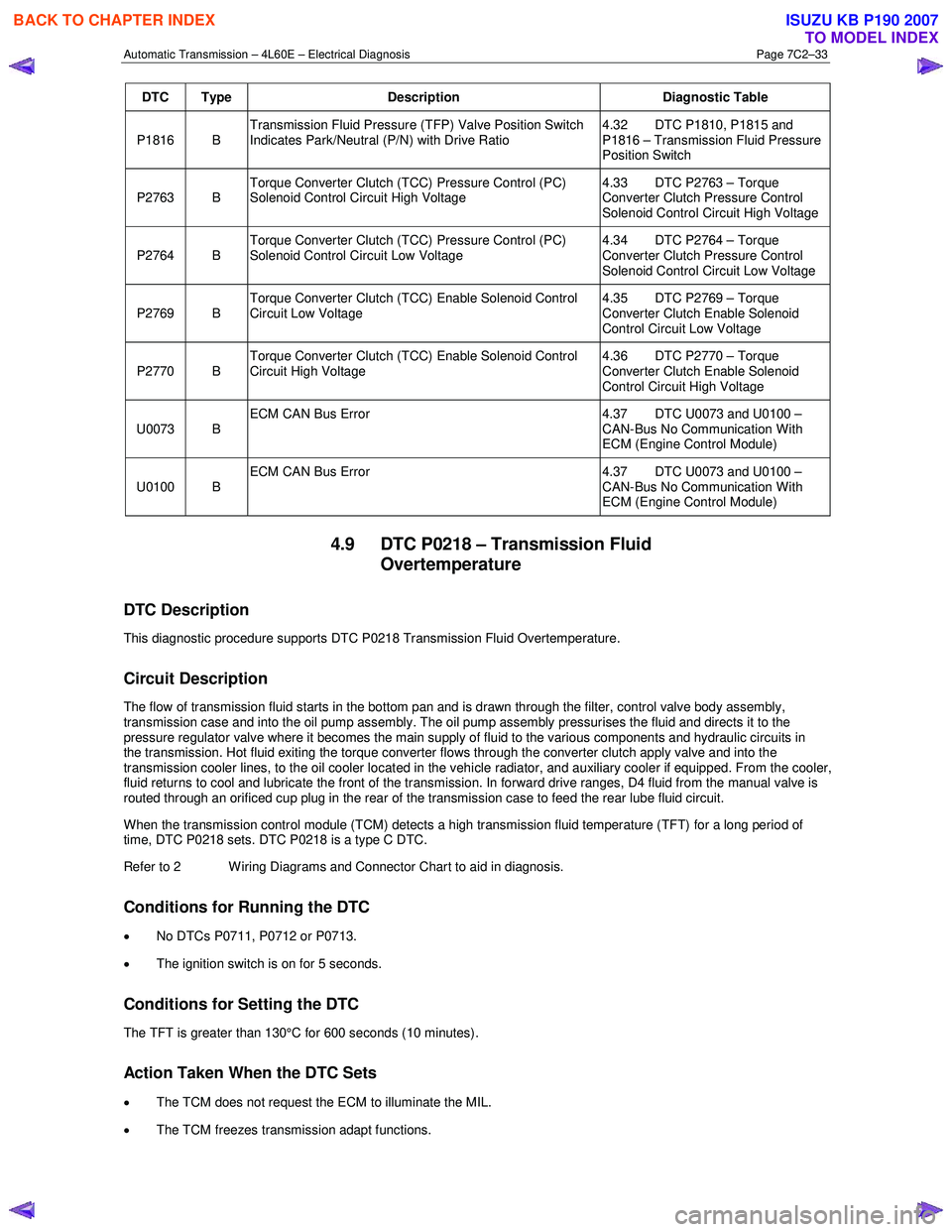
DTC Type Description Diagnostic Table
P1816 B Transmission Fluid Pressure (TFP) Valve Position Switch
Indicates Park/Neutral (P/N) with Drive Ratio 4.32 DTC P1810, P1815 and
P1816 – Transmission Fluid Pressure
Position Switch
P2763 B Torque Converter Clutch (TCC) Pressure Control (PC)
Solenoid Control Circuit High Voltage 4.33 DTC P2763 – Torque
Converter Clutch Pressure Control
Solenoid Control Circuit High Voltage
P2764 B Torque Converter Clutch (TCC) Pressure Control (PC)
Solenoid Control Circuit Low Voltage 4.34 DTC P2764 – Torque
Converter Clutch Pressure Control
Solenoid Control Circuit Low Voltage
P2769 B Torque Converter Clutch (TCC) Enable Solenoid Control
Circuit Low Voltage 4.35 DTC P2769 – Torque
Converter Clutch Enable Solenoid
Control Circuit Low Voltage
P2770 B Torque Converter Clutch (TCC) Enable Solenoid Control
Circuit High Voltage 4.36 DTC P2770 – Torque
Converter Clutch Enable Solenoid
Control Circuit High Voltage
U0073 B ECM CAN Bus Error
4.37 DTC U0073 and U0100 –
CAN-Bus No Communication With
ECM (Engine Control Module)
U0100 B ECM CAN Bus Error
4.37 DTC U0073 and U0100 –
CAN-Bus No Communication With
ECM (Engine Control Module)
4.9 DTC P0218 – Transmission Fluid Overtemperature
DTC Description
This diagnostic procedure supports DTC P0218 Transmission Fluid Overtemperature.
Circuit Description
The flow of transmission fluid starts in the bottom pan and is drawn through the filter, control valve body assembly,
transmission case and into the oil pump assembly. The oil pump assembly pressurises the fluid and directs it to the
pressure regulator valve where it becomes the main supply of fluid to the various components and hydraulic circuits in
the transmission. Hot fluid exiting the torque converter flows through the converter clutch apply valve and into the
transmission cooler lines, to the oil cooler located in the vehicle radiator, and auxiliary cooler if equipped. From the cooler ,
fluid returns to cool and lubricate the front of the transmission. In forward drive ranges, D4 fluid from the manual valve is
routed through an orificed cup plug in the rear of the transmission case to feed the rear lube fluid circuit.
When the transmission control module (TCM) detects a high transmission fluid temperature (TFT) for a long period of
time, DTC P0218 sets. DTC P0218 is a type C DTC.
Refer to 2 W iring Diagrams and Connector Chart to aid in diagnosis.
Conditions for Running the DTC
• No DTCs P0711, P0712 or P0713.
• The ignition switch is on for 5 seconds.
Conditions for Setting the DTC
The TFT is greater than 130°C for 600 seconds (10 minutes).
Action Taken When the DTC Sets
•
The TCM does not request the ECM to illuminate the MIL.
• The TCM freezes transmission adapt functions.
BACK TO CHAPTER INDEX
TO MODEL INDEX
ISUZU KB P190 2007
Page 3843 of 6020
Automatic Transmission – 4L60E – Electrical Diagnosis Page 7C2–57
Step Action Yes No
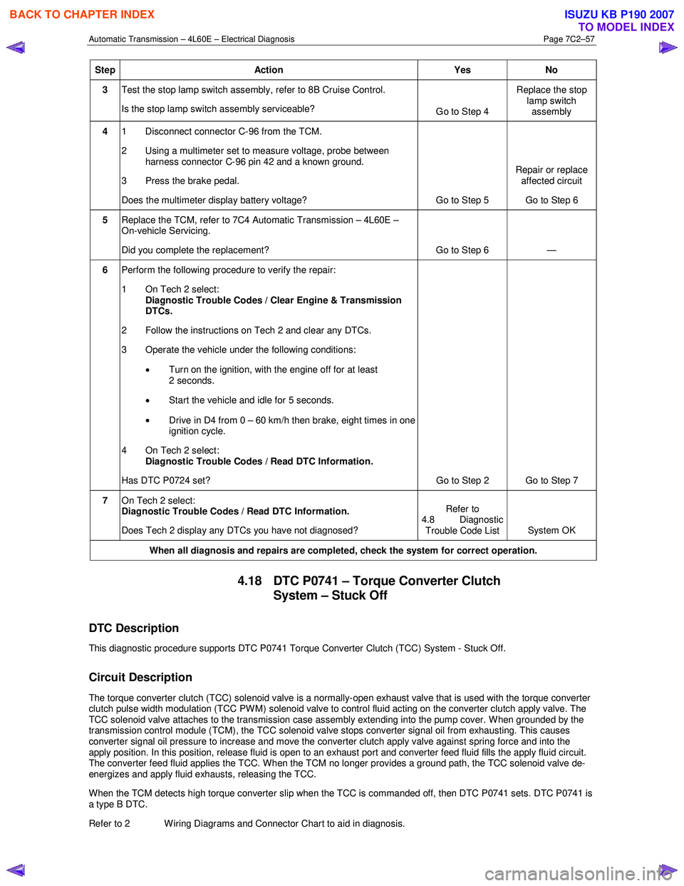
3 Test the stop lamp switch assembly, refer to 8B Cruise Control.
Is the stop lamp switch assembly serviceable? Go to Step 4 Replace the stop
lamp switch assembly
4 1 Disconnect connector C-96 from the TCM.
2 Using a multimeter set to measure voltage, probe between harness connector C-96 pin 42 and a known ground.
3 Press the brake pedal.
Does the multimeter display battery voltage? Go to Step 5 Repair or replace
affected circuit
Go to Step 6
5 Replace the TCM, refer to 7C4 Automatic Transmission – 4L60E –
On-vehicle Servicing.
Did you complete the replacement? Go to Step 6 —
6 Perform the following procedure to verify the repair:
1 On Tech 2 select: Diagnostic Trouble Codes / Clear Engine & Transmission
DTCs.
2 Follow the instructions on Tech 2 and clear any DTCs.
3 Operate the vehicle under the following conditions:
• Turn on the ignition, with the engine off for at least
2 seconds.
• Start the vehicle and idle for 5 seconds.
• Drive in D4 from 0 – 60 km/h then brake, eight times in one
ignition cycle.
4 On Tech 2 select:
Diagnostic Trouble Codes / Read DTC Information.
Has DTC P0724 set? Go to Step 2 Go to Step 7
7 On Tech 2 select:
Diagnostic Trouble Codes / Read DTC Information.
Does Tech 2 display any DTCs you have not diagnosed? Refer to
4.8 Diagnostic Trouble Code List System OK
When all diagnosis and repairs are completed, check the
system for correct operation.
4.18 DTC P0741 – Torque Converter Clutch
System – Stuck Off
DTC Description
This diagnostic procedure supports DTC P0741 Torque Converter Clutch (TCC) System - Stuck Off.
Circuit Description
The torque converter clutch (TCC) solenoid valve is a normally-open exhaust valve that is used with the torque converter
clutch pulse width modulation (TCC PWM) solenoid valve to control fluid acting on the converter clutch apply valve. The
TCC solenoid valve attaches to the transmission case assembly extending into the pump cover. W hen grounded by the
transmission control module (TCM), the TCC solenoid valve stops converter signal oil from exhausting. This causes
converter signal oil pressure to increase and move the converter clutch apply valve against spring force and into the
apply position. In this position, release fluid is open to an exhaust port and converter feed fluid fills the apply fluid circu it.
The converter feed fluid applies the TCC. When the TCM no longer provides a ground path, the TCC solenoid valve de-
energizes and apply fluid exhausts, releasing the TCC.
When the TCM detects high torque converter slip when the TCC is commanded off, then DTC P0741 sets. DTC P0741 is
a type B DTC.
Refer to 2 W iring Diagrams and Connector Chart to aid in diagnosis.
BACK TO CHAPTER INDEX
TO MODEL INDEX
ISUZU KB P190 2007
Page 3846 of 6020
Automatic Transmission – 4L60E – Electrical Diagnosis Page 7C2–60
Step Action Yes No
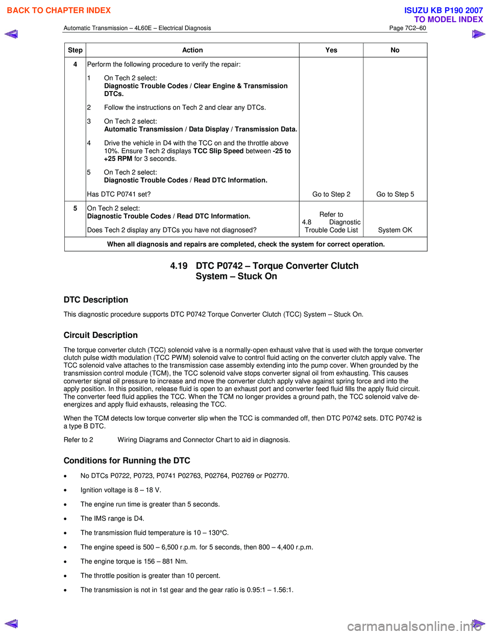
4 Perform the following procedure to verify the repair:
1 On Tech 2 select: Diagnostic Trouble Codes / Clear Engine & Transmission
DTCs.
2 Follow the instructions on Tech 2 and clear any DTCs.
3 On Tech 2 select: Automatic Transmission / Data Display / Transmission Data.
4 Drive the vehicle in D4 with the TCC on and the throttle above 10%. Ensure Tech 2 displays TCC Slip Speed between -25 to
+25 RPM for 3 seconds.
5 On Tech 2 select:
Diagnostic Trouble Codes / Read DTC Information.
Has DTC P0741 set? Go to Step 2 Go to Step 5
5 On Tech 2 select:
Diagnostic Trouble Codes / Read DTC Information.
Does Tech 2 display any DTCs you have not diagnosed? Refer to
4.8 Diagnostic Trouble Code List System OK
When all diagnosis and repairs are completed, check the system for correct operation.
4.19 DTC P0742 – Torque Converter Clutch
System – Stuck On
DTC Description
This diagnostic procedure supports DTC P0742 Torque Converter Clutch (TCC) System – Stuck On.
Circuit Description
The torque converter clutch (TCC) solenoid valve is a normally-open exhaust valve that is used with the torque converter
clutch pulse width modulation (TCC PWM) solenoid valve to control fluid acting on the converter clutch apply valve. The
TCC solenoid valve attaches to the transmission case assembly extending into the pump cover. W hen grounded by the
transmission control module (TCM), the TCC solenoid valve stops converter signal oil from exhausting. This causes
converter signal oil pressure to increase and move the converter clutch apply valve against spring force and into the
apply position. In this position, release fluid is open to an exhaust port and converter feed fluid fills the apply fluid circu it.
The converter feed fluid applies the TCC. When the TCM no longer provides a ground path, the TCC solenoid valve de-
energizes and apply fluid exhausts, releasing the TCC.
W hen the TCM detects low torque converter slip when the TCC is commanded off, then DTC P0742 sets. DTC P0742 is
a type B DTC.
Refer to 2 W iring Diagrams and Connector Chart to aid in diagnosis.
Conditions for Running the DTC
• No DTCs P0722, P0723, P0741 P02763, P02764, P02769 or P02770.
• Ignition voltage is 8 – 18 V.
• The engine run time is greater than 5 seconds.
• The IMS range is D4.
• The transmission fluid temperature is 10 – 130°C.
• The engine speed is 500 – 6,500 r.p.m. for 5 seconds, then 800 – 4,400 r.p.m.
• The engine torque is 156 – 881 Nm.
• The throttle position is greater than 10 percent.
• The transmission is not in 1st gear and the gear ratio is 0.95:1 – 1.56:1.
BACK TO CHAPTER INDEX
TO MODEL INDEX
ISUZU KB P190 2007
Page 3867 of 6020
Automatic Transmission – 4L60E – Electrical Diagnosis Page 7C2–81
Action Taken When the DTC Sets
• The TCM requests the ECM to illuminate the MIL during the second consecutive trip in which the conditions for
setting the DTC are met.
• The TCM commands maximum line pressure.
• The TCM freezes transmission adaptive functions.
• The TCM inhibits TCC.
• The TCM inhibits 4th gear if in hot mode.
• At the time of the first failure, the TCM records the operating conditions when the conditions for setting the DTC are
met. The TCM stores this information as a Failure Record.
• At the time of the second failure, the ECM records the operating conditions when the conditions for setting the DTC
are met. The ECM stores this information as a Freeze Frame.
• The TCM stores DTC P0894 in TCM history during the second consecutive trip in which the conditions for setting
the DTC are met.
Conditions for Clearing the DTC
• The ECM turns off the MIL after the fourth consecutive drive trip in which the TCM does not send a MIL illumination
request.
• Tech 2 can clear the DTC.
• The TCM clears the DTC from TCM history if the vehicle completes 40 warm-up cycles without a non-emission
related diagnostic fault occurring.
• The TCM cancels the DTC default actions when the ignition is off long enough to power down the TCM.
Diagnostic Aids
•
Bronze material found in the transmission oil pan may indicate stator shaft bushing wear. If bushing wear is
suspected, inspect the stator shaft and the input, turbine, shaft for damage.
• Perform the Torque Converter Diagnosis Procedure, refer to 7C3 Automatic Transmission – 4L60E – Hydraulic and
Mechanical Diagnosis.
Test Description
The following numbers refer to the step numbers in the diagnostic table:
3 Checks the torque converter for slippage while in a commanded lock-up state.
4-12 Checks the mechanical components that cause the DTC and their state.
13 W hen the TAP cells are cleared the TCM needs to relearn the TAP cells for the transmission. As such, when the vehicle is first driven, the shifts may be harsh. The transmission shifts should become smoother the more the
vehicle is driven until the TCM has relearned all TAP cells.
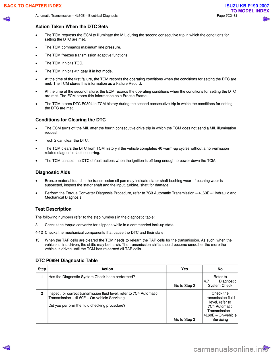
DTC P0894 Diagnostic Table
Step Action Yes No
1 Has the Diagnostic System Check been performed?
Go to Step 2 Refer to
4.7 Diagnostic System Check
2 Inspect for correct transmission fluid level, refer to 7C4 Automatic
Transmission – 4L60E – On-vehicle Servicing.
Did you perform the fluid checking procedure?
Go to Step 3 Check the
transmission fluid level, refer to
7C4 Automatic
Transmission –
4L60E – On-vehicle Servicing
BACK TO CHAPTER INDEX
TO MODEL INDEX
ISUZU KB P190 2007