2007 ISUZU KB P190 low oil pressure
[x] Cancel search: low oil pressurePage 3198 of 6020
Engine Cooling – V6 Engine Page 6B1–63
4.5 Problems Not Requiring Disassembly of
Cooling System
1 Large obstructions blocking radiator or condenser airflow.
• Auxiliary oil coolers
• License plate
• Obstruction of radiator grille, for example, driving lights or mud
2 Loose, damaged or missing air chute side panels.
3 Missing or damaged air baffle.
4 Cracked or loose coolant recovery system hose.
5 Leaking heater component such as the heater core or water valve.
4.6 Problems Requiring Disassembly of Cooling System
1 Damaged cooling fan or faulty motor operation.
2 Pressure test cooling system.
3 Defective coolant pump.
• Eroded or broken impeller vanes
• Failed bearing or seal – check for shaft or bearing end play
4 Internally blocked radiator core.
5 Obstruction of coolant recovery system.
6 Internal system leaks.
• Head gaskets
• Cracked cylinder block
• Engine front cover
• Intake manifold gaskets
7 Blocked coolant passages in cylinder heads or block – remove cylinder heads and check.
4.7 Black Light and Dye Leak Diagnosis Method
It is strongly recommended that this diagnostic method be used to diagnose fluid leaks. This method is a proven and
reliable method that identifies the specific leak source.
The black light kit can be used for the leak detection of a number of fluids, when used with the appropriate tracer dye.
Examples are: Coolant, Engine Oil, Automatic Transmission Fluid and Air Conditioning Refrigerant (R134A).
The following is a summary of the steps involved in detecting a cooling system fluid leak using black light and dye:
1 Pour specified amount of dye into the cooling system via the coolant filler cap on the outlet housing. Refer 3.1 Service Notes in this Section.
2 Road test the vehicle under normal operating conditions.
3 Direct the light towards the suspect area. The fluid leak will appear as a brightly coloured path leading from the source.
4 Repair fluid leak and recheck to ensure that leak has been rectified.
5 Refer to the manufacturer’s directions when using this method.
BACK TO CHAPTER INDEX
TO MODEL INDEX
ISUZU KB P190 2007
Page 3205 of 6020
Fuel System – V6 Page 6C – 3
1 General Information
Description
Fuel is injected into the engine by separate fuel injectors that are mounted in the intake manifold (common chamber).
Fuel is supplied to the injectors under pressure from the fuel tank through the fuel lines and the fuel rail, which is
attached to the top of the common chamber.
A fuel pressure control valve is installed on the fuel rail to maintain fuel line pressure across the injectors under all
operating conditions. Fuel pressure is maintained by controlling the amount of fuel that is supplied from the fuel tank,
based on the demand of the engine via the engine control module (ECM).
Two interchangeable “O” rings are used on the fuel injector and must be replaced when the injectors are removed.
The Multiport Fuel Injection system utilizes an injection system where the injectors turn on at every crankshaft revolution.
The ECM controls the injector on time so that the correct amount of fuel is metered depending on driving conditions.
The V6 engine is designed to use only unleaded petrol.
Unleaded petrol must be used for correct emission control system operation and its use will also minimize spark plug
fouling and extend engine oil life.
Using leaded petrol can damage the emission control system and could void the vehicle warranty. All vehicles are
equipped with an Evaporative Emission Control System. The purpose of the system is to minimize the escape of fuel
vapours into the atmosphere.
Service Precautions
• Use extreme care when working on the fuel system and follow all safety precautions.
• W hen working on the fuel system, disconnect the battery ground cable except for tests where battery voltage is
required.
• Always keep a dry chemical (class B) fire extinguisher near the work area.
• Relace all fuel lines and fittings with the same type of line and fitting as those removed.
• Clean and inspect “O” rings carefully and replace if required.
• Always depressurize the fuel lines before servicing any fuel system components.
• Do not attempt any repairs on the fuel system until, all warnings and instructions, relating to that repair have been
read and ensure all notices and cautions are adhered to.
• Do not allow any naked frames or sparks near the work area when working on the fuel system.
• If draining of the fuel system is required, this should be done in a well ventilated area.
• Protect the fuel lines and associated parts from thermal damage, spattering when welding.
BACK TO CHAPTER INDEX
TO MODEL INDEX
ISUZU KB P190 2007
Page 3214 of 6020
Fuel System – V6 Page 6C – 12
A small amount of fuel may be released when
pressing on the Schrader valve. Cover the
fitting with a shop towel to absorb any fuel
spillage before removing the Schrader valve
sealing cap. Place the soiled towel in an
approved container for disposal.
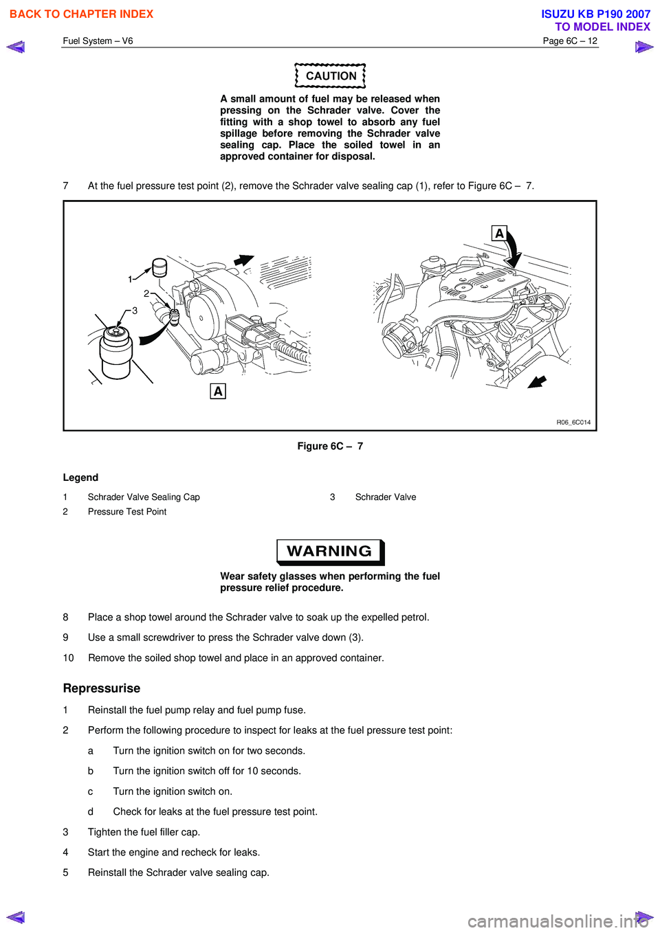
7 At the fuel pressure test point (2), remove the Schrader valve sealing cap (1), refer to Figure 6C – 7.
Figure 6C – 7
Legend
1 Schrader Valve Sealing Cap
2 Pressure Test Point 3 Schrader Valve
Wear safety glasses when performing the fuel
pressure relief procedure.
8 Place a shop towel around the Schrader valve to soak up the expelled petrol.
9 Use a small screwdriver to press the Schrader valve down (3).
10 Remove the soiled shop towel and place in an approved container.
Repressurise
1 Reinstall the fuel pump relay and fuel pump fuse.
2 Perform the following procedure to inspect for leaks at the fuel pressure test point: a Turn the ignition switch on for two seconds.
b Turn the ignition switch off for 10 seconds.
c Turn the ignition switch on.
d Check for leaks at the fuel pressure test point.
3 Tighten the fuel filler cap.
4 Start the engine and recheck for leaks.
5 Reinstall the Schrader valve sealing cap.
BACK TO CHAPTER INDEX
TO MODEL INDEX
ISUZU KB P190 2007
Page 3244 of 6020
Engine Management – V6 – General Information Page 6C1-1–2
3.9 Serial Data Communication System ................................................................................................................... 17
3.10 Self Diagnostics System ..................................................................................................................................... 17
3.11 Service Programming System ..................................................................................................... ....................... 17
3.12 Immobiliser System ............................................................................................................................................. 18
4 Component Description and Operation ............................................................................................ .19
4.1 A/C Refrigerant Pressure Sensor ....................................................................................................................... 19
4.2 Brake Pedal Switch Assembly ............................................................................................................................ 19
Stop Lamp and Initial Brake Apply Switch ....................................................................................... ................. 19
Stop Lamp Switch ............................................................................................................................................ 19
Initial Brake Apply Switch ..................................................................................................... ............................ 19
4.3 Barometric Pressure Sensor..................................................................................................... .......................... 20
4.4 Camshaft Position Sensor .................................................................................................................................. 20
4.5 Crankshaft Position Sensor ................................................................................................................................ 21
4.6 Clutch Pedal Switch Assembly – Manual Vehicles Only ............................................................................ ...... 22
4.7 Engine Control Module........................................................................................................................................ 22
4.8 Engine Coolant Temperature Sensor .............................................................................................. ................... 23
4.9 Electric Cooling Fans .......................................................................................................................................... 23
4.10 Engine Oil Level and Temperature Sensor ........................................................................................ ................ 24
Engine Oil Temperature Sensor ......................................................................................................................... 24
Engine Oil Level Sensor ...................................................................................................................................... 25
4.11 Engine Oil Pressure Sensor..................................................................................................... ........................... 25
4.12 Fuel Injectors........................................................................................................................................................ 26
4.13 Fuel Rail Assembly ............................................................................................................. ................................. 27
4.14 Heated Oxygen Sensors .......................................................................................................... ............................ 27
LSF 4.2 Two-step Planar Heated Oxygen Sensors .................................................................................. ......... 27
LSU 4.2 Wide-band Planar Heated Oxygen Sensors ................................................................................. ....... 29
4.15 Ignition Coil and Spark Plug ............................................................................................................................... 31
4.16 Intake Air Temperature Sensor .................................................................................................. ......................... 32
4.17 Knock Sensor ....................................................................................................................................................... 32
4.18 Mass Air Flow Sensor........................................................................................................... ............................... 33
Air Intake System ................................................................................................................................................. 33
Mass Air Flow Sensor........................................................................................................... ............................... 33
Construction ..................................................................................................................................................... 34
Operation ......................................................................................................................................................... 34
5 Abbreviations and Glossary of Terms ............................................................................................ ...35
BACK TO CHAPTER INDEX
TO MODEL INDEX
ISUZU KB P190 2007
Page 3251 of 6020
Engine Management – V6 – General Information Page 6C1-1–9
3 System Operation
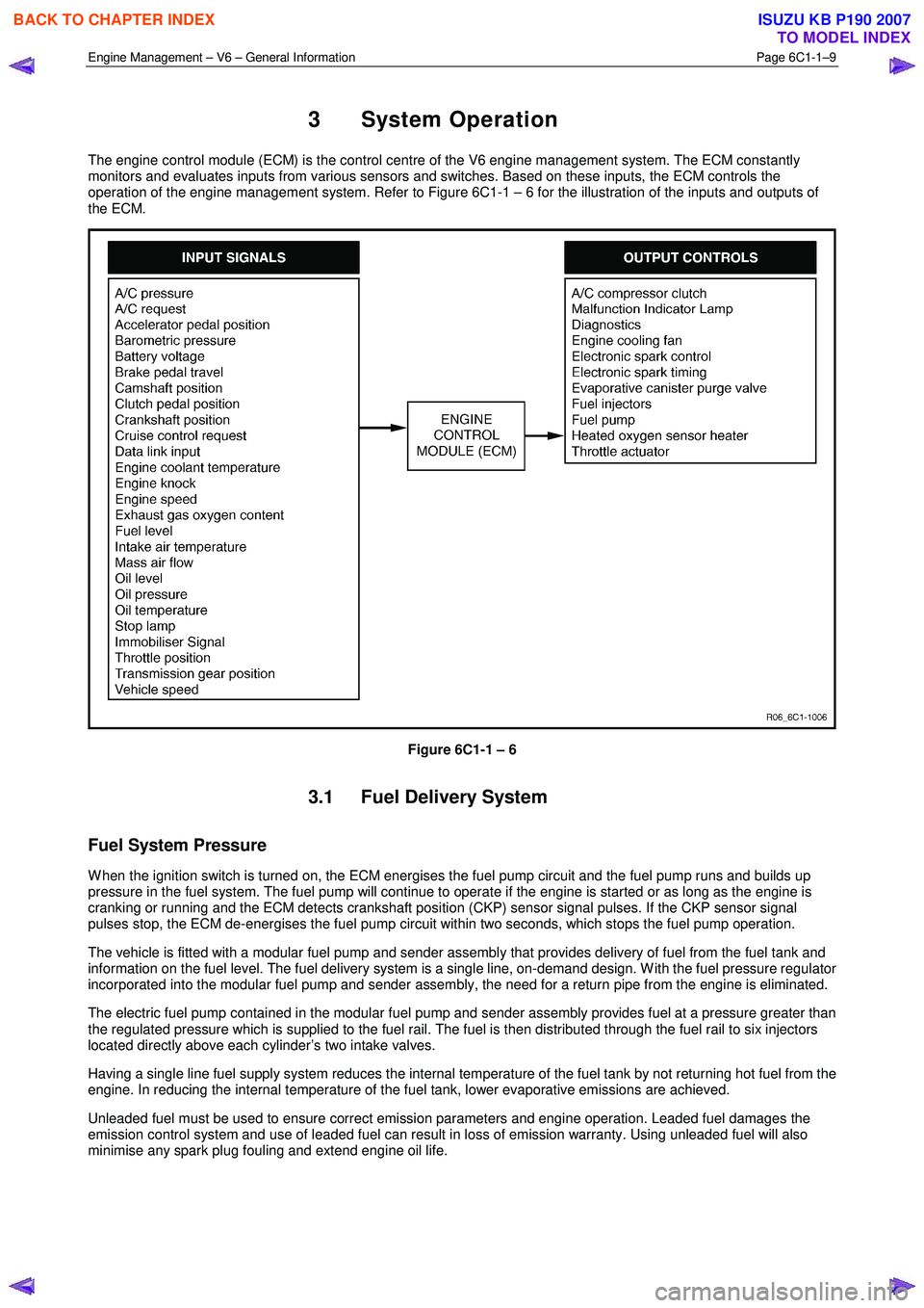
The engine control module (ECM) is the control centre of the V6 engine management system. The ECM constantly
monitors and evaluates inputs from various sensors and switches. Based on these inputs, the ECM controls the
operation of the engine management system. Refer to Figure 6C1-1 – 6 for the illustration of the inputs and outputs of
the ECM.
Figure 6C1-1 – 6
3.1 Fuel Delivery System
Fuel System Pressure
W hen the ignition switch is turned on, the ECM energises the fuel pump circuit and the fuel pump runs and builds up
pressure in the fuel system. The fuel pump will continue to operate if the engine is started or as long as the engine is
cranking or running and the ECM detects crankshaft position (CKP) sensor signal pulses. If the CKP sensor signal
pulses stop, the ECM de-energises the fuel pump circuit within two seconds, which stops the fuel pump operation.
The vehicle is fitted with a modular fuel pump and sender assembly that provides delivery of fuel from the fuel tank and
information on the fuel level. The fuel delivery system is a single line, on-demand design. W ith the fuel pressure regulator
incorporated into the modular fuel pump and sender assembly, the need for a return pipe from the engine is eliminated.
The electric fuel pump contained in the modular fuel pump and sender assembly provides fuel at a pressure greater than
the regulated pressure which is supplied to the fuel rail. The fuel is then distributed through the fuel rail to six injectors
located directly above each cylinder’s two intake valves.
Having a single line fuel supply system reduces the internal temperature of the fuel tank by not returning hot fuel from the
engine. In reducing the internal temperature of the fuel tank, lower evaporative emissions are achieved.
Unleaded fuel must be used to ensure correct emission parameters and engine operation. Leaded fuel damages the
emission control system and use of leaded fuel can result in loss of emission warranty. Using unleaded fuel will also
minimise any spark plug fouling and extend engine oil life.
BACK TO CHAPTER INDEX
TO MODEL INDEX
ISUZU KB P190 2007
Page 3267 of 6020
Engine Management – V6 – General Information Page 6C1-1–25
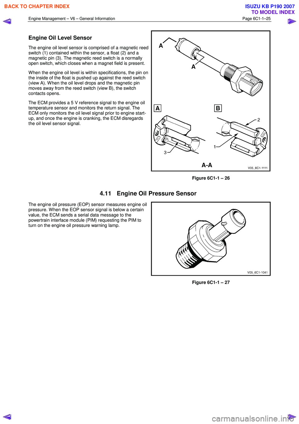
Engine Oil Level Sensor
The engine oil level sensor is comprised of a magnetic reed
switch (1) contained within the sensor, a float (2) and a
magnetic pin (3). The magnetic reed switch is a normally
open switch, which closes when a magnet field is present.
W hen the engine oil level is within specifications, the pin on
the inside of the float is pushed up against the reed switch
(view A). W hen the oil level drops and the magnetic pin
moves away from the reed switch (view B), the switch
contacts opens.
The ECM provides a 5 V reference signal to the engine oil
temperature sensor and monitors the return signal. The
ECM only monitors the oil level signal prior to engine start-
up, and once the engine is cranking, the ECM disregards
the oil level sensor signal.
Figure 6C1-1 – 26
4.11 Engine Oil Pressure Sensor
The engine oil pressure (EOP) sensor measures engine oil
pressure. W hen the EOP sensor signal is below a certain
value, the ECM sends a serial data message to the
powertrain interface module (PIM) requesting the PIM to
turn on the engine oil pressure warning lamp.
Figure 6C1-1 – 27
BACK TO CHAPTER INDEX
TO MODEL INDEX
ISUZU KB P190 2007
Page 3291 of 6020
Engine Management – V6 – Diagnostics Page 6C1-2–13
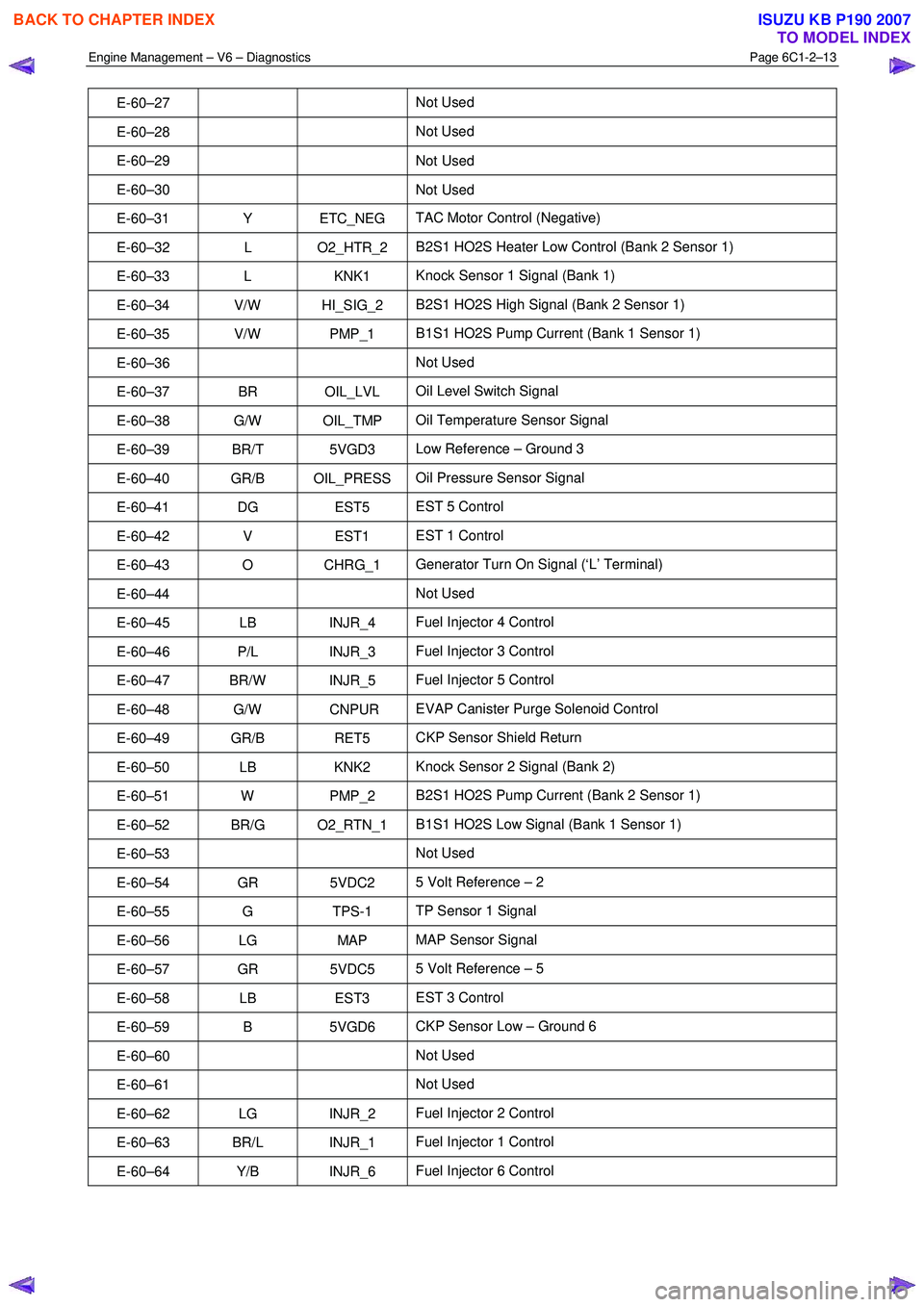
E-60–27 Not Used
E-60–28 Not Used
E-60–29 Not
Used
E-60–30 Not Used
E-60–31 Y ETC_NEG TAC Motor Control (Negative)
E-60–32 L O2_HTR_2 B2S1 HO2S Heater Low Control (Bank 2 Sensor 1)
E-60–33 L KNK1 Knock Sensor 1 Signal (Bank 1)
E-60–34 V/W HI_SIG_2 B2S1 HO2S High Signal (Bank 2 Sensor 1)
E-60–35 V/W PMP_1 B1S1 HO2S Pump Current (Bank 1 Sensor 1)
E-60–36 Not Used
E-60–37 BR OIL_LVL Oil Level Switch Signal
E-60–38 G/W OIL_TMP Oil Temperature Sensor Signal
E-60–39 BR/T 5VGD3 Low Reference – Ground 3
E-60–40 GR/B OIL_PRESS Oil Pressure Sensor Signal
E-60–41 DG EST5 EST 5 Control
E-60–42 V EST1 EST 1 Control
E-60–43 O CHRG_1 Generator Turn On Signal (‘L’ Terminal)
E-60–44 Not Used
E-60–45 LB INJR_4 Fuel Injector 4 Control
E-60–46 P/L INJR_3 Fuel Injector 3 Control
E-60–47 BR/W INJR_5 Fuel Injector 5 Control
E-60–48 G/W CNPUR EVAP Canister Purge Solenoid Control
E-60–49 GR/B RET5 CKP Sensor Shield Return
E-60–50 LB KNK2 Knock Sensor 2 Signal (Bank 2)
E-60–51 W PMP_2 B2S1 HO2S Pump Current (Bank 2 Sensor 1)
E-60–52 BR/G O2_RTN_1 B1S1 HO2S Low Signal (Bank 1 Sensor 1)
E-60–53 Not Used
E-60–54 GR 5VDC2 5 Volt Reference – 2
E-60–55 G TPS-1 TP Sensor 1 Signal
E-60–56 LG MAP MAP Sensor Signal
E-60–57 GR 5VDC5 5 Volt Reference – 5
E-60–58 LB EST3 EST 3 Control
E-60–59 B 5VGD6 CKP Sensor Low – Ground 6
E-60–60 Not Used
E-60–61 Not Used
E-60–62 LG INJR_2 Fuel Injector 2 Control
E-60–63 BR/L INJR_1 Fuel Injector 1 Control
E-60–64 Y/B INJR_6 Fuel Injector 6 Control
BACK TO CHAPTER INDEX
TO MODEL INDEX
ISUZU KB P190 2007
Page 3303 of 6020
Engine Management – V6 – Diagnostics Page 6C1-2–25
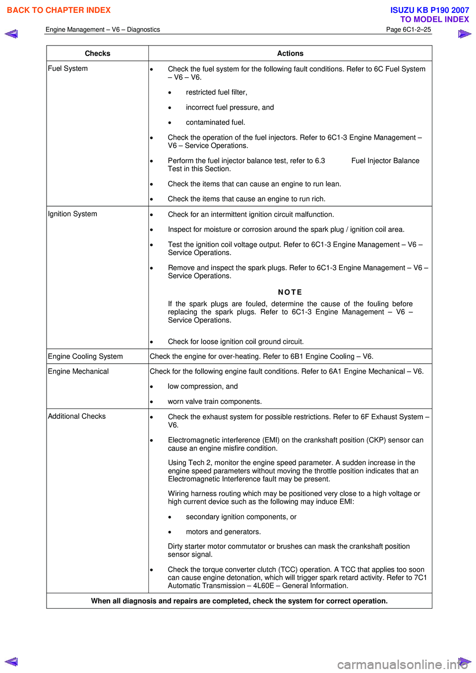
Checks Actions
Fuel System
• Check the fuel system for the following fault conditions. Refer to 6C Fuel System
– V6 – V6.
• restricted fuel filter,
• incorrect fuel pressure, and
• contaminated fuel.
• Check the operation of the fuel injectors. Refer to 6C1-3 Engine Management –
V6 – Service Operations.
• Perform the fuel injector balance test, refer to 6.3 Fuel Injector Balance
Test in this Section.
• Check the items that can cause an engine to run lean.
• Check the items that cause an engine to run rich.
Ignition System
• Check for an intermittent ignition circuit malfunction.
• Inspect for moisture or corrosion around the spark plug / ignition coil area.
• Test the ignition coil voltage output. Refer to 6C1-3 Engine Management – V6 –
Service Operations.
• Remove and inspect the spark plugs. Refer to 6C1-3 Engine Management – V6 –
Service Operations.
NOTE
If the spark plugs are fouled, determine the cause of the fouling before
replacing the spark plugs. Refer to 6C1-3 Engine Management – V6 –
Service Operations.
• Check for loose ignition coil ground circuit.
Engine Cooling System Check the engine for over-heating. Refer to 6B1 Engine Cooling – V6.
Engine Mechanical Check for the following engine fault conditions. Refer to 6A1 Engine Mechanical – V6.
• low compression, and
• worn valve train components.
Additional Checks
• Check the exhaust system for possible restrictions. Refer to 6F Exhaust System –
V6.
• Electromagnetic interference (EMI) on the crankshaft position (CKP) sensor can
cause an engine misfire condition.
Using Tech 2, monitor the engine speed parameter. A sudden increase in the engine speed parameters without moving the throttle position indicates that an
Electromagnetic Interference fault may be present.
W iring harness routing which may be positioned very close to a high voltage or high current device such as the following may induce EMI:
• secondary ignition components, or
• motors and generators.
Dirty starter motor commutator or brushes can mask the crankshaft position sensor signal.
• Check the torque converter clutch (TCC) operation. A TCC that applies too soon
can cause engine detonation, which will trigger spark retard activity. Refer to 7C1
Automatic Transmission – 4L60E – General Information.
When all diagnosis and repairs are completed, check the system for correct operation.
BACK TO CHAPTER INDEX
TO MODEL INDEX
ISUZU KB P190 2007