2007 ISUZU KB P190 low oil pressure
[x] Cancel search: low oil pressurePage 2818 of 6020
Engine Mechanical – V6 Page 6A1–41
Page 6A1–41
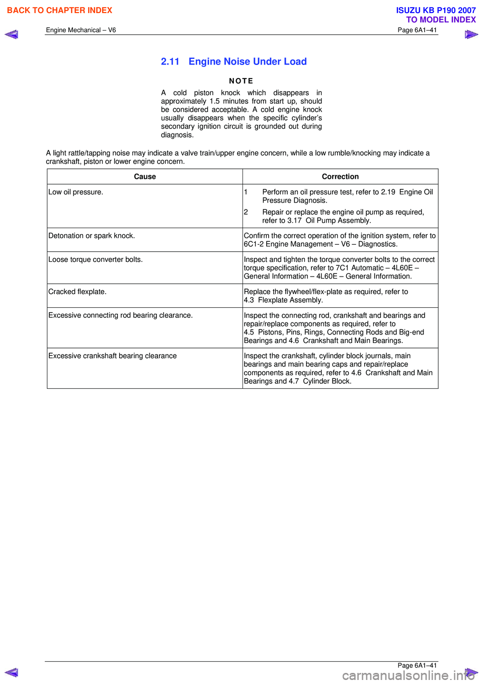
2.11 Engine Noise Under Load
NOTE
A cold piston knock which disappears in
approximately 1.5 minutes from start up, should
be considered acceptable. A cold engine knock
usually disappears when t he specific cylinder’s
secondary ignition circuit is grounded out during
diagnosis.
A light rattle/tapping noise may indicate a valve train/upper engine concern, while a low rumble/knocking may indicate a
crankshaft, piston or lower engine concern.
Cause Correction
Low oil pressure. 1 Perform an oil pressure test, refer to 2.19 Engine Oil
Pressure Diagnosis.
2 Repair or replace the engine oil pump as required, refer to 3.17 Oil Pump Assembly.
Detonation or spark knock. Confirm the correct operation of the ignition system, refer to
6C1-2 Engine Management – V6 – Diagnostics.
Loose torque converter bolts. Inspect and tighten the torque converter bolts to the correct
torque specification, refer to 7C1 Automatic – 4L60E –
General Information – 4L60E – General Information.
Cracked flexplate. Replace the flywheel/flex-plate as required, refer to
4.3 Flexplate Assembly.
Excessive connecting rod bearing clearance. Inspect the connecting rod, crankshaft and bearings and
repair/replace components as required, refer to
4.5 Pistons, Pins, Rings, Connecting Rods and Big-end
Bearings and 4.6 Crankshaft and Main Bearings.
Excessive crankshaft bearing clearance Inspect the crankshaft, cylinder block journals, main
bearings and main bearing caps and repair/replace
components as required, refer to 4.6 Crankshaft and Main
Bearings and 4.7 Cylinder Block.
BACK TO CHAPTER INDEX
TO MODEL INDEX
ISUZU KB P190 2007
Page 2822 of 6020
Engine Mechanical – V6 Page 6A1–45
Page 6A1–45
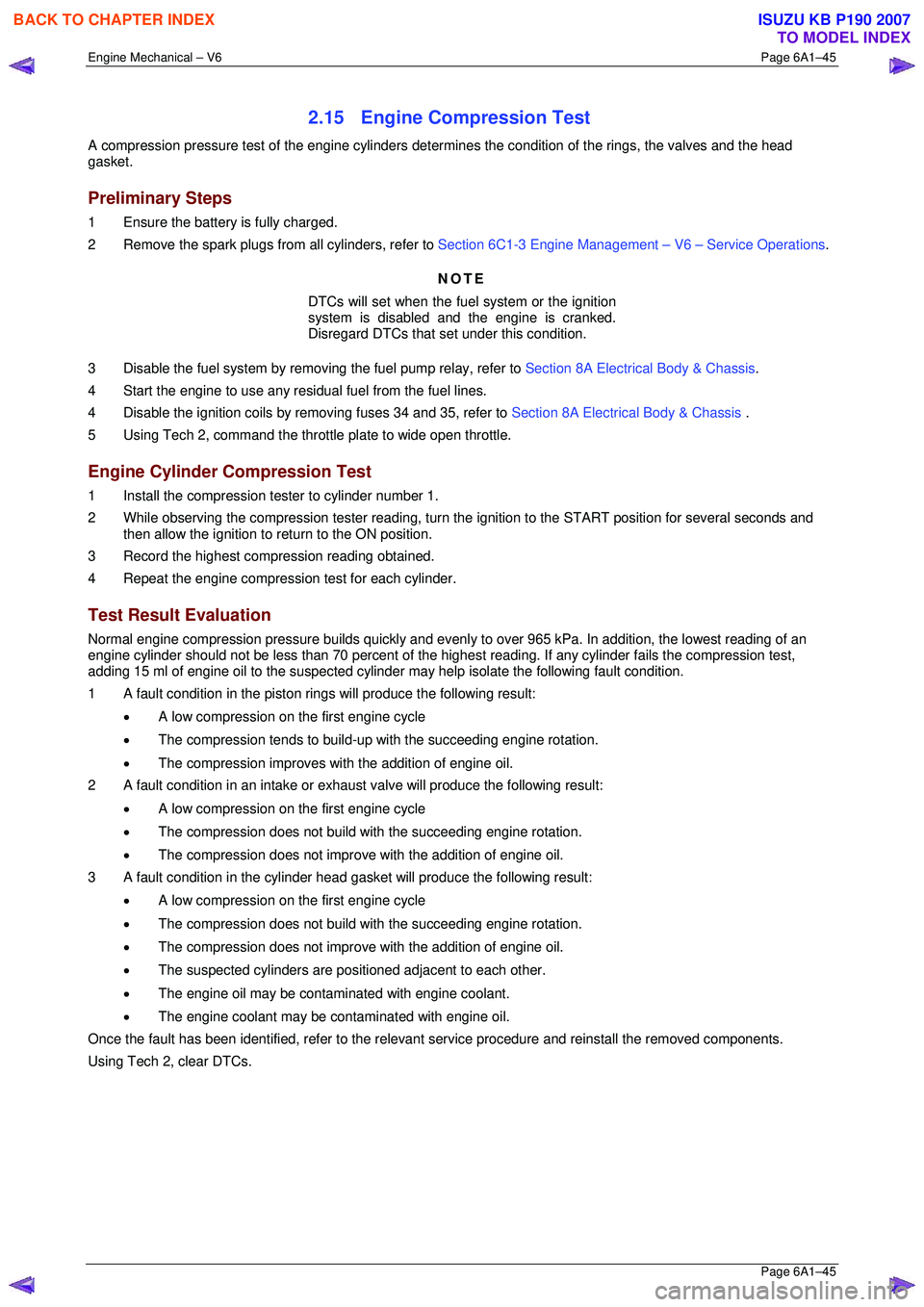
2.15 Engine Compression Test
A compression pressure test of the engine cylinders determines the condition of the rings, the valves and the head
gasket.
Preliminary Steps
1 Ensure the battery is fully charged.
2 Remove the spark plugs from all cylinders, refer to Section 6C1-3 Engine Management – V6 – Service Operations.
NOTE
DTCs will set when the fuel system or the ignition
system is disabled and the engine is cranked.
Disregard DTCs that set under this condition.
3 Disable the fuel system by removi ng the fuel pump relay, refer to Section 8A Electrical Body & Chassis .
4 Start the engine to use any resi dual fuel from the fuel lines.
4 Disable the ignition coils by removing fuses 34 and 35, refer to Section 8A Electrical Body & Chassis .
5 Using Tech 2, command the throttle plate to wide open throttle.
Engine Cylinder Compression Test
1 Install the compression tester to cylinder number 1.
2 While observing the compression tester reading, turn t he ignition to the START position for several seconds and
then allow the ignition to return to the ON position.
3 Record the highest compression reading obtained.
4 Repeat the engine compression test for each cylinder.
Test Result Evaluation
Normal engine compression pressure builds quickly and evenly to over 965 kPa. In addition, the lowest reading of an
engine cylinder should not be less than 70 per cent of the highest reading. If any cylinder fails the compression test,
adding 15 ml of engine oil to the suspected cylinder may help isolate the following fault condition.
1 A fault condition in the piston rings will produce the following result:
• A low compression on the first engine cycle
• The compression tends to build-up with the succeeding engine rotation.
• The compression improves with the addition of engine oil.
2 A fault condition in an intake or exhaus t valve will produce the following result:
• A low compression on the first engine cycle
• The compression does not build with the succeeding engine rotation.
• The compression does not improve with the addition of engine oil.
3 A fault condition in the cylinder head gasket will produce the following result:
• A low compression on the first engine cycle
• The compression does not build with the succeeding engine rotation.
• The compression does not improve with the addition of engine oil.
• The suspected cylinders are pos itioned adjacent to each other.
• The engine oil may be contaminated with engine coolant.
• The engine coolant may be cont aminated with engine oil.
Once the fault has been identified, refe r to the relevant service procedure and reinstall the removed components.
Using Tech 2, clear DTCs.
BACK TO CHAPTER INDEX
TO MODEL INDEX
ISUZU KB P190 2007
Page 2823 of 6020
Engine Mechanical – V6 Page 6A1–46
Page 6A1–46
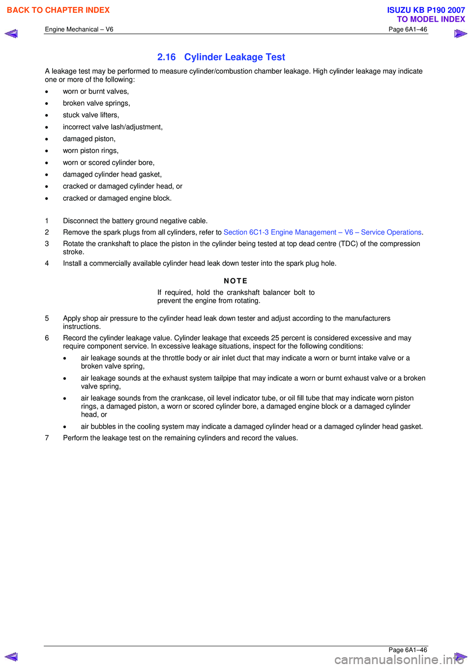
2.16 Cylinder Leakage Test
A leakage test may be performed to measure cylinder/combustion chamber leakage. High cylinder leakage may indicate
one or more of the following:
• worn or burnt valves,
• broken valve springs,
• stuck valve lifters,
• incorrect valve lash/adjustment,
• damaged piston,
• worn piston rings,
• worn or scored cylinder bore,
• damaged cylinder head gasket,
• cracked or damaged cylinder head, or
• cracked or damaged engine block.
1 Disconnect the battery ground negative cable.
2 Remove the spark plugs from all cylinders, refer to Section 6C1-3 Engine Management – V6 – Service Operations.
3 Rotate the crankshaft to place the piston in the cyli nder being tested at top dead centre (TDC) of the compression
stroke.
4 Install a commercially available cylinder head leak down tester into the spark plug hole.
NOTE
If required, hold the crankshaft balancer bolt to
prevent the engine from rotating.
5 Apply shop air pressure to the cylinder head leak dow n tester and adjust according to the manufacturers
instructions.
6 Record the cylinder leakage value. Cylinder leakage t hat exceeds 25 percent is considered excessive and may
require component service. In excessive leakage situations, inspect for the following conditions:
• air leakage sounds at the throttle body or air inlet duct that may indicate a worn or burnt intake valve or a
broken valve spring,
• air leakage sounds at the exhaust system tailpipe that may indicate a worn or burnt exhaust valve or a broken
valve spring,
• air leakage sounds from the crankcase, oil level indicator tube, or oil fill tube that may indicate worn piston
rings, a damaged piston, a worn or scored cylinder bore, a damaged engine block or a damaged cylinder
head, or
• air bubbles in the cooling system may indicate a damaged cylinder head or a damaged cylinder head gasket.
7 Perform the leakage test on the rema ining cylinders and record the values.
BACK TO CHAPTER INDEX
TO MODEL INDEX
ISUZU KB P190 2007
Page 2824 of 6020
Engine Mechanical – V6 Page 6A1–47
Page 6A1–47
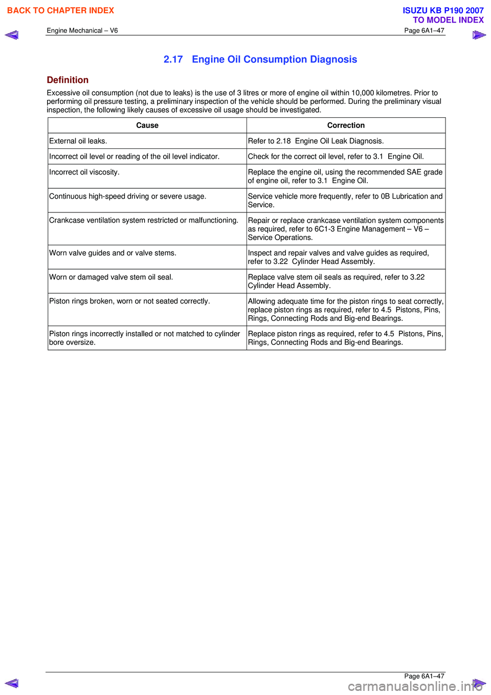
2.17 Engine Oil Consumption Diagnosis
Definition
Excessive oil consumption (not due to leaks) is the use of 3 litres or more of engine oil within 10,000 kilometres. Prior to
performing oil pressure testing, a prelim inary inspection of the vehicle should be performed. During the preliminary visual
inspection, the following likely causes of excessive oil usage should be investigated.
Cause Correction
External oil leaks. Refer to 2.18 Engine Oil Leak Diagnosis.
Incorrect oil level or reading of the oil level indicator. C heck for the correct oil level, refer to 3.1 Engine Oil.
Incorrect oil viscosity.
Replace the engine oil, using the recommended SAE grade
of engine oil, refer to 3.1 Engine Oil.
Continuous high-speed driving or severe usage. Service vehicle more frequently, refer to 0B Lubrication and
Service.
Crankcase ventilation system restricted or malfunctioning. Repair or replace crankcase ventilation system components
as required, refer to 6C1-3 Engine Management – V6 –
Service Operations.
Worn valve guides and or valve stems. Inspect and repair valves and valve guides as required,
refer to 3.22 Cylinder Head Assembly.
Worn or damaged valve stem oil seal. Replace valve stem oil seals as required, refer to 3.22
Cylinder Head Assembly.
Piston rings broken, worn or not seated correctly. Allowing adequate time for the piston rings to seat correctly,
replace piston rings as required, refer to 4.5 Pistons, Pins,
Rings, Connecting Rods and Big-end Bearings.
Piston rings incorrectly installed or not matched to cylinder
bore oversize. Replace piston rings as required, refer to 4.5 Pistons, Pins,
Rings, Connecting Rods and Big-end Bearings.
BACK TO CHAPTER INDEX
TO MODEL INDEX
ISUZU KB P190 2007
Page 2827 of 6020
Engine Mechanical – V6 Page 6A1–50
Page 6A1–50
2.19 Engine Oil Pressure Diagnosis
If the engine oil pressure is below the specified value, inspect the engine and components for the following:
• loose oil filter adaptor bolts,
• faulty oil filter adaptor seals,
• worn or faulty oil pump,
• loose oil pump bolts,
• loose, blocked or damaged oil pump suction pipe,
• faulty oil pump suction pipe seal,
• faulty oil pump pressure relief valve,
• faulty or incorrectly installed oil gallery plugs,
• excessive bearing clearance in one of the following:
• connecting rods big end/s,
• crankshaft main journal/s,
• camshaft/s,
• camshaft sprocket/s, and
• cracked, porous or restricted oil galleries, or broken lash adjuster/s.
BACK TO CHAPTER INDEX
TO MODEL INDEX
ISUZU KB P190 2007
Page 2845 of 6020
Engine Mechanical – V6 Page 6A1–68
Page 6A1–68
Pressure Check
1 Run the engine to bring it to normal operating temperature.
2 Park the vehicle on a level surface. A vehicle not level will affect the accuracy of the level reading.
3 Stop the engine and wait 5 to 10 minutes to a llow the oil to drain back into the oil pan.
4 Check the oil level and top up with the recommended engine o il as required, refer to Check, in this Section.
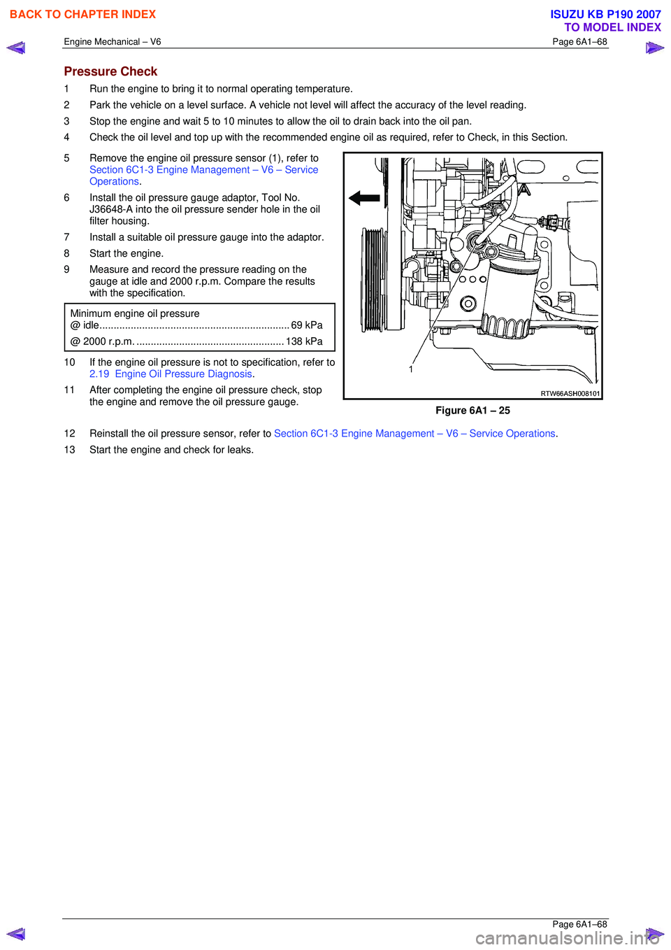
5 Remove the engine oil pressure sensor (1), refer to Section 6C1-3 Engine Management – V6 – Service
Operations .
6 Install the oil pressure gauge adaptor, Tool No. J36648-A into the oil pressure sender hole in the oil
filter housing.
7 Install a suitable oil pressure gauge into the adaptor.
8 Start the engine.
9 Measure and record the pressure reading on the gauge at idle and 2000 r.p.m. Compare the results
with the specification.
Minimum engine oil pressure
@ idle ................................................................... 69 kPa
@ 2000 r.p.m. .................................................... 138 kPa
10 If the engine oil pressure is not to specification, refer to
2.19 Engine Oil Pressure Diagnosis .
11 After completing the engine oil pressure check, stop the engine and remove the oil pressure gauge.
Figure 6A1 – 25
12 Reinstall the oil pressure sensor, refer to Section 6C1-3 Engine Management – V6 – Service Operations.
13 Start the engine and check for leaks.
BACK TO CHAPTER INDEX
TO MODEL INDEX
ISUZU KB P190 2007
Page 2847 of 6020
Engine Mechanical – V6 Page 6A1–70
Page 6A1–70
3.3 Oil Filter Adaptor
Remove
Disconnection of the battery affects
certain vehicle electronic systems, refer to
1.1 WARNING, CAUTION and NOTES before
disconnecting the battery.
1 Disconnect the battery negative terminal.
2 Disconnect the wiring harness connecto r from the oil pressure sender.
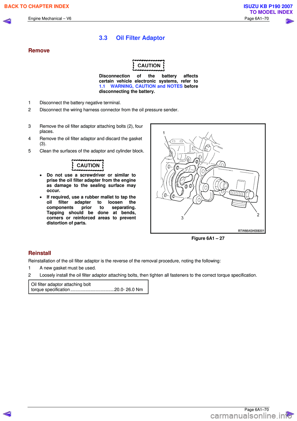
3 Remove the oil filter adaptor attaching bolts (2), four
places.
4 Remove the oil filter adaptor and discard the gasket (3).
5 Clean the surfaces of t he adaptor and cylinder block.
• Do not use a screwdriver or similar to
prise the oil filter adapter from the engine
as damage to the sealing surface may
occur.
• If required, use a rubber mallet to tap the
oil filter adapter to loosen the
components prior to separating.
Tapping should be done at bends,
corners or reinforced areas to prevent
distortion of parts.
Figure 6A1 – 27
Reinstall
Reinstallation of the oil filter adaptor is the reverse of the remo val procedure, noting the following:
1 A new gasket must be used.
2 Loosely install the oil filter adaptor attaching bolts, then tighten all fast eners to the correct torque specification.
Oil filter adaptor attaching bolt
torque specificatio n ...................................20.0- 26.0 Nm
BACK TO CHAPTER INDEX
TO MODEL INDEX
ISUZU KB P190 2007
Page 2992 of 6020
Engine Mechanical – V6 Page 6A1–215
Page 6A1–215
3.22 Stationary Hydraulic Lash Adjuster
Remove
1 Remove the rocker arms from the appropriate
cylinder head, refer to 3.20 Rocker Arm.
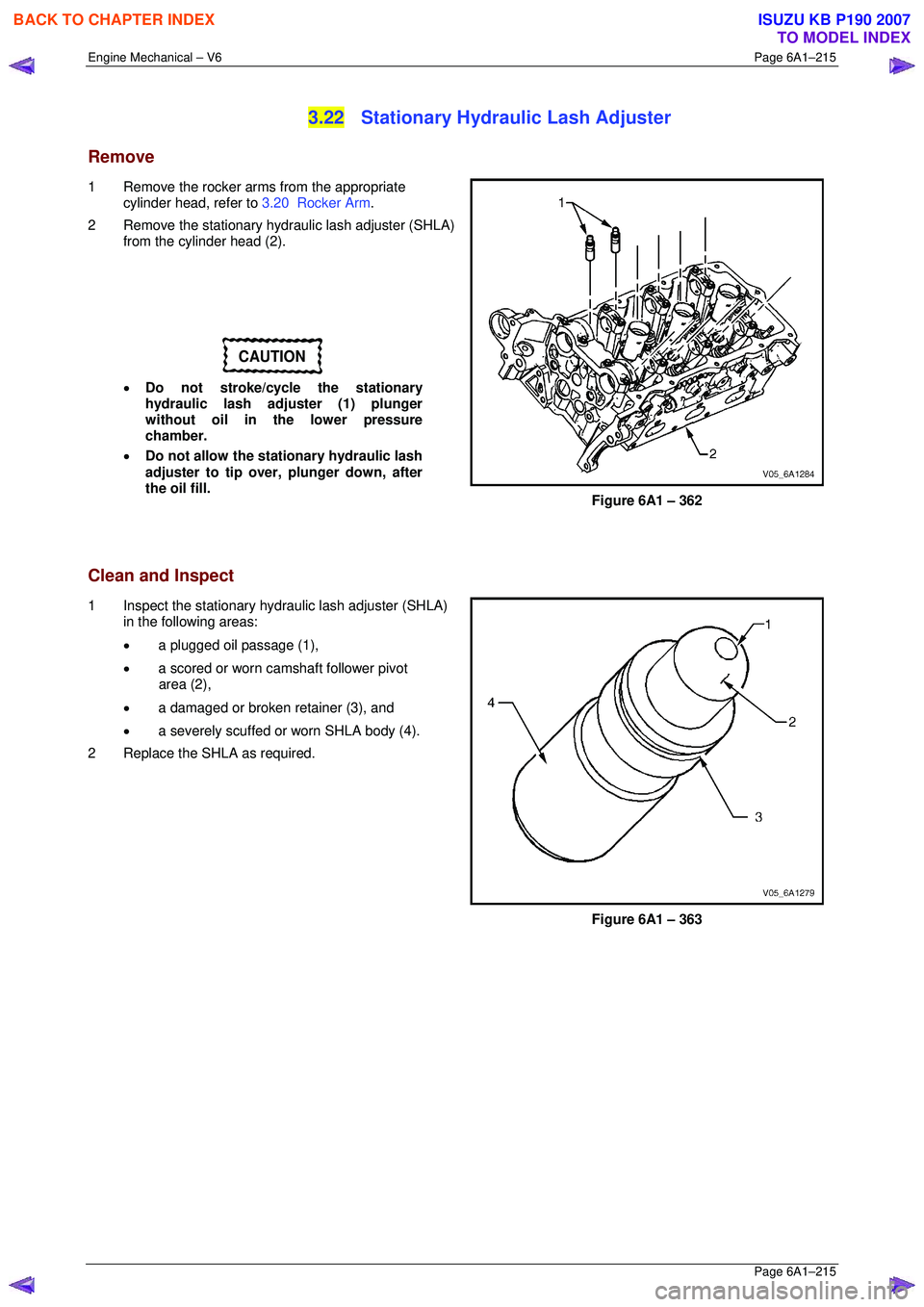
2 Remove the stationary hydraulic lash adjuster (SHLA) from the cylinder head (2).
CAUTION
• Do not stroke/cycle the stationary
hydraulic lash adjuster (1) plunger
without oil in the lower pressure
chamber.
• Do not allow the stationary hydraulic lash
adjuster to tip over, plunger down, after
the oil fill.
Figure 6A1 – 362
Clean and Inspect
1 Inspect the stationary hydraulic lash adjuster (SHLA) in the following areas:
• a plugged oil passage (1),
• a scored or worn camshaft follower pivot
area (2),
• a damaged or broken retainer (3), and
• a severely scuffed or worn SHLA body (4).
2 Replace the SHLA as required.
Figure 6A1 – 363
BACK TO CHAPTER INDEX
TO MODEL INDEX
ISUZU KB P190 2007