2007 ISUZU KB P190 fuel cap
[x] Cancel search: fuel capPage 981 of 6020

FUEL SYSTEM 6C – 17
FUEL FILLER CAP
RTW 46CSH000301
Legend
1. Seal Ring
General Description
A vacuum valve and pressure valve are built into the fuel filler
cap which adjusts the fuel pressure in the fuel tank to prevent
fuel tank damage.
Inspection
The fuel filler cap must be inspected for seal condition.
The fuel filler cap must be replaced if found defective
CAUTION: A replacement fuel filler cap must be the same
as the original. The fuel filler cap valve was designed
primarily for this application and must be replaced with
the same type or decreased engine performance may
occur.
BACK TO CHAPTER INDEX
TO MODEL INDEX
ISUZU KB P190 2007
Page 983 of 6020

FUEL SYSTEM 6C – 19
7. Power Steering Pump Bracket
6C-4 8. Throttle Position Sensor Harness Connector
(4JA1TC/4JH1TC only) Disconnect the harness connector from the throttle
position sensor.
9. Oil Level Gauge
10. Fuel Pipe 1) Disconnect the fuel hoses from the fuel filter or priming pump.
2) Disconnect the fuel hoses from the injection pump.
11. Fuel Filter Assembly (Except EURO III model)
6C-5
12. Fuel Filter Bracket (Except EURO III model)
13. Leak Off Hose
Disconnect the leak off hose at the injection pump.
14. Injection Pipe Clip
15. Injection Pipe
1) Loosen the injection pipe sleeve nuts at the delivery valve side and the injection nozzle side.
Note:
Do not apply excessive force to the injection pipes.
2) Loosen the injection pipe clip.
3) Remove the injection pipes.
Note:
Plug the delivery holder ports with the caps to prevent
the entry of foreign material.
16. Intake Manifold 1) Remove the EGR valve from the intake manifold and EGR pipe.
2) Loosen the intake rubber hoses clip.
3) Loosen the intake manifold bolts and nuts.
17. Injection Pump Cover (4JA1TC/4JH1TC only)
BACK TO CHAPTER INDEX
TO MODEL INDEX
ISUZU KB P190 2007
Page 1292 of 6020
6E-258 Engine Control System (4JH1)
Checks Action
Electromagnetic Interference (EMI)
and Electrical Noise Some electrical components/circuits are sensitive to EMI or other types of electrical
noise. Inspect for the following conditions:
• A misrouted harness that is too close to high voltage/high current devices such as
injection components, motors, generator etc. These components may induce
electrical noise on a circuit that could interfere with normal circuit operation.
• Electrical system interference caused by a malfunctioning relay, or the engine control
module (ECM) driven solenoid or switch. These conditions can cause a sharp
electrical surge. Normally, the problem will occur when the malfunctioning
component is operating.
• Improper installation of non-factory or aftermarket add on accessories such as lights,
2-way radios, amplifiers, electric motors, remote starters, alarm systems, cell
phones, etc. These accessories may lead to an emission related failure while in use,
but do not fail when the accessories are not in use.
• Test for an open diode across the A/C compressor clutch and for other open diodes.
Some relays may contain a clamping diode.
• Test the generator for a bad rectifier bridge that may be allowing AC noise into the
electrical system.
Incorrect ECM Programming • There are only a few situations where reprogramming a ECM is appropriate:
Important:
DO NOT reprogram the ECM with the SAME software/calibration files that are already
present in the ECM. This is not an effective repair for any type of driveability problem. - A ECM from another vehicle is installed.
- Revised software/calibration files have been released for this vehicle.
• Verify that the ECM contains the correct software/calibration. If incorrect
programming is found, reprogram the ECM with the most current
software/calibration.
Duplicating Failure Conditions • If none of the previous tests are successful, attempt to duplicate and/or capture the
failure conditions.
• An alternate method is to drive the vehicle with the DMM connected to a suspected
circuit. An abnormal reading on the DMM when the problem occurs, may help you
locate the problem.
scan tool Snapshot The scan tool can be set up to take a Snapshot of the parameters available via serial
data. The Snapshot function records live data over a period of time. The recorded data
can be played back and analyzed. The scan tool can also graph parameters singly or
in combinations of parameters for comparison. The Snapshot can be triggered
manually at the time the symptom is noticed, or set up in advance to trigger when a
DTC sets.
An abnormal value captured in the recorded data may point to a system or component
that needs to be investigated further.
Refer to the scan tool user instructions for more information on the Snapshot function.
Hard Start
Checks Action
DEFINITION:The engine cranks OK, but does not start for a long time. The engine does eventually run, or may start but
immediately dies.
Preliminary Checks •
Diagnostic System Check - Engine Controls.
• Ensure the driver is using the correct starting procedure.
• Inspect the engine control module (ECM) and fuel injection pump control unit (PCU)
grounds for being clean, tight, and in their proper locations.
• Inspect that the harness connectors are correctly connected.
• Inspect the fuel type and quality.
• Inspect the scan tool Data List in this section.
• Inspect the Service Bulletins for ECM software updates.
BACK TO CHAPTER INDEX
TO MODEL INDEX
ISUZU KB P190 2007
Page 1365 of 6020
ENGINE MECHANICAL (4JK1/4JJ1) 6A-5
EGR system
Based upon data, including water temperature, engine
speeds or engine loads, it is controlled via Engine
Control Module (ECM) to purify exhaust by recycling
part of it.
Its main components include an EGR valve, an EGR
cooler and various sensors.
Connecting rod cap bolt
The angular tightening method of the connecting rod
cap bolt further increases reliability and durability.
Fuel rail-type electronic control injection system
The fuel rail-type electronic control injection system is
composed of a fuel supply pump that sets the target
pressure of high-pressure fuel and supply it, a fuel rail
that measures such high-pressure fuel and a fuel
injector that turns it into a fine spray and injects it. Each
is controlled via ECM based upon various signals, while
injection timing or fuel injection quantity is controlled
under every possible driving condition.
Fuel injector
The fuel injector is a 6-hole nozzle that adjusts fuel
injection quantity or injection timing by opening o
r
closing an electromagnetic valve on the head of the fuel
injector.
ECM corrects the dispersion of fuel injection quantit
y
between fuel injector according to ID code data in
memory. At the replacement of fuel injector, ID code
data should be stored in ECM.
Fuel filter with sedimenter
It is a fuel filter with sedimenter that gets rid of water by
making use of the difference in specific gravity between
light oil and water, which comes with an indicator that
notifies you that it is filled with water.
Preheating system
The preheating system consists of the ECM, the glow
relay, glow plugs and the glow indicator lamp. The
preheating system is operated when the engine coolant
temperature is low, and makes the engine easy to start.
Lubrication system
It is an oil filter with full-flow bypass, which uses a
water-cool oil cooler and oil jet to cool the piston.
Functional inspection
Inspection/adjustment of valve clearance 1. Inspection of valve clearance
• Remove the fuel injector harness assembly.
• Remove the leak off hose.
• Remove the cylinder head cover.
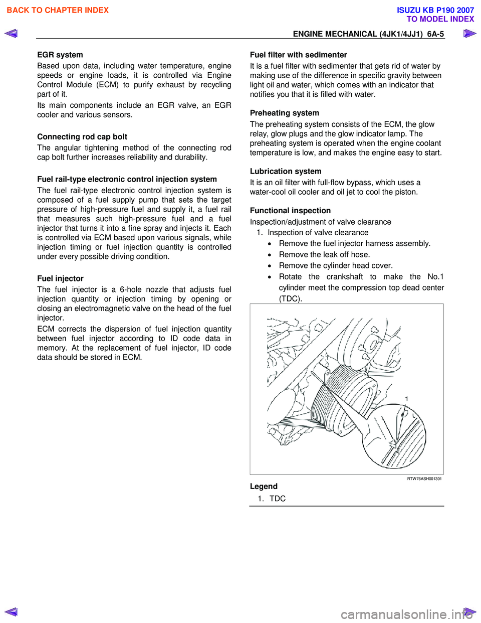
• Rotate the crankshaft to make the No.1
cylinder meet the compression top dead cente
r
(TDC).
RTW 76ASH001301
Legend
1. TDC
BACK TO CHAPTER INDEX
TO MODEL INDEX
ISUZU KB P190 2007
Page 1427 of 6020
ENGINE MECHANICAL (4JK1/4JJ1) 6A-67
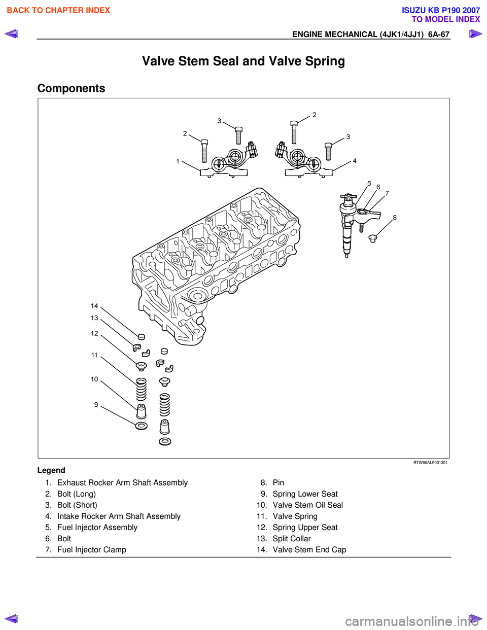
Valve Stem Seal and Valve Spring
Components
RTW 56ALF001301
Legend 1. Exhaust Rocker Arm Shaft Assembly
2. Bolt (Long)
3. Bolt (Short)
4. Intake Rocker Arm Shaft Assembly
5. Fuel Injector Assembly
6. Bolt
7. Fuel Injector Clamp 8. Pin
9. Spring Lower Seat
10. Valve Stem Oil Seal
11. Valve Spring
12. Spring Upper Seat
13. Split Collar
14. Valve Stem End Cap
BACK TO CHAPTER INDEX
TO MODEL INDEX
ISUZU KB P190 2007
Page 1487 of 6020
ENGINE MECHANICAL (4JK1/4JJ1) 6A-127
Removal
1. Demount the engine assembly.
Refer to "Engine Assembly".
2. Remove the cylinder head cover.
Refer to "Cylinder Head Cover".
3. Remove the camshaft.
Refer to "Camshaft Assembly".
4. Remove the cylinder head.
Refer to "Cylinder Head".
5. Remove the fuel supply pump and fuel rail.
Refer to "Fuel Supply Pump" and "Fuel Rail" in the fuel system section.
6. Remove the front cover.
Refer to "Front Cover".
7. Remove the crankshaft rear oil seal.
Refer to "Crankshaft Rear Oil Seal".
8. Remove the water pump.
Refer to "W ater Pump" in Cooling System Section.
9. Remove the timing gear train.
Refer to "Timing Gear Train".
10.Remove the oil pump.
Refer to "Oil Pump".
11. Remove the gear case assembly.
Refer to “Gear Case Assembly”.
12. Remove the crankshaft gear.
901R100008
13. Remove the crank case.
Refer to "Crank Case and Oil Pan".
14.Remove pistons and connecting rods.
Refer to "Piston and Connecting Rod".
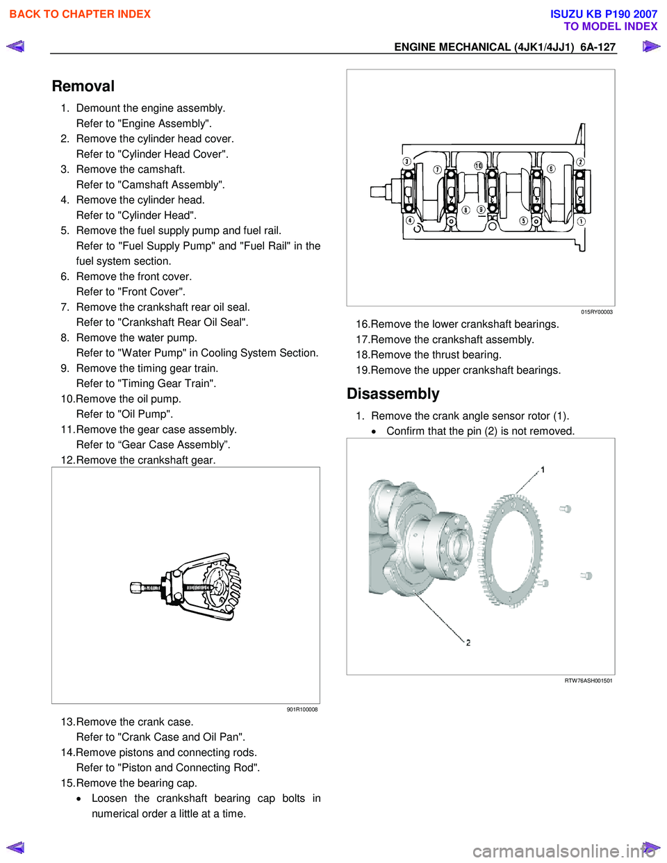
15. Remove the bearing cap. • Loosen the crankshaft bearing cap bolts in
numerical order a little at a time.
015RY00003
16.Remove the lower crankshaft bearings.
17.Remove the crankshaft assembly.
18.Remove the thrust bearing.
19.Remove the upper crankshaft bearings.
Disassembly
1. Remove the crank angle sensor rotor (1). • Confirm that the pin (2) is not removed.
RTW 76ASH001501
BACK TO CHAPTER INDEX
TO MODEL INDEX
ISUZU KB P190 2007
Page 1542 of 6020
FUEL SYSTEM (4JK1/4JJ1) 6C-1
SECTION 6C
FUEL SYSTEM
TABLE OF CONTENTS
Fuel System ....................................................... 6C-2 Service Precautions ........................................ 6C-2
Trouble Shooting ............................................. 6C-8
Fuel System Check ......................................... 6C-10
Fuel Filter Assembly ........................................... 6C-12 Components .................................................... 6C-12
Removal .......................................................... 6C-12
Installation ....................................................... 6C-12
Fuel Filter Cartridge............................................ 6C-13 Removal .......................................................... 6C-13
Installation ....................................................... 6C-13
Fuel Injector........................................................ 6C-14 Components .................................................... 6C-14
Removal .......................................................... 6C-15
Installation ....................................................... 6C-15
Torque Specifications...................................... 6C-18
Fuel Rail Pressure Sensor ................................. 6C-19 Removal .......................................................... 6C-19
Installation ....................................................... 6C-19
Fuel Pressure Limiter ......................................... 6C-20 Removal .......................................................... 6C-20
Installation ....................................................... 6C-20
Fuel Rail Assembly............................................. 6C-21 Components .................................................... 6C-21
Removal .......................................................... 6C-22
Disassembly .................................................... 6C-24
Reassembly..................................................... 6C-24
Installation ....................................................... 6C-24
Torque Specifications...................................... 6C-26
Fuel Supply Pump .............................................. 6C-27 Components .................................................... 6C-27
Removal .......................................................... 6C-28
Installation ....................................................... 6C-33
Torque Specifications...................................... 6C-38
Fuel Sedimenter Switch ..................................... 6C-39 Inspection ........................................................ 6C-39
Fuel Tank and Fuel Cooler ................................. 6C-40 Fuel Tank and Associated Parts ..................... 6C-40
Removal .......................................................... 6C-41
Installation ....................................................... 6C-41
Fuel Gauge Unit ................................................. 6C-42 Fuel Gauge Unit and Associated Parts ........... 6C-42
Removal .......................................................... 6C-43
Installation ....................................................... 6C-43
Special Tool .................................................... 6C-43
Fuel Tube/Quick-Connector Fittings .................. 6C-44 Precautions ..................................................... 6C-44
Cautions During W ork ..................................... 6C-44
Removal .......................................................... 6C-44
Reuse of Quick-Connector.............................. 6C-45
Assembling Advice .......................................... 6C-45
Filler Neck .......................................................... 6C-46 Removal .......................................................... 6C-46
Installation ....................................................... 6C-46
Fuel Filler Cap .................................................... 6C-47 General Description ........................................ 6C-47
Inspection ........................................................ 6C-47
BACK TO CHAPTER INDEX
TO MODEL INDEX
ISUZU KB P190 2007
Page 1544 of 6020
FUEL SYSTEM (4JK1/4JJ1) 6C-3
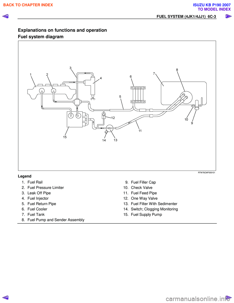
Explanations on functions and operation
Fuel system diagram
RTW 76CMF000101
Legend
1. Fuel Rail
2. Fuel Pressure Limiter
3. Leak Off Pipe
4. Fuel Injector
5. Fuel Return Pipe
6. Fuel Cooler
7. Fuel Tank
8. Fuel Pump and Sender Assembly
9. Fuel Filler Cap
10. Check Valve
11. Fuel Feed Pipe
12. One W ay Valve 13. Fuel Filter W ith Sedimenter
14. Switch; Clogging Monitoring
15. Fuel Supply Pump
BACK TO CHAPTER INDEX
TO MODEL INDEX
ISUZU KB P190 2007