2007 ISUZU KB P190 fuel cap
[x] Cancel search: fuel capPage 3278 of 6020
Engine Management – V6 – General Information Page 6C1-1–36
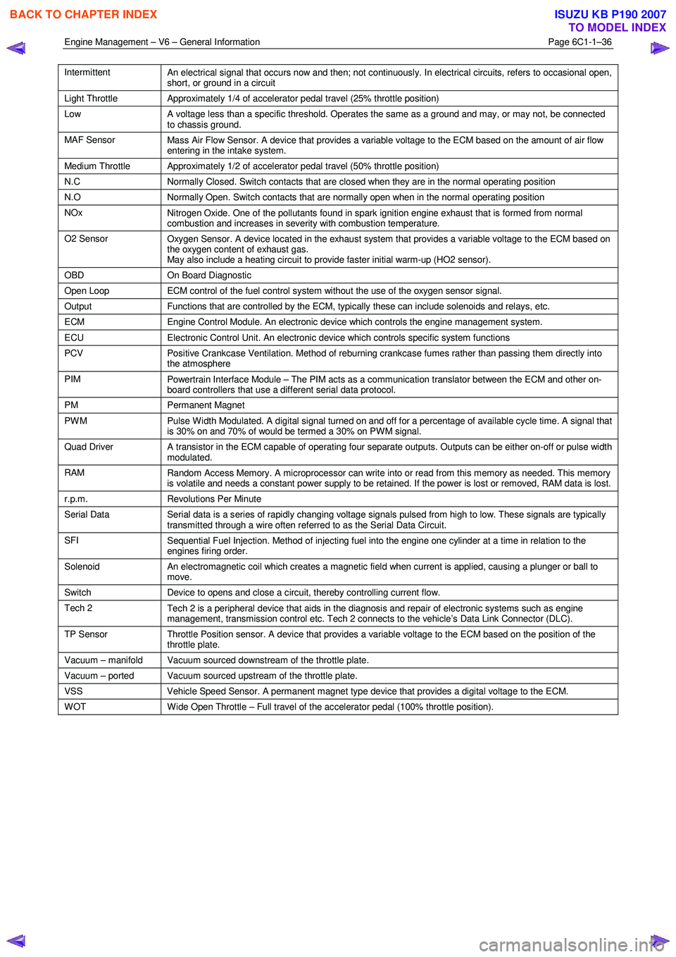
Intermittent
An electrical signal that occurs now and then; not continuously. In electrical circuits, refers to occasional open,
short, or ground in a circuit
Light Throttle Approximately 1/4 of accelerator pedal travel (25% throttle position)
Low
A voltage less than a specific threshold. Operates the same as a ground and may, or may not, be connected
to chassis ground.
MAF Sensor Mass Air Flow Sensor. A device that provides a variable voltage to the ECM based on the amount of air flow
entering in the intake system.
Medium Throttle Approximately 1/2 of accelerator pedal travel (50% throttle position)
N.C Normally Closed. Switch contacts that are closed when they are in the normal operating position
N.O Normally Open. Switch contacts that are normally open when in the normal operating position
NOx
Nitrogen Oxide. One of the pollutants found in spark ignition engine exhaust that is formed from normal
combustion and increases in severity with combustion temperature.
O2 Sensor Oxygen Sensor. A device located in the exhaust system that provides a variable voltage to the ECM based on
the oxygen content of exhaust gas.
May also include a heating circuit to provide faster initial warm-up (HO2 sensor).
OBD On Board Diagnostic
Open Loop ECM control of the fuel control system without the use of the oxygen sensor signal.
Output Functions that are controlled by the ECM, typically these can include solenoids and relays, etc.
ECM Engine Control Module. An electronic device which controls the engine management system.
ECU Electronic Control Unit. An electronic device which controls specific system functions
PCV
Positive Crankcase Ventilation. Method of reburning crankcase fumes rather than passing them directly into
the atmosphere
PIM Powertrain Interface Module – The PIM acts as a communication translator between the ECM and other on-
board controllers that use a different serial data protocol.
PM Permanent Magnet
PWM
Pulse Width Modulated. A digital signal turned on and off for a percentage of available cycle time. A signal that
is 30% on and 70% of would be termed a 30% on PWM signal.
Quad Driver A transistor in the ECM capable of operating four separate outputs. Outputs can be either on-off or pulse width
modulated.
RAM Random Access Memory. A microprocessor can write into or read from this memory as needed. This memory
is volatile and needs a constant power supply to be retained. If the power is lost or removed, RAM data is lost.
r.p.m. Revolutions Per Minute
Serial Data
Serial data is a series of rapidly changing voltage signals pulsed from high to low. These signals are typically
transmitted through a wire often referred to as the Serial Data Circuit.
SFI Sequential Fuel Injection. Method of injecting fuel into the engine one cylinder at a time in relation to the
engines firing order.
Solenoid An electromagnetic coil which creates a magnetic field when current is applied, causing a plunger or ball to
move.
Switch Device to opens and close a circuit, thereby controlling current flow.
Tech 2
Tech 2 is a peripheral device that aids in the diagnosis and repair of electronic systems such as engine
management, transmission control etc. Tech 2 connects to the vehicle’s Data Link Connector (DLC).
TP Sensor Throttle Position sensor. A device that provides a variable voltage to the ECM based on the position of the
throttle plate.
Vacuum – manifold Vacuum sourced downstream of the throttle plate.
Vacuum – ported Vacuum sourced upstream of the throttle plate.
VSS Vehicle Speed Sensor. A permanent magnet type device that provides a digital voltage to the ECM.
WOT Wide Open Throttle – Full travel of the accelerator pedal (100% throttle position).
BACK TO CHAPTER INDEX
TO MODEL INDEX
ISUZU KB P190 2007
Page 3399 of 6020
Engine Management – V6 – Diagnostics Page 6C1-2–121
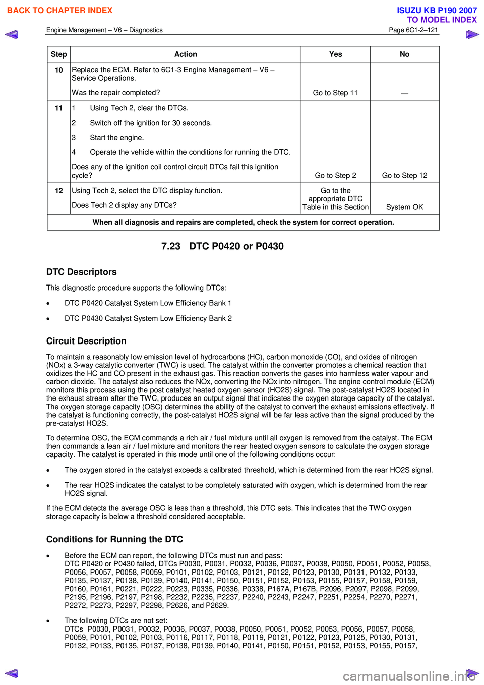
Step Action Yes No
10 Replace the ECM. Refer to 6C1-3 Engine Management – V6 –
Service Operations.
W as the repair completed? Go to Step 11 —
11 1 Using Tech 2, clear the DTCs.
2 Switch off the ignition for 30 seconds.
3 Start the engine.
4 Operate the vehicle within the conditions for running the DTC.
Does any of the ignition coil control circuit DTCs fail this ignition
cycle? Go to Step 2 Go to Step 12
12 Using Tech 2, select the DTC display function.
Does Tech 2 display any DTCs? Go to the
appropriate DTC
Table in this Section System OK
When all diagnosis and repairs are completed, check the system for correct operation.
7.23 DTC P0420 or P0430
DTC Descriptors
This diagnostic procedure supports the following DTCs:
• DTC P0420 Catalyst System Low Efficiency Bank 1
• DTC P0430 Catalyst System Low Efficiency Bank 2
Circuit Description
To maintain a reasonably low emission level of hydrocarbons (HC), carbon monoxide (CO), and oxides of nitrogen
(NOx) a 3-way catalytic converter (TW C) is used. The catalyst within the converter promotes a chemical reaction that
oxidizes the HC and CO present in the exhaust gas. This reaction converts the gases into harmless water vapour and
carbon dioxide. The catalyst also reduces the NOx, converting the NOx into nitrogen. The engine control module (ECM)
monitors this process using the post catalyst heated oxygen sensor (HO2S) signal. The post-catalyst HO2S located in
the exhaust stream after the TW C, produces an output signal that indicates the oxygen storage capacity of the catalyst.
The oxygen storage capacity (OSC) determines the ability of the catalyst to convert the exhaust emissions effectively. If
the catalyst is functioning correctly, the post-catalyst HO2S signal will be far less active than the signal produced by the
pre-catalyst HO2S.
To determine OSC, the ECM commands a rich air / fuel mixture until all oxygen is removed from the catalyst. The ECM
then commands a lean air / fuel mixture and monitors the rear heated oxygen sensors to calculate the oxygen storage
capacity. The catalyst is operated in this mode until one of the following conditions occur:
• The oxygen stored in the catalyst exceeds a calibrated threshold, which is determined from the rear HO2S signal.
• The rear HO2S indicates the catalyst to be completely saturated with oxygen, which is determined from the rear
HO2S signal.
If the ECM detects the average OSC is less than a threshold, this DTC sets. This indicates that the TW C oxygen
storage capacity is below a threshold considered acceptable.
Conditions for Running the DTC
• Before the ECM can report, the following DTCs must run and pass:
DTC P0420 or P0430 failed, DTCs P0030, P0031, P0032, P0036, P0037, P0038, P0050, P0051, P0052, P0053,
P0056, P0057, P0058, P0059, P0101, P0102, P0103, P0121, P0122, P0123, P0130, P0131, P0132, P0133,
P0135, P0137, P0138, P0139, P0140, P0141, P0150, P0151, P0152, P0153, P0155, P0157, P0158, P0159,
P0160, P0161, P0221, P0222, P0223, P0335, P0336, P0338, P167A, P167B, P2096, P2097, P2098, P2099,
P2195, P2196, P2197, P2198, P2232, P2235, P2237, P2240, P2243, P2247, P2251, P2254, P2270, P2271,
P2272, P2273, P2297, P2298, P2626, and P2629.
• The following DTCs are not set:
DTCs P0030, P0031, P0032, P0036, P0037, P0038, P0050, P0051, P0052, P0053, P0056, P0057, P0058,
P0059, P0101, P0102, P0103, P0116, P0117, P0118, P0119, P0121, P0122, P0123, P0125, P0130, P0131,
P0132, P0133, P0135, P0137, P0138, P0139, P0140, P0141, P0150, P0151, P0152, P0153, P0155, P0157,
BACK TO CHAPTER INDEX
TO MODEL INDEX
ISUZU KB P190 2007
Page 3463 of 6020
Engine Management – V6 – Diagnostics Page 6C1-2–185
Conditions for Setting the DTC
• The Total Fuel Trim Avg. is more than 23 percent.
• The condition exists for 4 seconds.
Action Taken When the DTC Sets
• The control module illuminates the malfunction indicator lamp (MIL) on the second consecutive ignition cycle that
the diagnostic runs and fails.
• The control module records the operating conditions at the time the diagnostic fails. The first time the diagnostic
fails, the control module stores this information in the Failure Records. If the diagnostic reports a failure on the
second consecutive ignition cycle, the control module records the operating conditions at the time of the failure.
The control module writes the operating conditions to the Freeze Frame and updates the Failure Records.
Conditions for Clearing the MIL/DTC
• The control module turns OFF the malfunction indicator lamp (MIL) after four consecutive ignition cycles that the
diagnostic runs and does not fail.
• A current DTC, Last Test Failed, clears when the diagnostic runs and passes.
• A history DTC clears after 40 consecutive warm-up cycles, if no failures are reported by this or any other emission
related diagnostic.
• Use Tech 2 to clear the MIL and the DTC.
Additional Information
• A fuel system delivery condition causes this DTC to set. Thoroughly inspect all items that cause a lean condition.
• Any un-metered air into the engine causes this DTC to set. Thoroughly inspect all areas of the engine for vacuum
leaks.
• For an intermittent fault condition, refer to 5.2 Intermittent Fault Conditions in this Section.
• To assist diagnosis, refer to 3 W iring Diagrams and Connector Charts in this Section, for the system wiring
diagram and connector charts.
Test Description
The numbers below refer to the step numbers on the diagnostic table.
2 This step determines if there is a current condition.
4 If DTC P2177 and P2179 are set at the same time, this indicates that both banks of the engine are operating lean. Inspect for items that would cause both banks of the engine to operate lean.
5 Disconnecting the mass air flow (MAF) sensor determines if the MAF sensor signal is skewed. If the Short Term FT parameter changes more than the specified value, there is a condition with the MAF sensor. A MAF sensor
condition can cause this DTC without setting a MAF DTC. If there is a MAF sensor condition, the MAF sensor
parameters will appear to be within range.
6 A vacuum leak causes DTC P2177 and P2179 to set at the same time. Inspect all areas of the engine for a vacuum leak. Also inspect the PCV valve for being the correct one for this application. Make sure that the engine
oil fill cap is in place and that it is tight. Verify that the engine oil dip stick is fully seated.
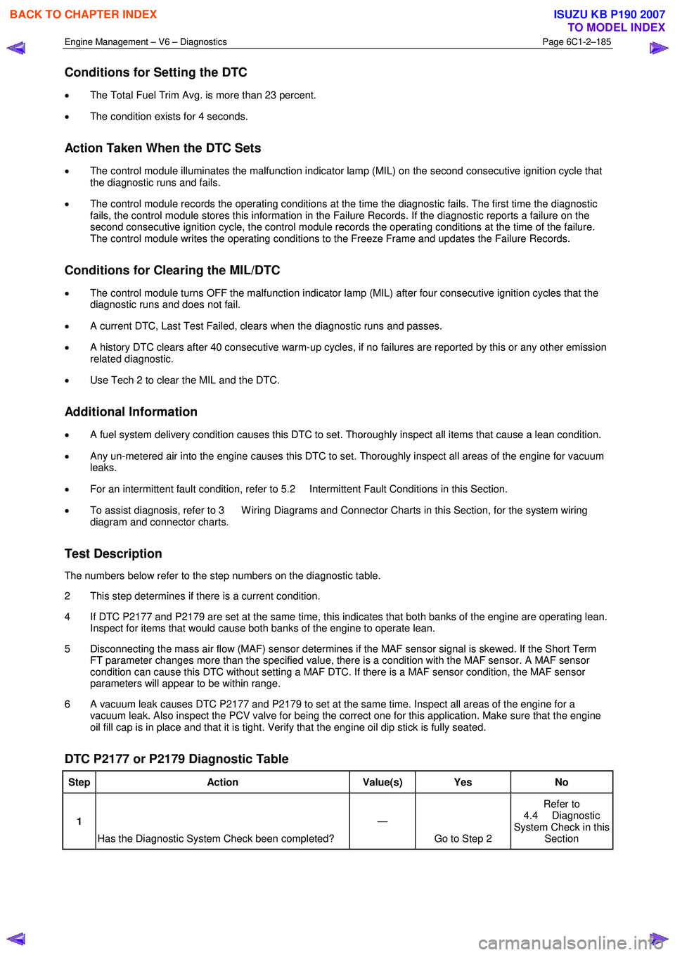
DTC P2177 or P2179 Diagnostic Table
Step Action Value(s) Yes No
1
Has the Diagnostic System Check been completed? —
Go to Step 2 Refer to
4.4 Diagnostic
System Check in this Section
BACK TO CHAPTER INDEX
TO MODEL INDEX
ISUZU KB P190 2007
Page 3470 of 6020
Engine Management – V6 – Diagnostics Page 6C1-2–192
Additional Information
• A fuel delivery condition causes this DTC to set. Thoroughly inspect all items that could cause a rich condition.
• For an intermittent fault condition, refer to 5.2 Intermittent Fault Conditions in this Section.
• Since fault condition in a wiring connector may trigger DTCs, always test the connectors related to this diagnostic
procedure for shorted terminals or poor wiring connection before replacing any component. Refer to 8A Electrical -
Body and Chassis for information on electrical fault diagnosis.
• To assist diagnosis, refer to 3 W iring Diagrams and Connector Charts in this Section, for the system wiring
diagram and connector charts.
Test Description
The numbers below refer to the step numbers on the diagnostic table.
2 This step determines if there is a current condition.
4 If DTC P2187 and P2189 are set at the same time, this indicates that both banks of the engine are operating lean. Inspect for items that would cause both banks of the engine to operate lean.
5 Disconnecting the mass air flow (MAF) sensor determines if the MAF sensor signal is skewed. If the Short Term FT parameter changes more than the specified value, there is a condition with the MAF sensor. A MAF sensor
condition can cause this DTC without setting a MAF DTC. If there is a MAF sensor condition, the MAF sensor
parameters will appear to be within range.
6 A vacuum leak causes DTC P2187 and P2189 to set at the same time. Inspect all areas of the engine for a vacuum leak. Also inspect the positive crankcase ventilation (PCV) valve for being the correct one for this
application. Make sure that the engine oil fill cap is in place and that it is tight. Verify that the engine oil dip stick is
fully seated.
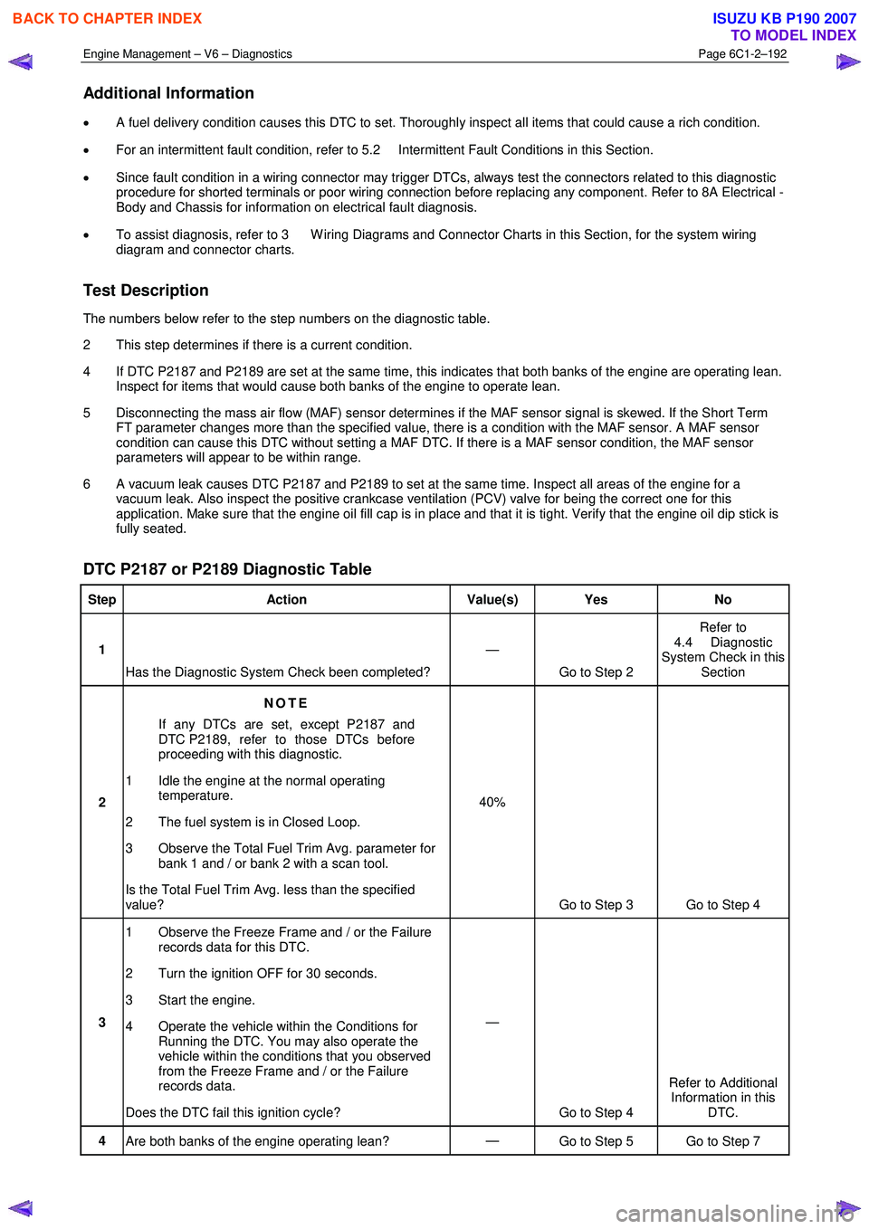
DTC P2187 or P2189 Diagnostic Table
Step Action Value(s) Yes No
1
Has the Diagnostic System Check been completed? —
Go to Step 2 Refer to
4.4 Diagnostic
System Check in this Section
2 NOTE
If any DTCs are set, except P2187 and
DTC P2189, refer to those DTCs before
proceeding with this diagnostic.
1 Idle the engine at the normal operating temperature.
2 The fuel system is in Closed Loop.
3 Observe the Total Fuel Trim Avg. parameter for bank 1 and / or bank 2 with a scan tool.
Is the Total Fuel Trim Avg. less than the specified
value? 40%
Go to Step 3 Go to Step 4
3 1 Observe the Freeze Frame and / or the Failure
records data for this DTC.
2 Turn the ignition OFF for 30 seconds.
3 Start the engine.
4 Operate the vehicle within the Conditions for Running the DTC. You may also operate the
vehicle within the conditions that you observed
from the Freeze Frame and / or the Failure
records data.
Does the DTC fail this ignition cycle? —
Go to Step 4 Refer to Additional
Information in this DTC.
4 Are both banks of the engine operating lean? —
Go to Step 5 Go to Step 7
BACK TO CHAPTER INDEX
TO MODEL INDEX
ISUZU KB P190 2007
Page 3502 of 6020
Engine Management – V6 – Diagnostics Page 6C1-2–224
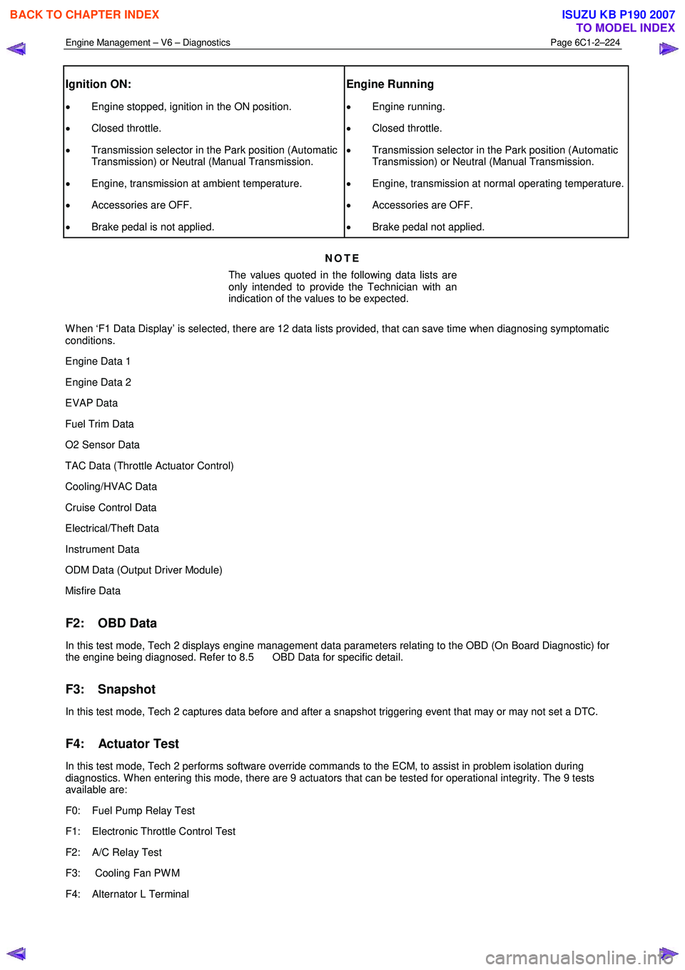
Ignition ON:
• Engine stopped, ignition in the ON position.
• Closed throttle.
• Transmission selector in the Park position (Automatic
Transmission) or Neutral (Manual Transmission.
• Engine, transmission at ambient temperature.
• Accessories are OFF.
• Brake pedal is not applied.
Engine Running
• Engine running.
• Closed throttle.
• Transmission selector in the Park position (Automatic
Transmission) or Neutral (Manual Transmission.
• Engine, transmission at normal operating temperature.
• Accessories are OFF.
• Brake pedal not applied.
NOTE
The values quoted in the following data lists are
only intended to provide the Technician with an
indication of the values to be expected.
W hen ‘F1 Data Display’ is selected, there are 12 data lists provided, that can save time when diagnosing symptomatic
conditions.
Engine Data 1
Engine Data 2
EVAP Data
Fuel Trim Data
O2 Sensor Data
TAC Data (Throttle Actuator Control)
Cooling/HVAC Data
Cruise Control Data
Electrical/Theft Data
Instrument Data
ODM Data (Output Driver Module)
Misfire Data
F2: OBD Data
In this test mode, Tech 2 displays engine management data parameters relating to the OBD (On Board Diagnostic) for
the engine being diagnosed. Refer to 8.5 OBD Data for specific detail.
F3: Snapshot
In this test mode, Tech 2 captures data before and after a snapshot triggering event that may or may not set a DTC.
F4: Actuator Test
In this test mode, Tech 2 performs software override commands to the ECM, to assist in problem isolation during
diagnostics. W hen entering this mode, there are 9 actuators that can be tested for operational integrity. The 9 tests
available are:
F0: Fuel Pump Relay Test
F1: Electronic Throttle Control Test
F2: A/C Relay Test
F3: Cooling Fan PW M
F4: Alternator L Terminal
BACK TO CHAPTER INDEX
TO MODEL INDEX
ISUZU KB P190 2007
Page 3571 of 6020
Engine Management – V6 – Service Operations Page 6C1-3–47
2.21 Schrader Valve – Fuel Pressure Gauge
Connection Point
If the Schrader valve is to be removed but not
replaced immediately, it is advisable to
disconnect the battery to avoid possible fuel
discharge if an accidental attempt is made to
start the engine.
Disconnection of the battery affects vehicle
electronic systems. Refer to 6D1-3 Battery –
V6 before disconnecting the battery.
Remove
1 Depressurise the fuel system, refer to 6C Fuel System - V6.
2 Turn the ignition off.
A small amount of fuel may be released when
servicing the fuel pressure test point. To
reduce the chance of personal injury, cover
the fuel pressure test point with a shop towel
to absorb any fuel spillage when the Schrader
valve sealing cap and Schrader valve are
removed. After the procedure, place the towel
in an approved container for disposal.
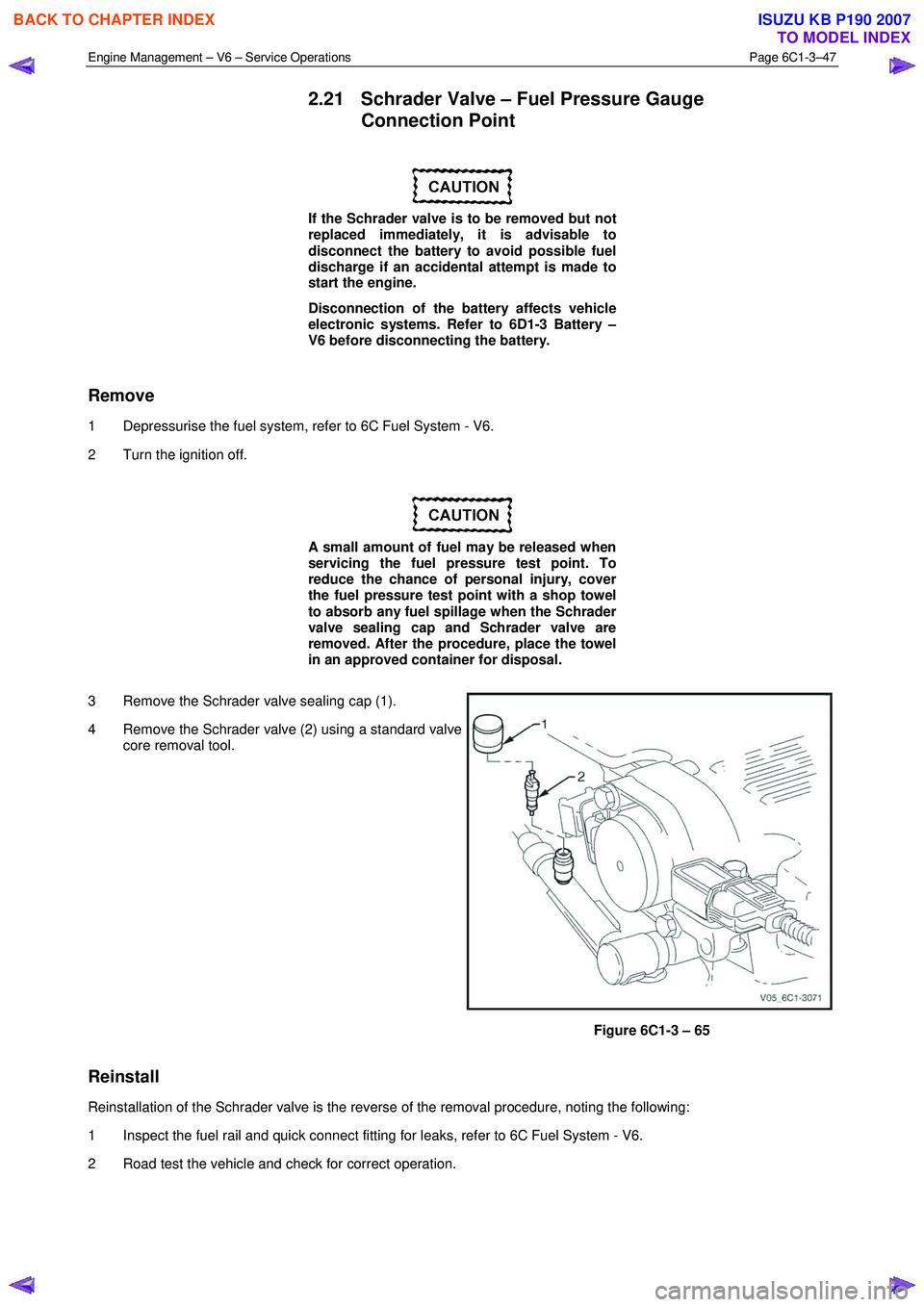
3 Remove the Schrader valve sealing cap (1).
4 Remove the Schrader valve (2) using a standard valve core removal tool.
Figure 6C1-3 – 65
Reinstall
Reinstallation of the Schrader valve is the reverse of the removal procedure, noting the following:
1 Inspect the fuel rail and quick connect fitting for leaks, refer to 6C Fuel System - V6.
2 Road test the vehicle and check for correct operation.
BACK TO CHAPTER INDEX
TO MODEL INDEX
ISUZU KB P190 2007
Page 3647 of 6020
Battery Page 6D1-3–7
3 Diagnosis
3.1 Diagnostic Procedures
Introduction
This test is used to aid in diagnosing faults with the vehicle where the battery seems to be at fault.
W ith the increased use of electronic sensors and computer control, the battery is much more than just a component used
to start a car. Low battery voltage can:
• affect the operation of the vehicle control modules and cause driveability problems, and
• cause the control modules to set diagnostic trouble codes (DTCs).
For example if a control module senses low battery voltage, it may increase fuel injector timing to increase engine rpm to
increase the generator output.
Therefore consider the state of charge of the battery any time a customer complains of a driveability related problem.
Test Description
The following numbers refer to the step numbers in the diagnostic table:
1 Checks the operator understands the safety precautions for working with batteries.
2 Checks if the vehicle is fitted with a battery of the correct specification.
3 Checks if the battery appears serviceable by performing the battery inspection procedure.
4 Checks if the battery loses charge over an extended period. If so the likely problem is excess current draw while the vehicles ignition is in the off position.
5 Checks the state of charge of the battery.
6 Checks if the battery is capable of delivering the required load by performing the load test procedure.
Diagnostic Table Notes
1 For all wiring harness fault diagnosis, refer to 8A Electrical Body & Chassis.
2 For wiring harness repairs, refer to 8A Electrical Body & Chassis.
3 Refer to 6D1 – 3 Battery – V6.
Diagnostic Table
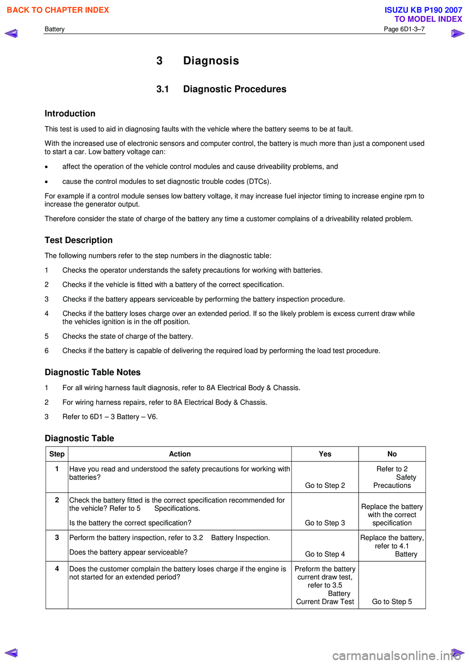
Step Action Yes No
1
Have you read and understood the safety precautions for working with
batteries? Go to Step 2 Refer to 2
Safety Precautions
2 Check the battery fitted is the correct specification recommended for
the vehicle? Refer to 5 Specifications.
Is the battery the correct specification? Go to Step 3 Replace the battery
with the correct
specification
3 Perform the battery inspection, refer to 3.2 Battery Inspection.
Does the battery appear serviceable? Go to Step 4 Replace the battery,
refer to 4.1
Battery
4 Does the customer complain the battery loses charge if the engine is
not started for an extended period? Preform the battery
current draw test, refer to 3.5
Battery
Current Draw Test Go to Step 5
BACK TO CHAPTER INDEX
TO MODEL INDEX
ISUZU KB P190 2007
Page 3656 of 6020
Battery Page 6D1-3–16
NOTE
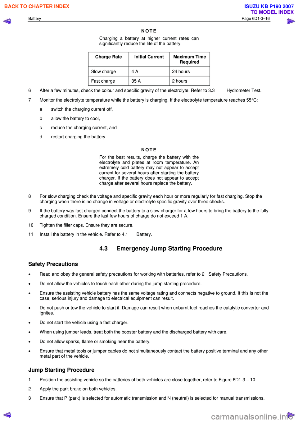
Charging a battery at higher current rates can
significantly reduce the life of the battery.
Charge Rate Initial Current Maximum Time Required
Slow charge 4 A 24 hours
Fast charge 35 A 2 hours
6 After a few minutes, check the colour and specific gravity of the electrolyte. Refer to 3.3 Hydrometer Test.
7 Monitor the electrolyte temperature while the battery is charging. If the electrolyte temperature reaches 55 °C:
a switch the charging current off,
b allow the battery to cool,
c reduce the charging current, and
d restart charging the battery.
NOTE
For the best results, charge the battery with the
electrolyte and plates at room temperature. An
extremely cold battery may not appear to accept
current for several hours after starting the battery
charger. If the battery does not appear to accept
charge after several hours replace the battery.
8 For slow charging check the voltage and specific gravity each hour or more regularly for fast charging. Stop the charging when there is no change in voltage or electrolyte specific gravity over three checks.
9 If the battery was fast charged connect the battery to a slow-charger for a few hours to bring the battery to the fully charged condition. Ensure the last few hours of charge do not exceed 1 A.
10 Tighten the filler caps. Ensure they are secure.
11 Install the battery in the vehicle. Refer to 4.1 Battery.
4.3 Emergency Jump Starting Procedure
Safety Precautions
• Read and obey the general safety precautions for working with batteries, refer to 2 Safety Precautions.
• Do not allow the vehicles to touch each other during the jump starting procedure.
• Ensure the assisting vehicle battery has the same voltage rating and connects negative to ground. If this is not the
case, serious injury and damage to electrical equipment can result.
• Do not push or tow the vehicle to start it. Damage can result when unburnt fuel reaches the catalytic converter and
ignites.
• Do not start the vehicle using a fast charger.
• W hen using jumper leads, treat both the booster battery and the discharged battery with care.
• Do not allow sparks, flame or smoking near the battery.
• Ensure that metal tools or jumper cables do not simultaneously contact the battery positive terminal and any other
metal part of the vehicle.
Jump Starting Procedure
1 Position the assisting vehicle so the batteries of both vehicles are close together, refer to Figure 6D1-3 – 10.
2 Apply the park brake on both vehicles.
3 Ensure that P (park) is selected for automatic transmission and N (neutral) is selected for manual transmissions.
BACK TO CHAPTER INDEX
TO MODEL INDEX
ISUZU KB P190 2007