2007 ISUZU KB P190 fuel cap
[x] Cancel search: fuel capPage 2788 of 6020
Engine Mechanical – V6 Page 6A1–11
Page 6A1–11
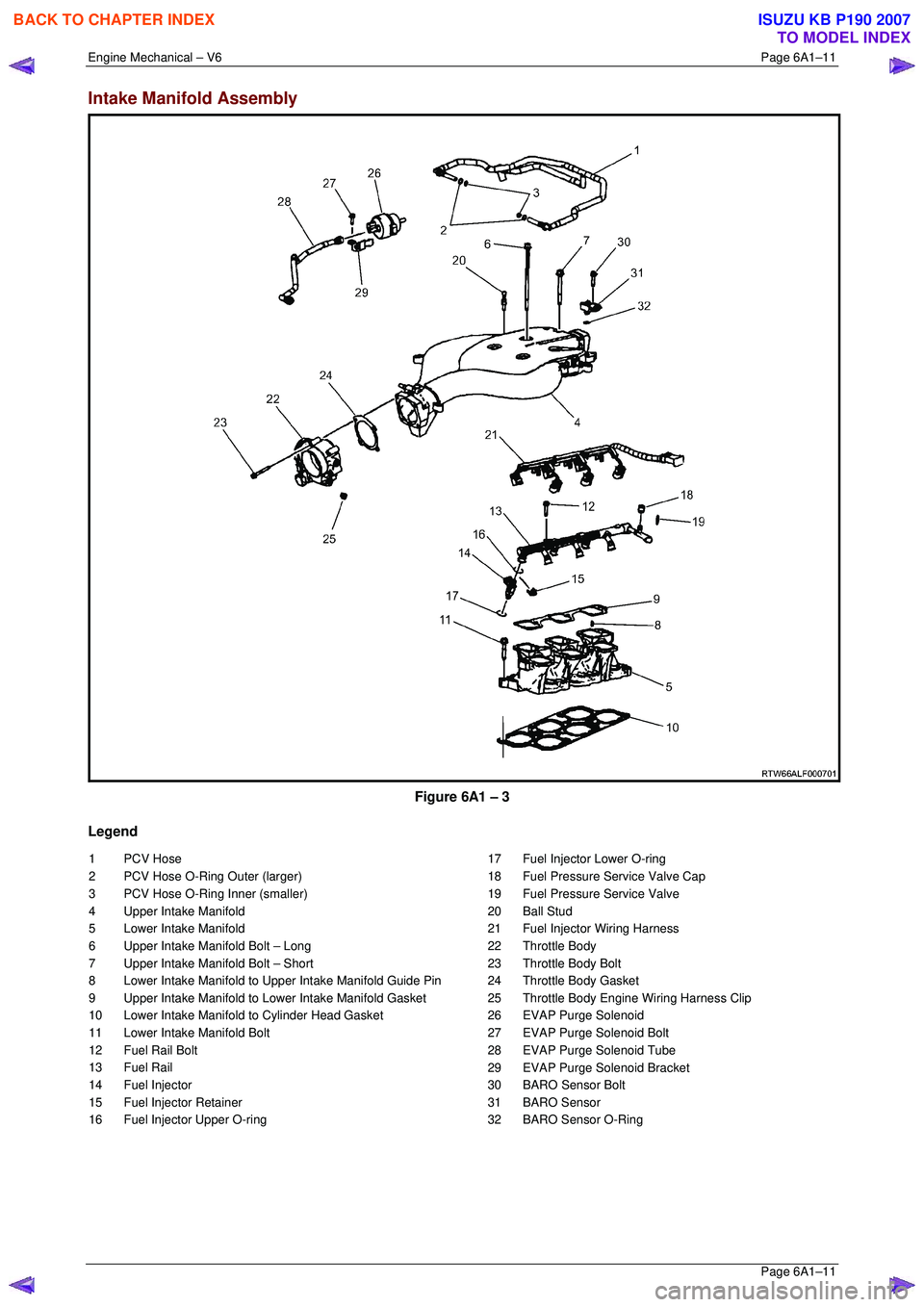
Intake Manifold Assembly
Figure 6A1 – 3
Legend
1 PCV Hose
2 PCV Hose O-Ring Outer (larger)
3 PCV Hose O-Ring Inner (smaller)
4 Upper Intake Manifold
5 Lower Intake Manifold
6 Upper Intake Manifold Bolt – Long
7 Upper Intake Manifold Bolt – Short
8 Lower Intake Manifold to Upper Intake Manifold Guide Pin
9 Upper Intake Manifold to Lower Intake Manifold Gasket
10 Lower Intake Manifold to Cylinder Head Gasket
11 Lower Intake Manifold Bolt
12 Fuel Rail Bolt
13 Fuel Rail
14 Fuel Injector
15 Fuel Injector Retainer
16 Fuel Injector Upper O-ring 17 Fuel Injector Lower O-ring
18 Fuel Pressure Service Valve Cap
19 Fuel Pressure Service Valve
20 Ball Stud
21 Fuel Injector Wiring Harness
22 Throttle Body
23 Throttle Body Bolt
24 Throttle Body Gasket
25 Throttle Body Engine Wiring Harness Clip
26 EVAP Purge Solenoid
27 EVAP Purge Solenoid Bolt
28 EVAP Purge Solenoid Tube
29 EVAP Purge Solenoid Bracket
30 BARO Sensor Bolt
31 BARO Sensor
32 BARO Sensor O-Ring
BACK TO CHAPTER INDEX
TO MODEL INDEX
ISUZU KB P190 2007
Page 2819 of 6020
Engine Mechanical – V6 Page 6A1–42
Page 6A1–42
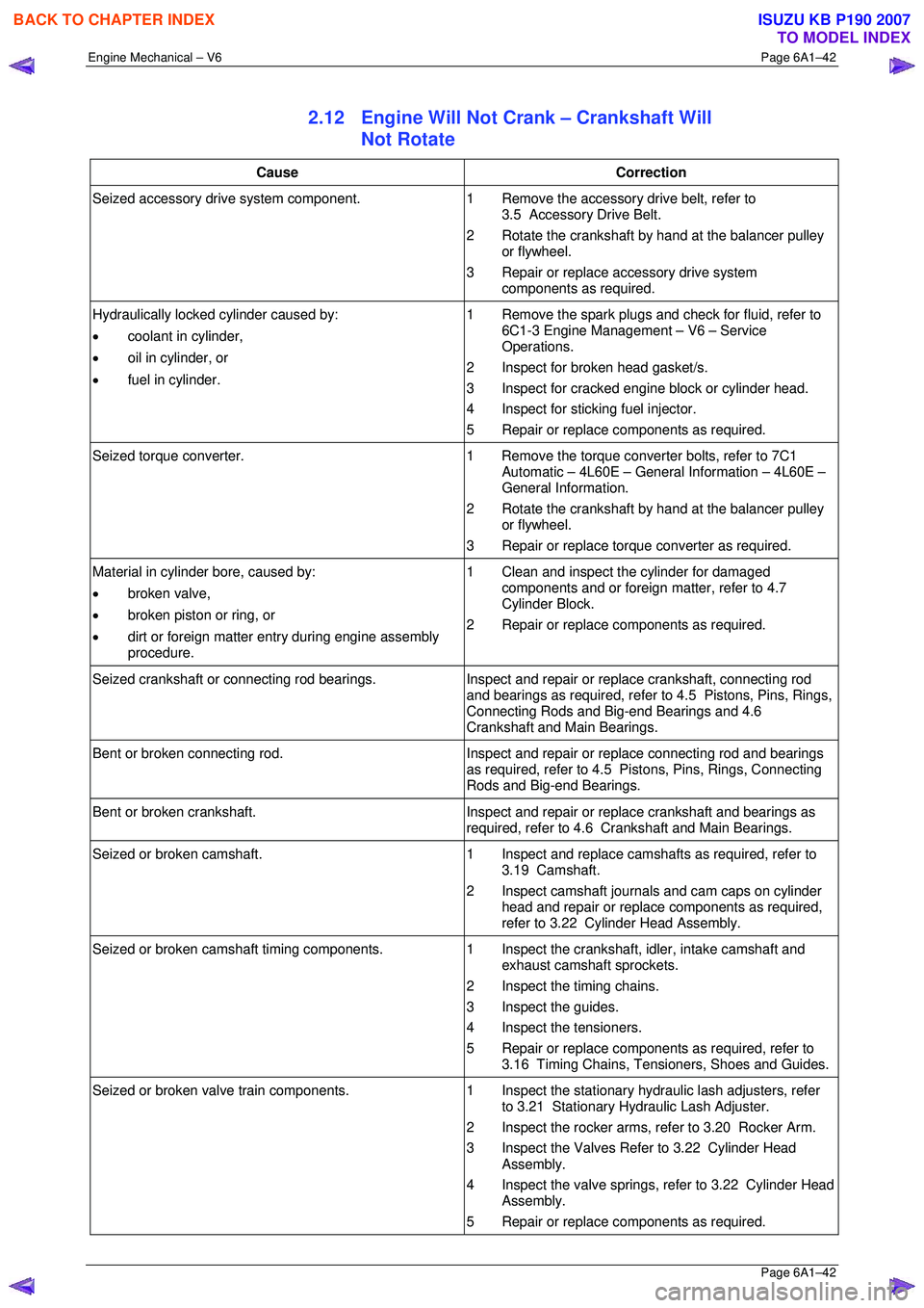
2.12 Engine Will Not Crank – Crankshaft Will
Not Rotate
Cause Correction
Seized accessory drive system component. 1 Remove the accessory drive belt, refer to
3.5 Accessory Drive Belt.
2 Rotate the crankshaft by hand at the balancer pulley or flywheel.
3 Repair or replace accessory drive system components as required.
Hydraulically locked cylinder caused by:
• coolant in cylinder,
• oil in cylinder, or
• fuel in cylinder. 1 Remove the spark plugs and check for fluid, refer to
6C1-3 Engine Management – V6 – Service
Operations.
2 Inspect for broken head gasket/s.
3 Inspect for cracked engine block or cylinder head.
4 Inspect for sticking fuel injector.
5 Repair or replace components as required.
Seized torque converter. 1 Remove the torque converter bolts, refer to 7C1
Automatic – 4L60E – General Information – 4L60E –
General Information.
2 Rotate the crankshaft by hand at the balancer pulley or flywheel.
3 Repair or replace torque converter as required.
Material in cylinder bore, caused by:
• broken valve,
• broken piston or ring, or
• dirt or foreign matter entry during engine assembly
procedure. 1 Clean and inspect the cylinder for damaged
components and or foreign matter, refer to 4.7
Cylinder Block.
2 Repair or replace components as required.
Seized crankshaft or connecting rod bearings. Inspect and repair or replace crankshaft, connecting rod
and bearings as required, refer to 4.5 Pistons, Pins, Rings,
Connecting Rods and Big-end Bearings and 4.6
Crankshaft and Main Bearings.
Bent or broken connecting rod. Inspect and repair or replace connecting rod and bearings
as required, refer to 4.5 Pistons, Pins, Rings, Connecting
Rods and Big-end Bearings.
Bent or broken crankshaft. Inspect and repair or replace crankshaft and bearings as
required, refer to 4.6 Crankshaft and Main Bearings.
Seized or broken camshaft. 1 Inspect and replace camshafts as required, refer to
3.19 Camshaft.
2 Inspect camshaft journals and cam caps on cylinder head and repair or replace components as required,
refer to 3.22 Cylinder Head Assembly.
Seized or broken camshaft timing components. 1 Inspect the crankshaft, idler, intake camshaft and
exhaust camshaft sprockets.
2 Inspect the timing chains.
3 Inspect the guides.
4 Inspect the tensioners.
5 Repair or replace components as required, refer to 3.16 Timing Chains, Tensioners, Shoes and Guides.
Seized or broken valve train components. 1 Inspect the stationary hydraulic lash adjusters, refer
to 3.21 Stationary Hydraulic Lash Adjuster.
2 Inspect the rocker arms, re fer to 3.20 Rocker Arm.
3 Inspect the Valves Refer to 3.22 Cylinder Head Assembly.
4 Inspect the valve springs, refer to 3.22 Cylinder Head Assembly.
5 Repair or replace components as required.
BACK TO CHAPTER INDEX
TO MODEL INDEX
ISUZU KB P190 2007
Page 3128 of 6020
Engine Mechanical – V6 Page 6A1–351
Page 6A1–351
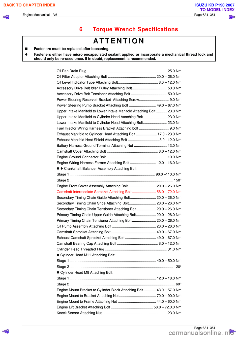
6 Torque Wrench Specifications
ATTENTION
�„ Fasteners must be replaced after loosening.
Fasteners either have micro encapsulated sealant a pplied or incorporate a mechanical thread lock and
should only be re-used once. If in doubt, replacement is recommended.
Oil Pan Drain Plug ................................................................................ 25.0 Nm
Oil Filter Adaptor Attach ing Bolt................................................ 20.0 – 26.0 Nm
Oil Level Indicator Tube Atta ching Bolt........................................ 8.0 – 12.0 Nm
Accessory Drive Belt Idler Pu lley Attaching Bolt................................... 50.0 Nm
Accessory Drive Belt Tensio ner Attaching Bolt .................................... 50.0 Nm
Power Steering Reserv oir Bracket Attaching Screw.............................. 9.0 Nm
Power Steering Pump Bracket A ttaching Bolt ........................... 49. 0 – 67.0 Nm
Upper Intake Manifold to Lower Intake Manifold Attaching Bolt ........... 23.0 Nm
Upper Intake Manifold to Cylinder Head Attaching Bolt........................ 23.0 Nm
Lower Intake Manifold to Cylind er Head Attaching Bolt........................ 23.0 Nm
Fuel Injector Wiring Harness Br acket Attaching bolt .............................. 9. 0 Nm
Exhaust Manifold to Cylinder He ad Attaching Bolt..................... 17.0 - 23.0 Nm
Exhaust Manifold Heat Shield Attaching Bolt ............................... 8.0 - 12.0 Nm
Battery Harness Ground Terminal Attaching Nut ................................. 13. 0 Nm
Camshaft Cover Attachi ng Bolt................................................... 8.0 – 12.0 Nm
Engine Ground Connec tor Bolt............................................................. 10.0 Nm
Engine Wiring Harness Former A ttaching Bolt .......................... 12.0 – 16.0 Nm
�„ Crankshaft Balancer A ssembly Attaching Bolt:
Stage 1 ..................................................................................... 90.0 –110.0 Nm
Stage 2 ....................................................................................................... 150 °
Engine Front Cover Assembly A ttaching Bolt ............................ 20. 0 – 26.0 Nm
Camshaft Intermediate Sprocket Attaching Bolt ........................ 58. 0 – 72.0 Nm
Secondary Timing Chai n Guide Attaching Bolt.......................... 20.0 – 26.0 Nm
Secondary Timing Chai n Shoe Attaching Bolt ........................... 20.0 – 26.0 Nm
Secondary Timing Chain Tensioner Attachi ng Bolt ................... 20.0 – 26.0 Nm
Primary Timing Chain Upper Gui de Attaching Bolt.................... 20.0 – 26.0 Nm
Primary Timing Chain Tensioner Attaching Bolt........................ 20. 0 – 26.0 Nm
Oil Pump Assembly Attach ing Bolt............................................ 20.0 – 26.0 Nm
Camshaft Sprocket Attachi ng Bolt............................................. 49.0 – 67.0 Nm
Exhaust Camshaft Sprocket Atta ching Bolt............................... 49.0 – 67.0 Nm
Camshaft Bearing Cap Attach ing Bolt......................................... 8.0 – 12.0 Nm
Cylinder Head Thr eaded Plug.............................................................. 31.0 Nm
�„ Cylinder Head M11 Attaching Bolt:
Stage 1 ...................................................................................... 40.0 – 50.0 Nm
Stage 2 ....................................................................................................... 120 °
�„ Cylinder Head M8 Attaching Bolt:
Stage 1 ...................................................................................... 12.0 – 18.0 Nm
Stage 2 ......................................................................................................... 60 °
Engine Mount Bracket to Cylinder Bl ock Attaching Bolt............ 43.0 – 57.0 Nm
Engine Mount to Bracket Atta ching Nut..................................... 70.0 – 90.0 Nm
Engine Mount to Frame Atta ching Nut...................................... 44.0 – 60.0 Nm
Engine Lift Bracket Attachi ng Bolt.......................................... 58.0 – 72.0.0 Nm
Knock Sensor Attach ing Nut................................................................. 23.0 Nm
BACK TO CHAPTER INDEX
TO MODEL INDEX
ISUZU KB P190 2007
Page 3204 of 6020
Fuel System – V6 Page 6C – 2
4.6 Evaporative Emission Control Canister............................................................................................................. 27
Remove ................................................................................................................................................................. 27
Service Check .................................................................................................................. .................................... 28
Reinstall ................................................................................................................................................................ 29
4.7 Fuel Tank Siphon Procedure ..................................................................................................... ......................... 30
4.8 Fuel Filler Cap ...................................................................................................................................................... 32
Remove ................................................................................................................................................................. 32
Inspection ......................................................................................................................................................... 32
Reinstall ................................................................................................................................................................ 32
4.9 Fuel Lines ..................................................................................................................... ........................................ 33
Remove ................................................................................................................................................................. 33
Fuel Tank Lines ................................................................................................................ .................................... 34
Reinstall ................................................................................................................................................................ 34
Fuel Line Routing.............................................................................................................. ................................... 35
Bell Housing Fuel Lines ........................................................................................................ .............................. 36
Engine Bay Fuel Lines......................................................................................................................................... 36
4.10 Rollover Valve ...................................................................................................................................................... 37
5 Specifications .......................................................................................................................................38
6 Torque Wrench Specifications................................................................................................... .........39
7 Special Tools ........................................................................................................................................40
BACK TO CHAPTER INDEX
TO MODEL INDEX
ISUZU KB P190 2007
Page 3205 of 6020
Fuel System – V6 Page 6C – 3
1 General Information
Description
Fuel is injected into the engine by separate fuel injectors that are mounted in the intake manifold (common chamber).
Fuel is supplied to the injectors under pressure from the fuel tank through the fuel lines and the fuel rail, which is
attached to the top of the common chamber.
A fuel pressure control valve is installed on the fuel rail to maintain fuel line pressure across the injectors under all
operating conditions. Fuel pressure is maintained by controlling the amount of fuel that is supplied from the fuel tank,
based on the demand of the engine via the engine control module (ECM).
Two interchangeable “O” rings are used on the fuel injector and must be replaced when the injectors are removed.
The Multiport Fuel Injection system utilizes an injection system where the injectors turn on at every crankshaft revolution.
The ECM controls the injector on time so that the correct amount of fuel is metered depending on driving conditions.
The V6 engine is designed to use only unleaded petrol.
Unleaded petrol must be used for correct emission control system operation and its use will also minimize spark plug
fouling and extend engine oil life.
Using leaded petrol can damage the emission control system and could void the vehicle warranty. All vehicles are
equipped with an Evaporative Emission Control System. The purpose of the system is to minimize the escape of fuel
vapours into the atmosphere.
Service Precautions
• Use extreme care when working on the fuel system and follow all safety precautions.
• W hen working on the fuel system, disconnect the battery ground cable except for tests where battery voltage is
required.
• Always keep a dry chemical (class B) fire extinguisher near the work area.
• Relace all fuel lines and fittings with the same type of line and fitting as those removed.
• Clean and inspect “O” rings carefully and replace if required.
• Always depressurize the fuel lines before servicing any fuel system components.
• Do not attempt any repairs on the fuel system until, all warnings and instructions, relating to that repair have been
read and ensure all notices and cautions are adhered to.
• Do not allow any naked frames or sparks near the work area when working on the fuel system.
• If draining of the fuel system is required, this should be done in a well ventilated area.
• Protect the fuel lines and associated parts from thermal damage, spattering when welding.
BACK TO CHAPTER INDEX
TO MODEL INDEX
ISUZU KB P190 2007
Page 3209 of 6020
Fuel System – V6 Page 6C – 7
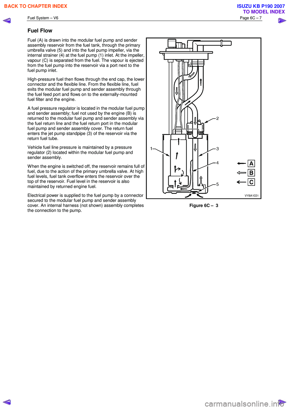
Fuel Flow
Fuel (A) is drawn into the modular fuel pump and sender
assembly reservoir from the fuel tank, through the primary
umbrella valve (5) and into the fuel pump impeller, via the
internal strainer (4) at the fuel pump (1) inlet. At the impeller,
vapour (C) is separated from the fuel. The vapour is ejected
from the fuel pump into the reservoir via a port next to the
fuel pump inlet.
High-pressure fuel then flows through the end cap, the lower
connector and the flexible line. From the flexible line, fuel
exits the modular fuel pump and sender assembly through
the fuel feed port and flows on to the externally-mounted
fuel filter and the engine.
A fuel pressure regulator is located in the modular fuel pump
and sender assembly; fuel not used by the engine (B) is
returned to the modular fuel pump and sender assembly via
the fuel return line and the fuel return port in the modular
fuel pump and sender assembly cover. The return fuel
enters the jet pump standpipe (3) of the reservoir via the
return fuel tube.
Vehicle fuel line pressure is maintained by a pressure
regulator (2) located within the modular fuel pump and
sender assembly.
W hen the engine is switched off, the reservoir remains full of
fuel, due to the action of the primary umbrella valve. At high
fuel levels, fuel tank overflow enters the reservoir over the
top of the reservoir. Fuel level in the reservoir is also
maintained by returned engine fuel.
Electrical power is supplied to the fuel pump by a connector
secured to the modular fuel pump and sender assembly
cover. An internal harness (not shown) assembly completes
the connection to the pump.
Figure 6C – 3
BACK TO CHAPTER INDEX
TO MODEL INDEX
ISUZU KB P190 2007
Page 3211 of 6020
Fuel System – V6 Page 6C – 9
A small amount of fuel may be released when
connecting the fuel pressure gauge to the fuel
pressure test point. Cover the fittings with a
shop towel to absorb any fuel spillage before
connecting the fuel pressure gauge. After the
fuel pressure test procedure, place the soiled
towel in an approved container for disposal.
3 At the fuel pressure test point, remove the Schrader valve sealing cap.
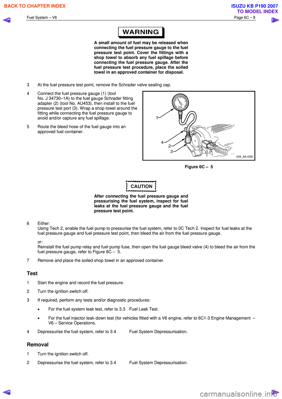
4 Connect the fuel pressure gauge (1) (tool No. J 34730–1A) to the fuel gauge Schrader fitting
adapter (2) (tool No. AU453), then install to the fuel
pressure test port (3). W rap a shop towel around the
fitting while connecting the fuel pressure gauge to
avoid and/or capture any fuel spillage.
5 Route the bleed hose of the fuel gauge into an approved fuel container.
Figure 6C – 5
After connecting the fuel pressure gauge and
pressurising the fuel system, inspect for fuel
leaks at the fuel pressure gauge and the fuel
pressure test point.
6 Either: Using Tech 2, enable the fuel pump to pressurise the fuel system, refer to 0C Tech 2. Inspect for fuel leaks at the
fuel pressure gauge and fuel pressure test point, then bleed the air from the fuel pressure gauge.
or: Reinstall the fuel pump relay and fuel pump fuse, then open the fuel gauge bleed valve (4) to bleed the air from the
fuel pressure gauge, refer to Figure 6C – 5.
7 Remove and place the soiled shop towel in an approved container.
Test
1 Start the engine and record the fuel pressure.
2 Turn the ignition switch off.
3 If required, perform any tests and/or diagnostic procedures:
• For the fuel system leak test, refer to 3.3 Fuel Leak Test.
• For the fuel injector leak-down test (for vehicles fitted with a V6 engine, refer to 6C1-3 Engine Management –
V6 – Service Operations.
4 Depressurise the fuel system, refer to 3.4 Fuel System Depressurisation.
Removal
1 Turn the ignition switch off.
2 Depressurise the fuel system, refer to 3.4 Fuel System Depressurisation.
BACK TO CHAPTER INDEX
TO MODEL INDEX
ISUZU KB P190 2007
Page 3213 of 6020
Fuel System – V6 Page 6C – 11
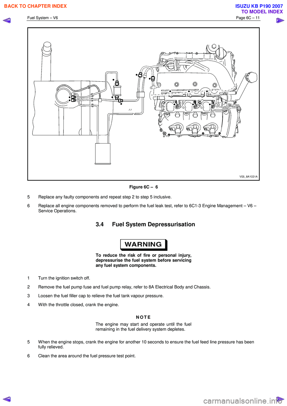
Figure 6C – 6
5 Replace any faulty components and repeat step 2 to step 5 inclusive.
6 Replace all engine components removed to perform the fuel leak test, refer to 6C1-3 Engine Management – V6 – Service Operations.
3.4 Fuel System Depressurisation
To reduce the risk of fire or personal injury,
depressurise the fuel system before servicing
any fuel system components.
1 Turn the ignition switch off.
2 Remove the fuel pump fuse and fuel pump relay, refer to 8A Electrical Body and Chassis.
3 Loosen the fuel filler cap to relieve the fuel tank vapour pressure.
4 W ith the throttle closed, crank the engine.
NOTE
The engine may start and operate until the fuel
remaining in the fuel delivery system depletes.
5 W hen the engine stops, crank the engine for another 10 seconds to ensure the fuel feed line pressure has been fully relieved.
6 Clean the area around the fuel pressure test point.
BACK TO CHAPTER INDEX
TO MODEL INDEX
ISUZU KB P190 2007