2007 ISUZU KB P190 fuel cap
[x] Cancel search: fuel capPage 1626 of 6020
ENGINE CONTROL SYSTEM (4JK1/4JJ1) 6E-9
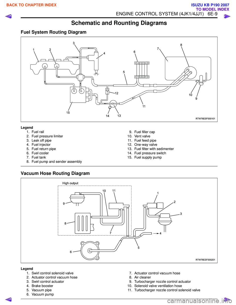
Schematic and Rounting Diagrams
Fuel System Routing Diagram
Legend1. Fuel rail
2. Fuel pressure limiter
3. Leak off pipe
4. Fuel injector
5. Fuel return pipe
6. Fuel cooler
7. Fuel tank
8. Fuel pump and sender assembly 9. Fuel filler cap
10. Vent valve 11. Fuel feed pipe
12. One-way valve
13. Fuel filter with sedimenter
14. Fuel pressure switch
15. Fuel supply pump
Vacuum Hose Routing Diagram
Legend
1. Swirl control solenoid valve
2. Actuator control vacuum hose
3. Swirl control actuator
4. Brake booster
5. Vacuum pipe
6. Vacuum pump 7. Actuator control vacuum hose
8. Air cleaner
9. Turbocharger nozzle control actuator
10. Solenoid valve ventilation hose 11. Turbocharger nozzle control solenoid valve
RTW76ESF000101
12 3
4
5
117
8
9
10
14
13
12
15
6
RTW76ESF000201
1 2
4
5
6
9
8
3
7
11
High output10
BACK TO CHAPTER INDEX
TO MODEL INDEX
ISUZU KB P190 2007
Page 1928 of 6020
ENGINE CONTROL SYSTEM (4JK1/4JJ1) 6E-311
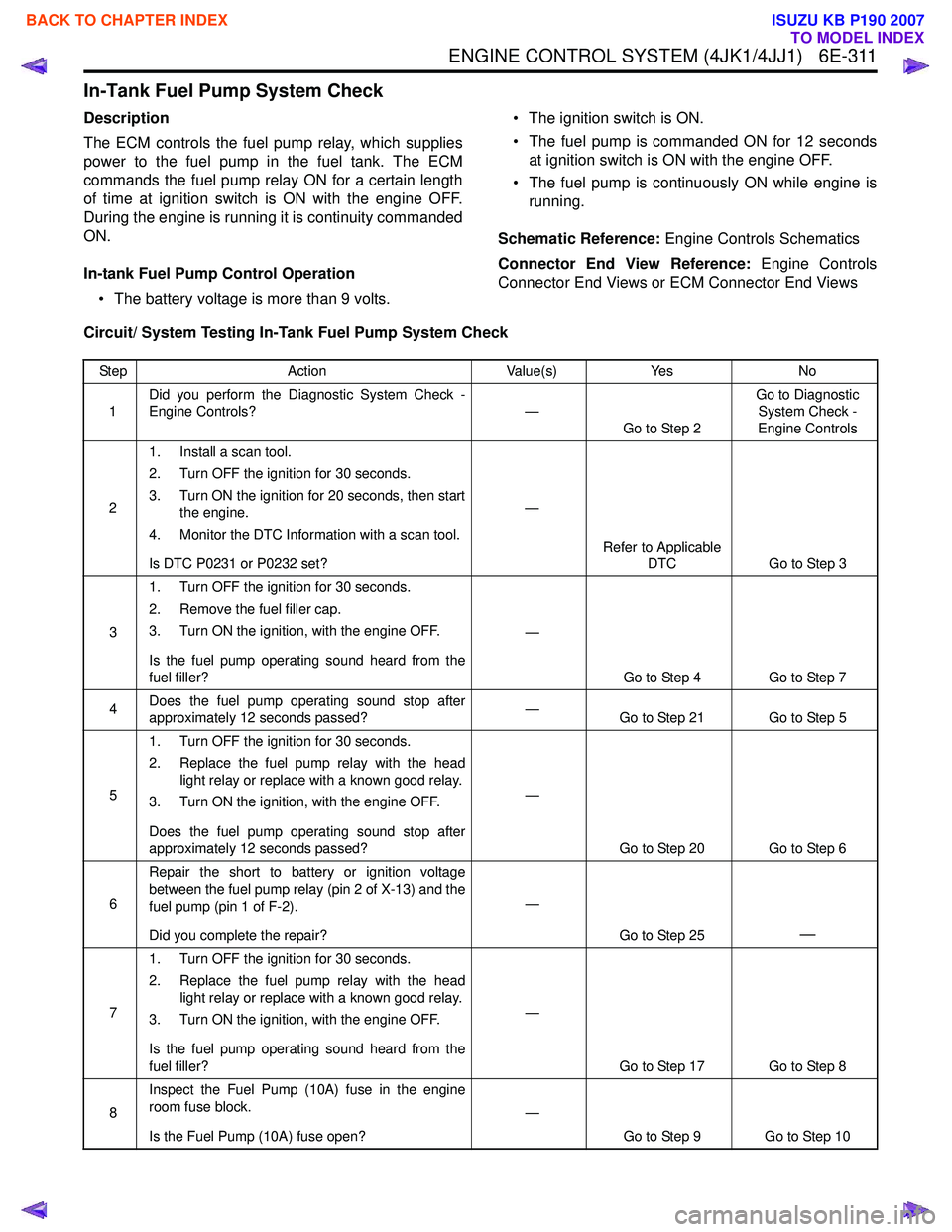
In-Tank Fuel Pump System Check
Description
The ECM controls the fuel pump relay, which supplies
power to the fuel pump in the fuel tank. The ECM
commands the fuel pump relay ON for a certain length
of time at ignition switch is ON with the engine OFF.
During the engine is running it is continuity commanded
ON.
In-tank Fuel Pump Control Operation • The battery voltage is more than 9 volts. • The ignition switch is ON.
• The fuel pump is commanded ON for 12 seconds at ignition switch is ON with the engine OFF.
• The fuel pump is continuously ON while engine is running.
Schematic Reference: Engine Controls Schematics
Connector End View Reference: Engine Controls
Connector End Views or ECM Connector End Views
Circuit/ System Testing In-Tank Fuel Pump System Check
Step Action Value(s)Yes No
1 Did you perform the Diagnostic System Check -
Engine Controls? —
Go to Step 2 Go to Diagnostic
System Check -
Engine Controls
2 1. Install a scan tool.
2. Turn OFF the ignition for 30 seconds.
3. Turn ON the ignition for 20 seconds, then start the engine.
4. Monitor the DTC Information with a scan tool.
Is DTC P0231 or P0232 set? —
Refer to Applicable DTC Go to Step 3
3 1. Turn OFF the ignition for 30 seconds.
2. Remove the fuel filler cap.
3. Turn ON the ignition, with the engine OFF.
Is the fuel pump operating sound heard from the
fuel filler? —
Go to Step 4 Go to Step 7
4 Does the fuel pump operating sound stop after
approximately 12 seconds passed? —
Go to Step 21 Go to Step 5
5 1. Turn OFF the ignition for 30 seconds.
2. Replace the fuel pump relay with the head light relay or replace with a known good relay.
3. Turn ON the ignition, with the engine OFF.
Does the fuel pump operating sound stop after
approximately 12 seconds passed? —
Go to Step 20 Go to Step 6
6 Repair the short to battery or ignition voltage
between the fuel pump relay (pin 2 of X-13) and the
fuel pump (pin 1 of F-2).
Did you complete the repair? —
Go to Step 25
—
71. Turn OFF the ignition for 30 seconds.
2. Replace the fuel pump relay with the head light relay or replace with a known good relay.
3. Turn ON the ignition, with the engine OFF.
Is the fuel pump operating sound heard from the
fuel filler? —
Go to Step 17 Go to Step 8
8 Inspect the Fuel Pump (10A) fuse in the engine
room fuse block.
Is the Fuel Pump (10A) fuse open? —
Go to Step 9 Go to Step 10
BACK TO CHAPTER INDEX
TO MODEL INDEX
ISUZU KB P190 2007
Page 1966 of 6020
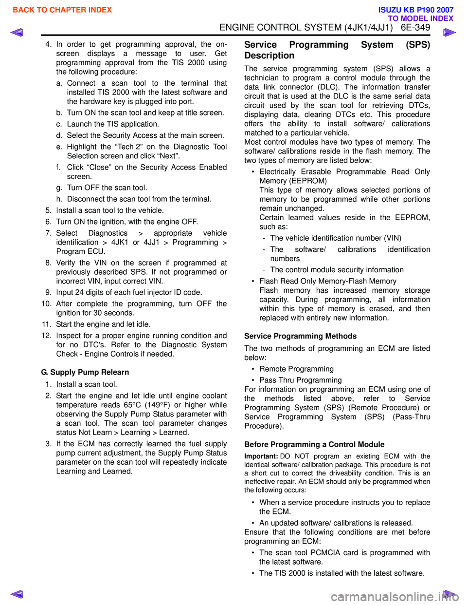
ENGINE CONTROL SYSTEM (4JK1/4JJ1) 6E-349
4. In order to get programming approval, the on-screen displays a message to user. Get
programming approval from the TIS 2000 using
the following procedure:
a. Connect a scan tool to the terminal that installed TIS 2000 with the latest software and
the hardware key is plugged into port.
b. Turn ON the scan tool and keep at title screen.
c. Launch the TIS application.
d. Select the Security Access at the main screen.
e. Highlight the “Tech 2” on the Diagnostic Tool Selection screen and click “Next”.
f. Click “Close” on the Security Access Enabled screen.
g. Turn OFF the scan tool.
h. Disconnect the scan tool from the terminal.
5. Install a scan tool to the vehicle.
6. Turn ON the ignition, with the engine OFF.
7. Select Diagnostics > appropriate vehicle identification > 4JK1 or 4JJ1 > Programming >
Program ECU.
8. Verify the VIN on the screen if programmed at previously described SPS. If not programmed or
incorrect VIN, input correct VIN.
9. Input 24 digits of each fuel injector ID code.
10. After complete the programming, turn OFF the ignition for 30 seconds.
11. Start the engine and let idle.
12. Inspect for a proper engine running condition and for no DTC's. Refer to the Diagnostic System
Check - Engine Controls if needed.
G. Supply Pump Relearn 1. Install a scan tool.
2. Start the engine and let idle until engine coolant temperature reads 65 °C (149 °F) or higher while
observing the Supply Pump Status parameter with
a scan tool. The scan tool parameter changes
status Not Learn > Learning > Learned.
3. If the ECM has correctly learned the fuel supply pump current adjustment, the Supply Pump Status
parameter on the scan tool will repeatedly indicate
Learning and Learned.Service Programming System (SPS)
Description
The service programming system (SPS) allows a
technician to program a control module through the
data link connector (DLC). The information transfer
circuit that is used at the DLC is the same serial data
circuit used by the scan tool for retrieving DTCs,
displaying data, clearing DTCs etc. This procedure
offers the ability to install software/ calibrations
matched to a particular vehicle.
Most control modules have two types of memory. The
software/ calibrations reside in the flash memory. The
two types of memory are listed below:
• Electrically Erasable Programmable Read Only Memory (EEPROM)
This type of memory allows selected portions of
memory to be programmed while other portions
remain unchanged.
Certain learned values reside in the EEPROM,
such as:
- The vehicle identification number (VIN)
- The software/ calibrations identification numbers
- The control module security information
• Flash Read Only Memory-Flash Memory Flash memory has increased memory storage
capacity. During programming, all information
within this type of memory is erased, and then
replaced with entirely new information.
Service Programming Methods
The two methods of programming an ECM are listed
below:
• Remote Programming
• Pass Thru Programming
For information on programming an ECM using one of
the methods listed above, refer to Service
Programming System (SPS) (Remote Procedure) or
Service Programming System (SPS) (Pass-Thru
Procedure).
Before Programming a Control Module
Important: DO NOT program an existing ECM with the
identical software/ calibration package. This procedure is not
a short cut to correct the driveability condition. This is an
ineffective repair. An ECM should only be programmed when
the following occurs:
• When a service procedure instructs you to replace the ECM.
• An updated software/ calibrations is released.
Ensure that the following conditions are met before
programming an ECM:
• The scan tool PCMCIA card is programmed with the latest software.
• The TIS 2000 is installed with the latest software.
BACK TO CHAPTER INDEX
TO MODEL INDEX
ISUZU KB P190 2007
Page 2025 of 6020
ENGINE MECHANICAL (C24SE) 6A-11
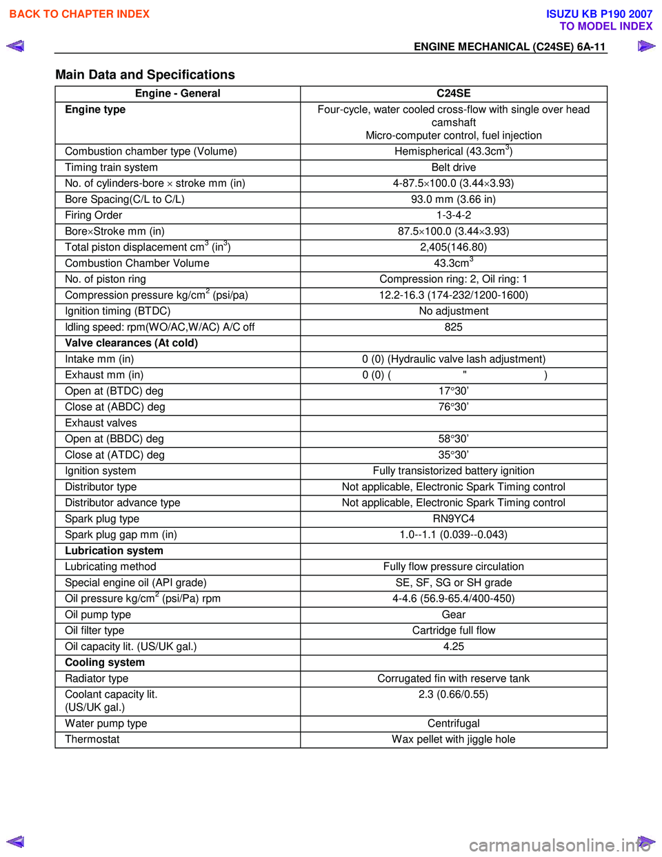
Main Data and Specifications
Engine - General C24SE
Engine type Four-cycle, water cooled cross-flow with single over head
camshaft
Micro-computer control, fuel injection
Combustion chamber type (Volume) Hemispherical (43.3cm3)
Timing train system Belt drive
No. of cylinders-bore × stroke mm (in) 4-87.5 ×100.0 (3.44 ×3.93)
Bore Spacing(C/L to C/L) 93.0 mm (3.66 in)
Firing Order 1-3-4-2
Bore×Stroke mm (in) 87.5 ×100.0 (3.44 ×3.93)
Total piston displacement cm3 (in3) 2,405(146.80)
Combustion Chamber Volume 43.3cm3
No. of piston ring Compression ring: 2, Oil ring: 1
Compression pressure kg/cm2 (psi/pa) 12.2-16.3 (174-232/1200-1600)
Ignition timing (BTDC) No adjustment
Idling speed: rpm(W O/AC,W /AC) A/C off 825
Valve clearances (At cold)
Intake mm (in) 0 (0) (Hydraulic valve lash adjustment)
Exhaust mm (in) 0 (0) ( " )
Open at (BTDC) deg 17°30’
Close at (ABDC) deg 76°30’
Exhaust valves
Open at (BBDC) deg 58°30’
Close at (ATDC) deg 35°30’
Ignition system Fully transistorized battery ignition
Distributor type Not applicable, Electronic Spark Timing control
Distributor advance type Not applicable, Electronic Spark Timing control
Spark plug type RN9YC4
Spark plug gap mm (in) 1.0--1.1 (0.039--0.043)
Lubrication system
Lubricating method Fully flow pressure circulation
Special engine oil (API grade) SE, SF, SG or SH grade
Oil pressure kg/cm2 (psi/Pa) rpm 4-4.6 (56.9-65.4/400-450)
Oil pump type Gear
Oil filter type Cartridge full flow
Oil capacity lit. (US/UK gal.) 4.25
Cooling system
Radiator type Corrugated fin with reserve tank
Coolant capacity lit.
(US/UK gal.) 2.3 (0.66/0.55)
W ater pump type
Centrifugal
Thermostat W ax pellet with jiggle hole
BACK TO CHAPTER INDEX
TO MODEL INDEX
ISUZU KB P190 2007
Page 2026 of 6020
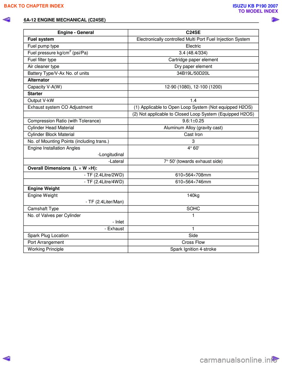
6A-12 ENGINE MECHANICAL (C24SE)
Engine - General C24SE
Fuel system Electronically controlled Multi Port Fuel Injection System
Fuel pump type Electric
Fuel pressure kg/cm2 (psi/Pa) 3.4 (48.4/334)
Fuel filter type Cartridge paper element
Air cleaner type Dry paper element
Battery Type/V-Ax No. of units 34B19L/50D20L
Alternator
Capacity V-A(W ) 12-90 (1080), 12-100 (1200)
Starter
Output V-kW 1.4
Exhaust system CO Adjustment (1) Applicable to Open Loop System (Not equipped H2OS)
(2) Not applicable to Closed Loop System (Equipped H2OS)
Compression Ratio (with Tolerance) 9.6:1±0.25
Cylinder Head Material Aluminum Alloy (gravity cast)
Cylinder Block Material Cast Iron
No. of Mounting Points (including trans.) 3
Engine Installation Angles
-Longitudinal 4
° 60'
-Lateral 7° 50' (towards exhaust side)
Overall Dimensions (L ×
××
×
W ×
××
×
H):
- TF (2.4Litre/2W D)610×564 ×708mm
- TF (2.4Litre/4W D) 610×564 ×746mm
Engine Weight
Engine W eight
- TF (2.4Liter/Man) 140kg
Camshaft Type
SOHC
No. of Valves per Cylinder
- Inlet1
- Exhaust
1
Spark Plug Location Side
Port Arrangement Cross Flow
W orking Principle Spark Ignition 4-stroke
BACK TO CHAPTER INDEX
TO MODEL INDEX
ISUZU KB P190 2007
Page 2119 of 6020
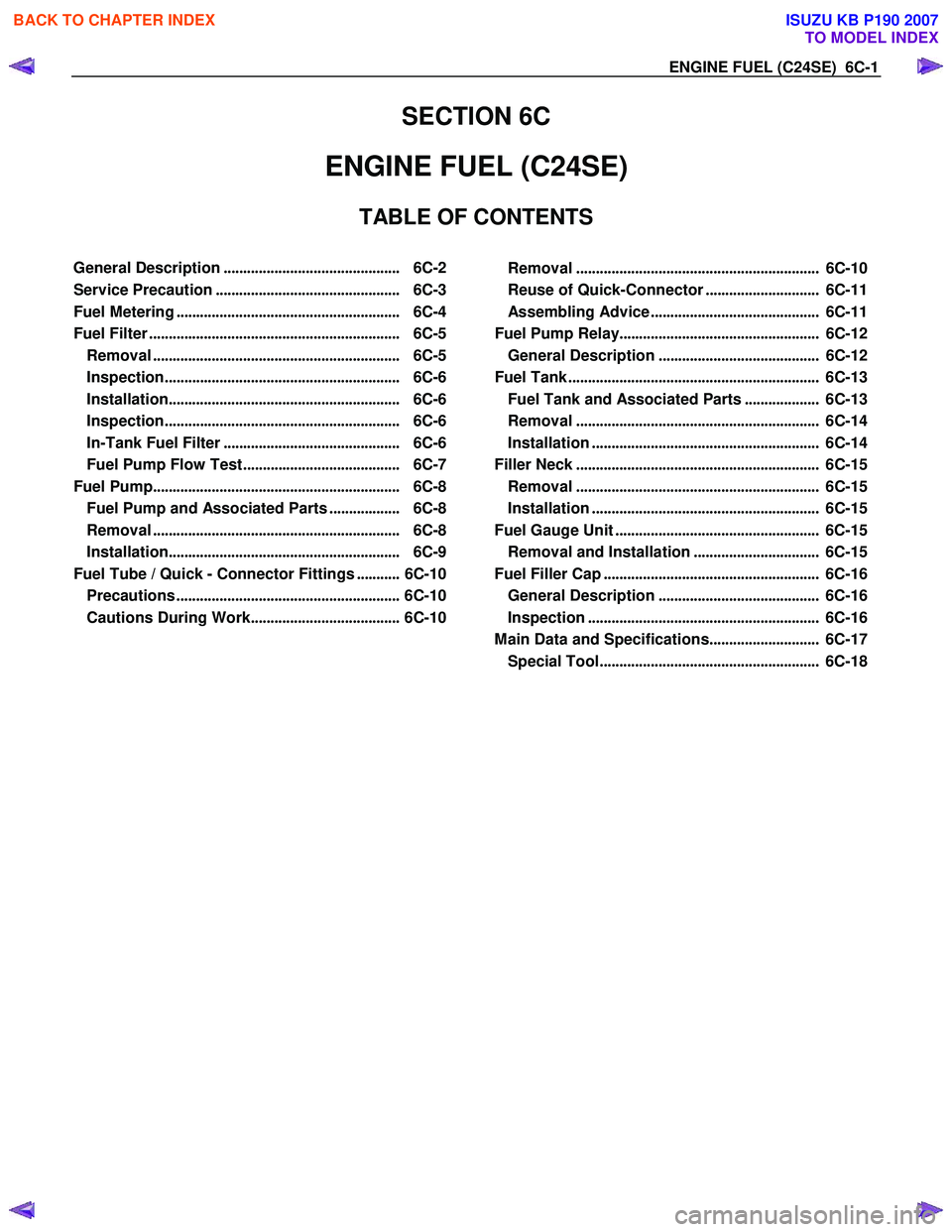
ENGINE FUEL (C24SE) 6C-1
SECTION 6C
ENGINE FUEL (C24SE)
TABLE OF CONTENTS
General Description ............................................. 6C-2
Service Precaution ............................................... 6C-3
Fuel Metering ......................................................... 6C-4
Fuel Filter ................................................................ 6C-5
Removal ............................................................... 6C-5
Inspection ............................................................ 6C-6
Installation ........................................................... 6C-6
Inspection ............................................................ 6C-6
In-Tank Fuel Filter ............................................. 6C-6
Fuel Pump Flow Test ........................................ 6C-7
Fuel Pump ............................................................... 6C-8
Fuel Pump and Associated Parts .................. 6C-8
Removal ............................................................... 6C-8
Installation ........................................................... 6C-9
Fuel Tube / Quick - Connector Fittings ........... 6C-10
Precautions ......................................................... 6C-10
Cautions During Work ...................................... 6C-10
Removal .............................................................. 6C-10
Reuse of Quick-Connector ............................. 6C-11
Assembling Advice ........................................... 6C-11
Fuel Pump Relay ................................................... 6C-12
General Description ......................................... 6C-12
Fuel Tank ................................................................ 6C-13
Fuel Tank and Associated Parts ................... 6C-13
Removal .............................................................. 6C-14
Installation .......................................................... 6C-14
Filler Neck .............................................................. 6C-15
Removal .............................................................. 6C-15
Installation .......................................................... 6C-15
Fuel Gauge Unit .................................................... 6C-15
Removal and Installation ................................ 6C-15
Fuel Filler Cap ....................................................... 6C-16
General Description ......................................... 6C-16
Inspection ........................................................... 6C-16
Main Data and Specifications ............................ 6C-17
Special Tool ........................................................ 6C-18
BACK TO CHAPTER INDEX
TO MODEL INDEX
ISUZU KB P190 2007
Page 2121 of 6020
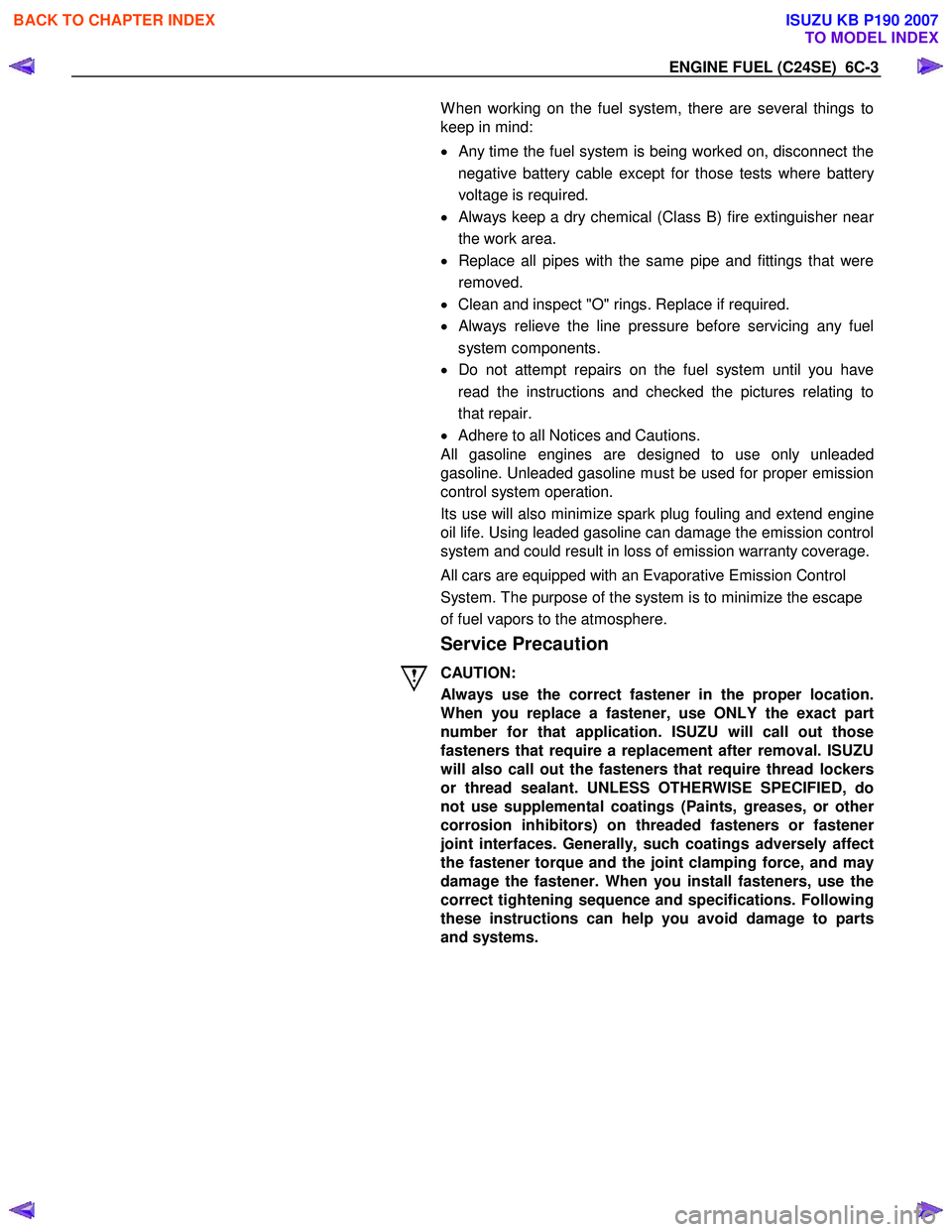
ENGINE FUEL (C24SE) 6C-3
W hen working on the fuel system, there are several things to
keep in mind:
•
Any time the fuel system is being worked on, disconnect the
negative battery cable except for those tests where batter
y
voltage is required.
•
Always keep a dry chemical (Class B) fire extinguisher near
the work area.
• Replace all pipes with the same pipe and fittings that were
removed.
• Clean and inspect "O" rings. Replace if required.
•
Always relieve the line pressure before servicing any fuel
system components.
• Do not attempt repairs on the fuel system until you have
read the instructions and checked the pictures relating to
that repair.
• Adhere to all Notices and Cautions.
All gasoline engines are designed to use only unleaded
gasoline. Unleaded gasoline must be used for proper emission
control system operation.
Its use will also minimize spark plug fouling and extend engine
oil life. Using leaded gasoline can damage the emission control
system and could result in loss of emission warranty coverage.
All cars are equipped with an Evaporative Emission Control
System. The purpose of the system is to minimize the escape
of fuel vapors to the atmosphere.
Service Precaution
CAUTION:
Always use the correct fastener in the proper location.
When you replace a fastener, use ONLY the exact part
number for that application. ISUZU will call out those
fasteners that require a replacement after removal. ISUZU
will also call out the fasteners that require thread lockers
or thread sealant. UNLESS OTHERWISE SPECIFIED, do
not use supplemental coatings (Paints, greases, or othe
r
corrosion inhibitors) on threaded fasteners or fastene
r
joint interfaces. Generally, such coatings adversely affect
the fastener torque and the joint clamping force, and may
damage the fastener. When you install fasteners, use the
correct tightening sequence and specifications. Following
these instructions can help you avoid damage to parts
and systems.
BACK TO CHAPTER INDEX
TO MODEL INDEX
ISUZU KB P190 2007
Page 2124 of 6020
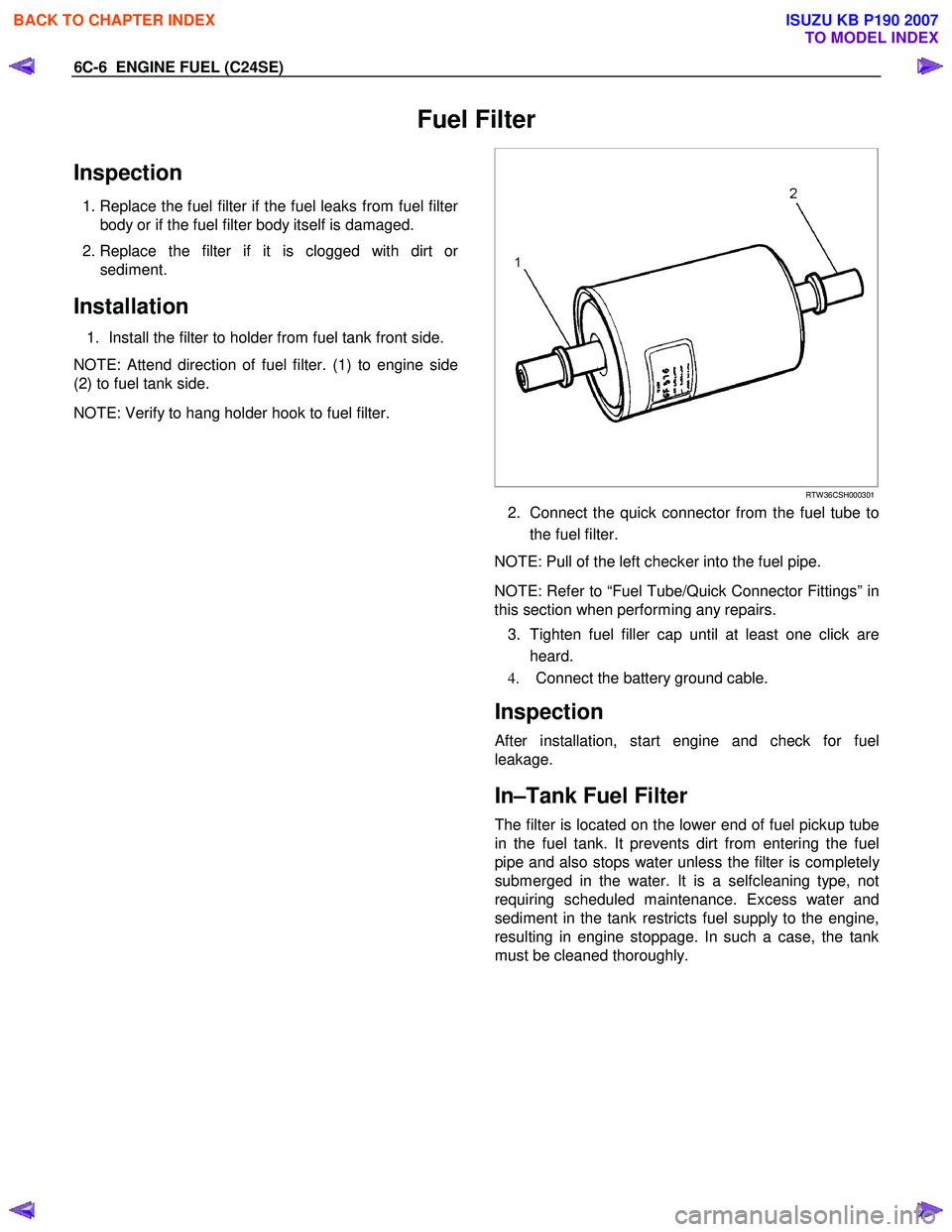
6C-6 ENGINE FUEL (C24SE)
Fuel Filter
Inspection
1. Replace the fuel filter if the fuel leaks from fuel filter
body or if the fuel filter body itself is damaged.
2. Replace the filter if it is clogged with dirt o
r
sediment.
Installation
1. Install the filter to holder from fuel tank front side.
NOTE: Attend direction of fuel filter. (1) to engine side
(2) to fuel tank side.
NOTE: Verify to hang holder hook to fuel filter.
RTW 36CSH000301
2. Connect the quick connector from the fuel tube to
the fuel filter.
NOTE: Pull of the left checker into the fuel pipe.
NOTE: Refer to “Fuel Tube/Quick Connector Fittings” in
this section when performing any repairs.
3. Tighten fuel filler cap until at least one click are heard.
4. Connect the battery ground cable.
Inspection
After installation, start engine and check for fuel
leakage.
In–Tank Fuel Filter
The filter is located on the lower end of fuel pickup tube
in the fuel tank. It prevents dirt from entering the fuel
pipe and also stops water unless the filter is completel
y
submerged in the water. It is a selfcleaning type, not
requiring scheduled maintenance. Excess water and
sediment in the tank restricts fuel supply to the engine,
resulting in engine stoppage. In such a case, the tank
must be cleaned thoroughly.
BACK TO CHAPTER INDEX
TO MODEL INDEX
ISUZU KB P190 2007