Page 556 of 6020
, then
loosen the nut to the full.
Tighten the hub nut at the value given below, u")
4C1-52 FRONT WHEEL DRIVE
Preload Adjustment
Tighten the hub nut at 29.4 N⋅m (3 kgf ⋅m / 2 1.7 lb·ft), then
loosen the nut to the full.
Tighten the hub nut at the value given below, using a spring
scale on the wheel pin.
Bearing Preload N (kgf/lb)
New bearing and New oil seal 22 - 27
(2.2 - 2.8 / 4.9 - 6.2)
Used bearing and New oil seal 1
4 - 20
( 1 .4 - 2.0 / 3. 1 - 4.5)
If the measured bearing preload is outside the specifications,
adjust it by loosening or tightening the bearing nut.
9. Lock Washer
Turn the side with larger diameter of the tapered bore to the
vehicle outer side, and attach the washer.
If the bolt holes in the lock plate are not aligned with the
corresponding holes in the nut, reverse the lock plate.
If the bolt holes are still out of alignment, turn in the nut just
enough to obtain alignment,. Screw is to be fastened tightly so
its head may come lower than the surface of the washer.
10. Flange (4×4 model only)
Apply adhesive (LOCTITE 5 15 or equivalent) to both joining
flange faces then install hub flange.
11. Snap ring, shims (4×4 model only)
Adjust the clearance between the flange and the snap ring.
Clearance mm(in) 0 - 0.2 (0 - 0.008)
Adjust shims available mm(in)
0.2, 0.3, 0.5, 1.0
(0.008, 0.0 12, 0.020, 0.039)
RTW 440SH00090 1
13. Bolt
Torque N ⋅m (kgf ⋅m/lb ⋅ft
)
59 (6.0 / 43)
• Refer to SECTION 3E “W HEELS AND TIRES” for wheel
install procedure.
BACK TO CHAPTER INDEX
TO MODEL INDEX
ISUZU KB P190 2007
Page 557 of 6020
FRONT WHEEL DRIVE 4C1-53
FRONT HUB AND DISC
(4 ×
××
×
4 Manual Locking Hub Model)
DISASSEMBLY
Refer to SECTION 3E “WHEELS AND TIRES” for wheel removal procedure
RTW 440LF00030 1
Disassembly Steps
� 1 . Bolt
2. Cover assembly
3. Snap ring and shim
4. Body assembly
5. Lock washer
� 6. Hub nut
� 7. Hub and disc assembly
8. Outer bearing
9. Oil seal
10. Inner bearing
11. ABS sensor rotor
� 1 2. Bolt
� 13. W heel pin
�
1 4. Clutch assembly
15. Snap ring
16. Knob
17. Compression spring
18. Follower
� 1 9. Retaining spring
20. X-ring
2 1. Snap ring
22. Inner assembly
23. Snap ring
24. Ring
25. Spacer
BACK TO CHAPTER INDEX
TO MODEL INDEX
ISUZU KB P190 2007
Page 560 of 6020
4C1-56 FRONT WHEEL DRIVE
INSPECTION AND REPAIR
Make necessary correction or parts replacement if wear, damage or any other abnormal conditions are found
through inspection.
For inspection and servicing of disc caliper, and relative parts, and ABS parts, refer to Section Brakes.
• Hub
• Hub bearing, oil seal
• Knuckle spindle
• Disc
• Caliper
• ABS sensor rotor
• Cap, Hub flange, Shim, Snap ring
• Free wheeling hub parts (Option)
• Clutch, Knob, follower, inner, ring and
spring
Visual Check
Check the following parts for wear, damage or other abnormal
conditions.
BACK TO CHAPTER INDEX
TO MODEL INDEX
ISUZU KB P190 2007
Page 561 of 6020
FRONT WHEEL DRIVE 4C1-57
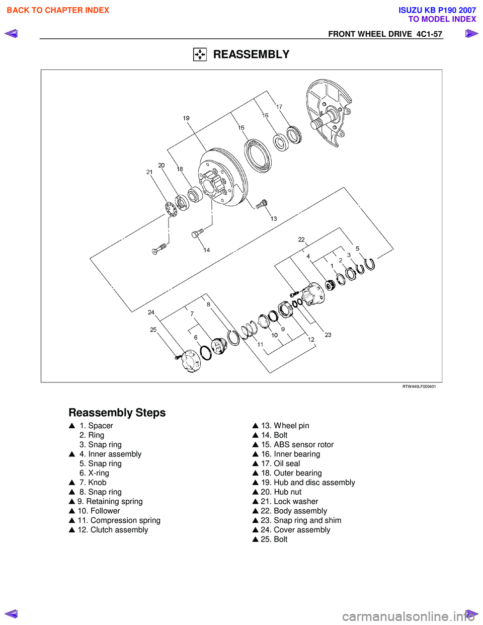
REASSEMBLY
RTW 440LF00040 1
Reassembly Steps
� 1 . Spacer
2. Ring
3. Snap ring
� 4. Inner assembly
5. Snap ring
6. X-ring
� 7. Knob
� 8. Snap ring
� 9. Retaining spring
� 1 0. Follower
� 11 . Compression spring
� 1 2. Clutch assembly
�
1 3. W heel pin
� 1 4. Bolt
� 1 5. ABS sensor rotor
� 1 6. Inner bearing
� 1 7. Oil seal
� 1 8. Outer bearing
� 1 9. Hub and disc assembly
� 20. Hub nut
� 21. Lock washer
� 22. Body assembly
� 23. Snap ring and shim
� 24. Cover assembly
� 25. Bolt
BACK TO CHAPTER INDEX
TO MODEL INDEX
ISUZU KB P190 2007
Page 564 of 6020
4C1-60 FRONT WHEEL DRIVE
RTW 74CSH000301
17. Oil Seal
Installer : 5-8840-2854-0
Grip : 5-8840-0007-0
Apply grease (Besco L-2 or equivalent) to the lip portion.
Discard the used oil seal and install a new one.
RTW 44CSH00020 1
18. Outer bearing
Outer race ; outer bearing
Install the outer race by driving it into the hub.
Installer : 5-8522-0054-0
Grip : 5-8840-0007-0
19. Hub and Disc Assembly
( 1 ) Apply grease in the hub.
(2) Apply grease (Besco L-2 or equivalent) to the outer and inner bearing. g(oz)
Hub 35 (1.23)
Outer bearing 10 (0.35)
Inner bearing 15 (0.53)
20. Hub Nut
( 1 ) Turn the place where there is a chamfer in the tapped hole
to the outer side, and attach the nut.
W rench : 5-8840-2 117-0
BACK TO CHAPTER INDEX
TO MODEL INDEX
ISUZU KB P190 2007
Page 565 of 6020
, then loosen
the nut to the full.
Tighten the hub nut at the value given below, us")
FRONT WHEEL DRIVE 4C1-61
Preload Adjustment
Tighten the hub nut at 29 N⋅m (3.0 kgf ⋅m / 22 lb ⋅ft), then loosen
the nut to the full.
Tighten the hub nut at the value given below, using a spring
scale on the wheel pin.
Bearing Preload N (kgf/lb)
New bearing and New oil seal 22 - 27
(2.2 - 2.8 / 4.9 - 6.2)
Used bearing and New oil seal 1
4 - 20
( 1 .4 - 2.0 / 3. 1 - 4.5)
If the measured bearing preload is outside the specifications,
adjust it by loosening or tightening the bearing nut.
21. Lock Washer
Turn the side with larger diameter of the tapered bore to the
vehicle outer side, and attach the washer.
If the bolt holes in the lock plate are not aligned with the
corresponding holes in the nut, reverse the lock plate.
If the bolt holes are still out of alignment, turn in the nut just
enough to obtain alignment,. Screw is to be fastened tightly so
its head may come lower than the surface of the washer.
22. Body Assembly
Apply adhesive (Loctite 5 15 or equivalent) to the both joining
faces.
23. Snap Ring and Shims
Adjust the clearance between the free wheeling hub body and
the snap ring.
Clearance mm(in) 0 - 0.2 (0 - 0.08)
Adjust Shims Available mm(in)
0.2, 0.3, 0.5, 1.0
(0.008, 0.0 11, 0.020, 0.039)
BACK TO CHAPTER INDEX
TO MODEL INDEX
ISUZU KB P190 2007
Page 567 of 6020
FRONT WHEEL DRIVE 4C1-63
TROUBLESHOOTING
Refer to this Section to quickly diagnose and repair front axle problems. Each troubleshooting chart has three
headings arranged from left to right.
(1 ) Checkpoint (2) Trouble Cause (3) Countermeasure
This Section is divided into ten sub-sections:
4 × 2 Model
1. W anders and pulls
2. Front wheel shimmy
4 × 4 Model
1. Oil leak at front axle
2. Oil leak at pinion shaft
3. Noises in front axle drive shaft joint
4. Noises in front axle
5. W anders and pulls
6. Front wheel shimmy
Propeller shaft
1 . Noise
2. Vibration
BACK TO CHAPTER INDEX
TO MODEL INDEX
ISUZU KB P190 2007
Page 570 of 6020
4C1-66 FRONT WHEEL DRIVE
4× 4 MODEL
1. OIL LEAK AT FRONT AXLE
Checkpoint Trouble Cause Countermeasure
Front axle housingRepair or replaceCracked
Replace the oil sealW orn or defective oil seal
NG
NG
OKOil seal
2. OIL LEAK AT PINION SHAFT
Oil sealReplace the oil sealW orn or defective
Correct the oil levelToo much gear oil
NG
NG
OKGear oil level
Pinion flangeTighten or replaceLoose or damaged
NG
OK
3. NOISES IN FRONT AXLE DRIVE SHAFT JOINT
Replace the drive shaft joints
and bellows
Broken or worn
NG
Drive shaft joints and bellows
(UJ and DOJ)
BACK TO CHAPTER INDEX
TO MODEL INDEX
ISUZU KB P190 2007

DISASSEMBLY
Refer to SECTION 3E “WHEELS AND TIRES” for wheel removal procedure
RTW 440LF000")

 to the lip portion.
Discard the used oil seal")

