2007 ISUZU KB P190 Wiring
[x] Cancel search: WiringPage 3136 of 6020
Engine Cooling – V6 Engine Page 6B1–1
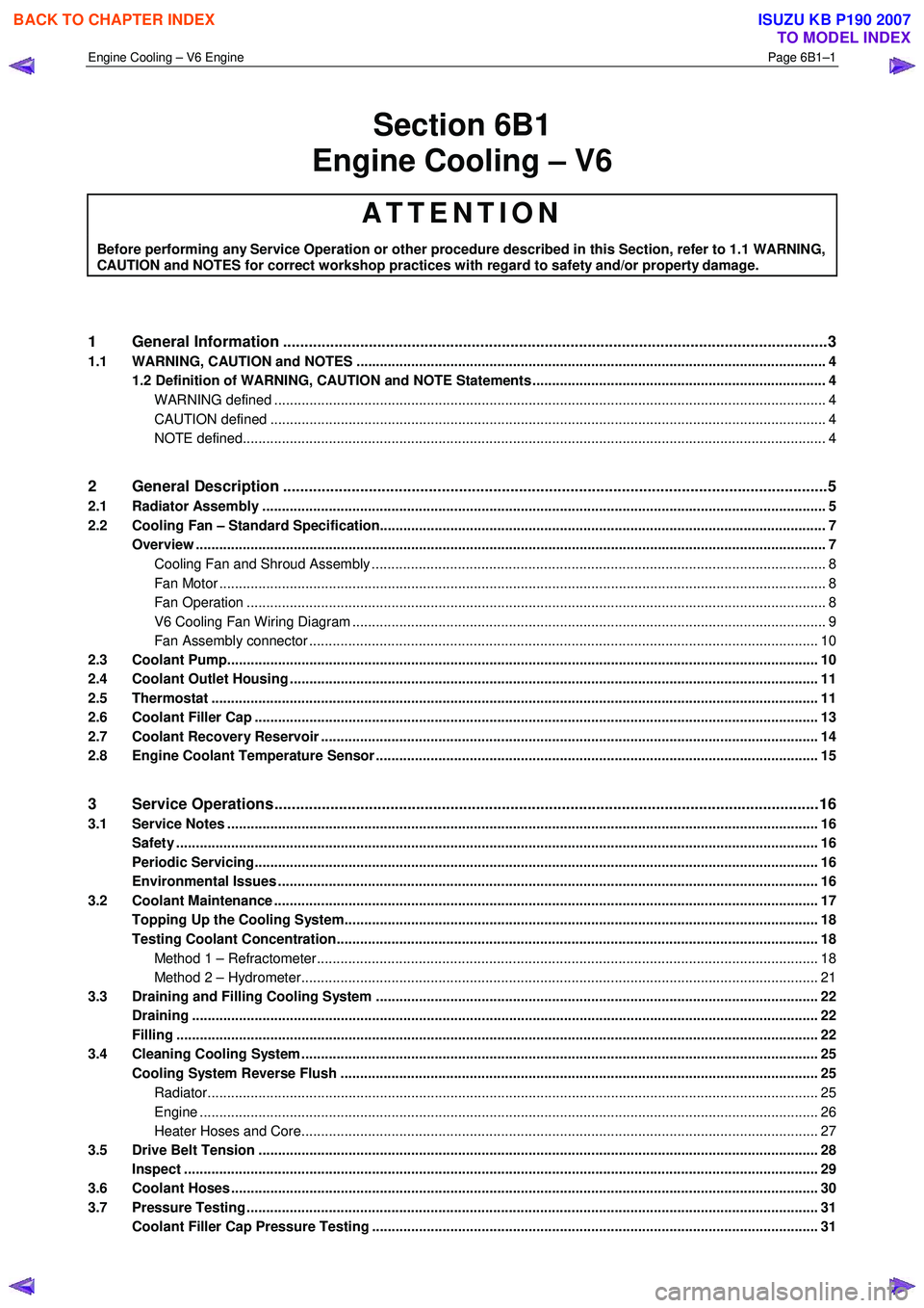
Section 6B1
Engine Cooling – V6
ATTENTION
Before performing any Service Operation or other procedure described in this Section, refer to 1.1 WARNING,
CAUTION and NOTES for correct workshop practices with regard to safety and/or property damage.
1 General Information ............................................................................................................ ...................3
1.1 WARNING, CAUTION and NOTES ..................................................................................................... ................... 4
1.2 Definition of WARNING, CAUTION and NOTE Statements ......................................................................... .. 4
WARNING defined ............................................................................................................................................. 4
CAUTION defined .............................................................................................................................................. 4
NOTE defined..................................................................................................................................................... 4
2 General Description ............................................................................................................ ...................5
2.1 Radiator Assembly .............................................................................................................. .................................. 5
2.2 Cooling Fan – Standard Specification.................................................................................................................. 7
Overview ................................................................................................................................................................. 7
Cooling Fan and Shroud Assembly ................................................................................................ .................... 8
Fan Motor ........................................................................................................................................................... 8
Fan Operation .................................................................................................................. .................................. 8
V6 Cooling Fan Wiring Diagram .................................................................................................. ....................... 9
Fan Assembly connector .................................................................................................................................. 10
2.3 Coolant Pump....................................................................................................................................................... 10
2.4 Coolant Outlet Housing ......................................................................................................... .............................. 11
2.5 Thermostat ........................................................................................................................................................... 11
2.6 Coolant Filler Cap ............................................................................................................. ................................... 13
2.7 Coolant Recovery Reservoir ..................................................................................................... .......................... 14
2.8 Engine Coolant Temperature Sensor .............................................................................................. ................... 15
3 Service Operations ...............................................................................................................................16
3.1 Service Notes ....................................................................................................................................................... 16
Safety .................................................................................................................................................................... 16
Periodic Servicing............................................................................................................. ................................... 16
Environmental Issues ........................................................................................................... ............................... 16
3.2 Coolant Maintenance ........................................................................................................................................... 17
Topping Up the Cooling System.................................................................................................. ....................... 18
Testing Coolant Concentration........................................................................................................................... 18
Method 1 – Refractometer................................................................................................................................ 18
Method 2 – Hydrometer.................................................................................................................................... 21
3.3 Draining and Filling Cooling System ............................................................................................ ..................... 22
Draining ................................................................................................................................................................ 22
Filling .................................................................................................................................................................... 22
3.4 Cleaning Cooling System ........................................................................................................ ............................ 25
Cooling System Reverse Flush ................................................................................................... ....................... 25
Radiator............................................................................................................................................................ 25
Engine .............................................................................................................................................................. 26
Heater Hoses and Core.......................................................................................................... .......................... 27
3.5 Drive Belt Tension ............................................................................................................................................... 28
Inspect .................................................................................................................................................................. 29
3.6 Coolant Hoses ...................................................................................................................................................... 30
3.7 Pressure Testing ............................................................................................................... ................................... 31
Coolant Filler Cap Pressure Testing ............................................................................................ ...................... 31
BACK TO CHAPTER INDEX
TO MODEL INDEX
ISUZU KB P190 2007
Page 3144 of 6020
Engine Cooling – V6 Engine Page 6B1–9
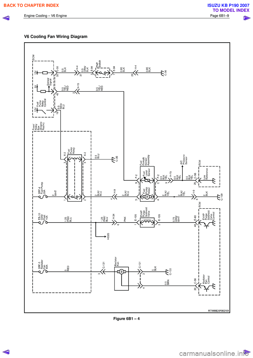
V6 Cooling Fan Wiring Diagram
Figure 6B1 – 4
BACK TO CHAPTER INDEX
TO MODEL INDEX
ISUZU KB P190 2007
Page 3150 of 6020
Engine Cooling – V6 Engine Page 6B1–15
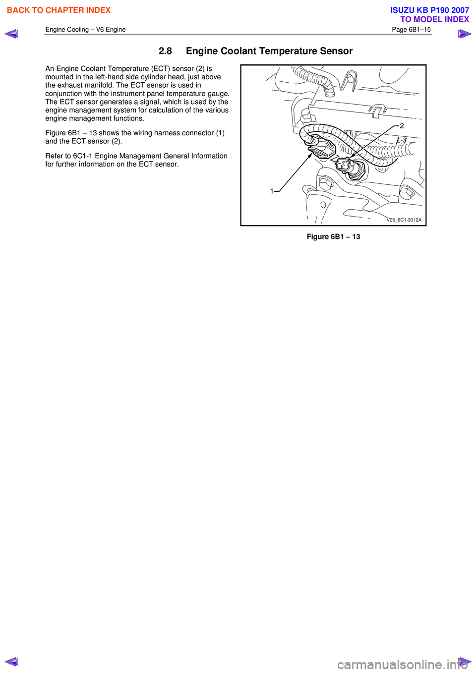
2.8 Engine Coolant Temperature Sensor
An Engine Coolant Temperature (ECT) sensor (2) is
mounted in the left-hand side cylinder head, just above
the exhaust manifold. The ECT sensor is used in
conjunction with the instrument panel temperature gauge.
The ECT sensor generates a signal, which is used by the
engine management system for calculation of the various
engine management functions.
Figure 6B1 – 13 shows the wiring harness connector (1)
and the ECT sensor (2).
Refer to 6C1-1 Engine Management General Information
for further information on the ECT sensor.
Figure 6B1 – 13
BACK TO CHAPTER INDEX
TO MODEL INDEX
ISUZU KB P190 2007
Page 3170 of 6020
Engine Cooling – V6 Engine Page 6B1–35
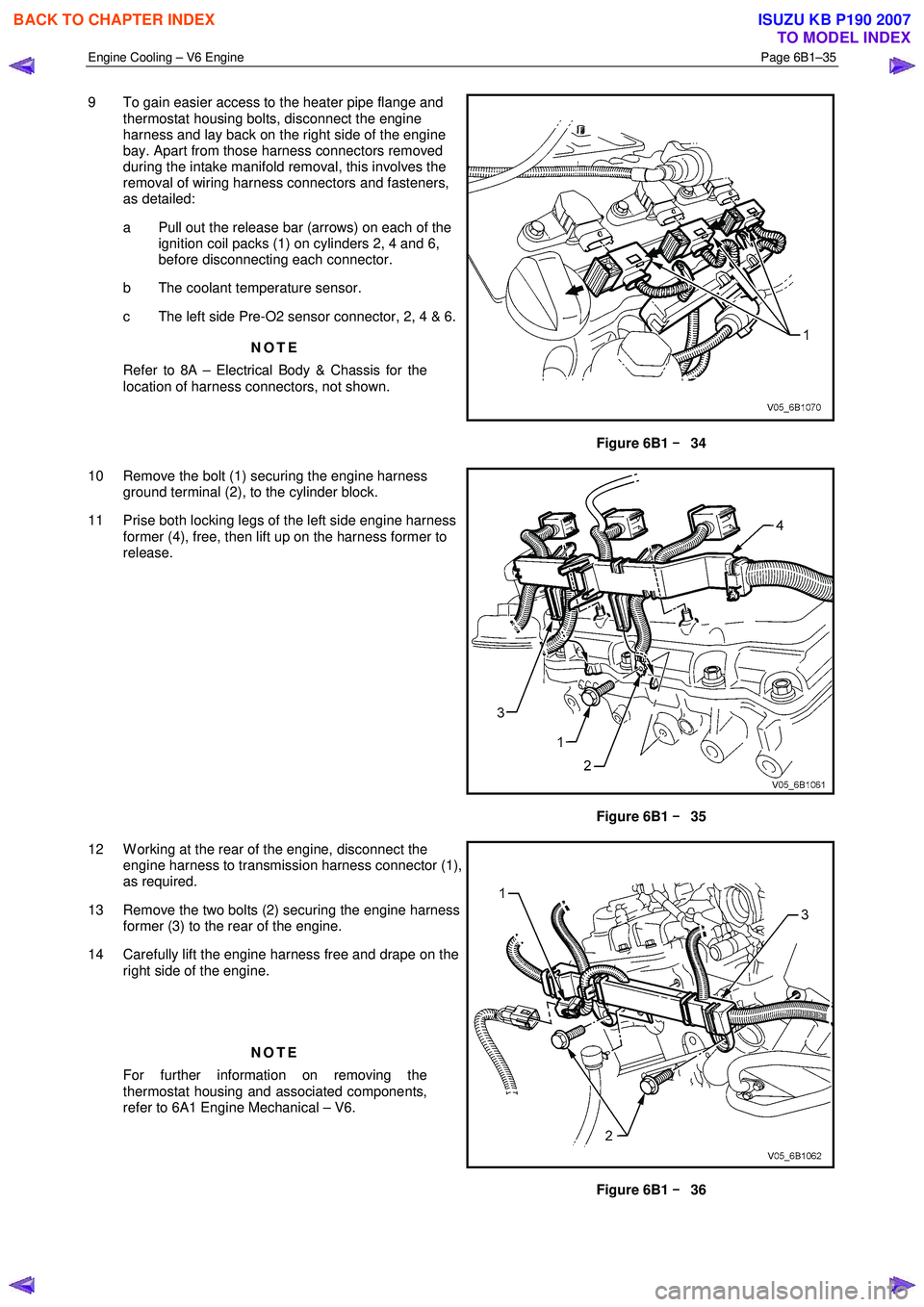
9 To gain easier access to the heater pipe flange and
thermostat housing bolts, disconnect the engine
harness and lay back on the right side of the engine
bay. Apart from those harness connectors removed
during the intake manifold removal, this involves the
removal of wiring harness connectors and fasteners,
as detailed:
a Pull out the release bar (arrows) on each of the ignition coil packs (1) on cylinders 2, 4 and 6,
before disconnecting each connector.
b The coolant temperature sensor.
c The left side Pre-O2 sensor connector, 2, 4 & 6.
NOTE
Refer to 8A – Electrical Body & Chassis for the
location of harness connectors, not shown.
Figure 6B1 –
––
–
34
10 Remove the bolt (1) securing the engine harness ground terminal (2), to the cylinder block.
11 Prise both locking legs of the left side engine harness former (4), free, then lift up on the harness former to
release.
Figure 6B1 –
––
–
35
12 W orking at the rear of the engine, disconnect the engine harness to transmission harness connector (1),
as required.
13 Remove the two bolts (2) securing the engine harness former (3) to the rear of the engine.
14 Carefully lift the engine harness free and drape on the right side of the engine.
NOTE
For further information on removing the
thermostat housing and associated components,
refer to 6A1 Engine Mechanical – V6.
Figure 6B1 –
––
–
36
BACK TO CHAPTER INDEX
TO MODEL INDEX
ISUZU KB P190 2007
Page 3173 of 6020
Engine Cooling – V6 Engine Page 6B1–38
Install
Always wear protective safety glasses when
working with spring-loaded devices. Failure to
do so could result in eye injury.
1 Install the thermostat into the housing (reverse to removal procedure).
2 Ensure that the engine block and thermostat housing mating surfaces are clean and dry.
3 Install a new gasket to the thermostat housing.
4 Install the thermostat housing to the engine block and secure with the attaching bolts (with rubber grommets installed). Tighten all bolts to the correct torque specification.
Thermostat housing to engine
block bolt torque specification ..............................10 N.m
5 Ensure that the heater pipe assembly and thermostat housing mating surfaces are clean and dry.
6 Install new O-rings to the heater pipe assembly.
7 Install heater pipe assembly to thermostat housing and secure with the attaching bolts. Tighten all bolts to the correct torque specification.
Heater pipe assembly to thermostat
housing bolt torque specification ..........................10 N.m
8 Install heater pipe assembly to right-hand cylinder head bolt. Tighten bolt to the correct torque specification. Heater pipe assembly to cylinder
head bolt torque specification ..............................35 N.m
Always wear protective safety glasses when
working with spring type hose clamps. Failure
to do so could result in eye injury.
9 Reinstall the engine wiring harness, securing the rear harness former to the rear of the engine with the two retaining bolts, tightened to the correct torque specification.
Rear engine harness former
retaining bolts torque specification .......................15 N.m
10 Reinstall the left side engine harness former to the two locating pegs, then push inward to secure.
11 Reinstall the bolt securing the engine harness ground terminal, to the left side of the cylinder block and tighten to the correct torque specification.
Engine harness ground terminal
attaching bolt torque specification ........................12 N.m
12 Reinstall each wiring harness connector to its correct location, ensuring that all security clips are installed correctly.
13 Connect the heater hoses to the heater pipe assembly.
14 Install the coolant inlet pipe. Refer to 3.12 Coolant Inlet Pipe in this Section.
15 Close the radiator drain tap on the lower LHS of the radiator and remove the piece of rubber tubing to the tap outlet.
16 Reinstall the complete intake manifold assembly. Refer to 6A1 Engine Mechanical.
17 Refill cooling system. Refer to 3.3 Draining and Filling Cooling System in this Section.
BACK TO CHAPTER INDEX
TO MODEL INDEX
ISUZU KB P190 2007
Page 3184 of 6020
Engine Cooling – V6 Engine Page 6B1–49
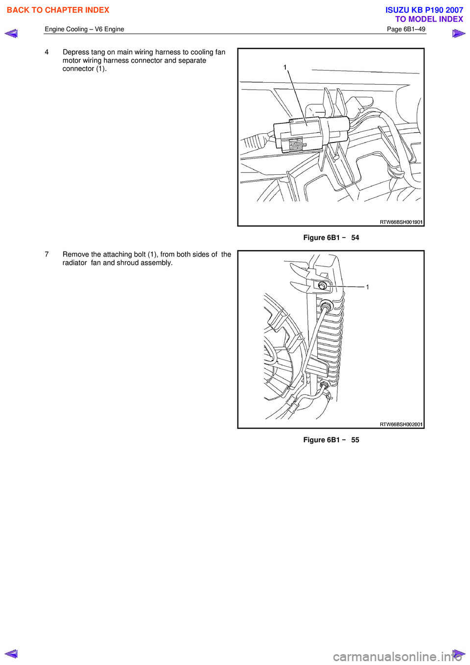
4 Depress tang on main wiring harness to cooling fan
motor wiring harness connector and separate
connector (1).
Figure 6B1 –
––
–
54
7 Remove the attaching bolt (1), from both sides of the radiator fan and shroud assembly.
Figure 6B1 –
––
–
55
BACK TO CHAPTER INDEX
TO MODEL INDEX
ISUZU KB P190 2007
Page 3186 of 6020
Engine Cooling – V6 Engine Page 6B1–51
Disassemble
1 Remove cooling fan and shroud assembly as previously described.
NOTE
Neither fan is to be separated from its fan motor.
The assembly is carefully balanced during
manufacture and duplicating this balance on
reassembly, is not possible.
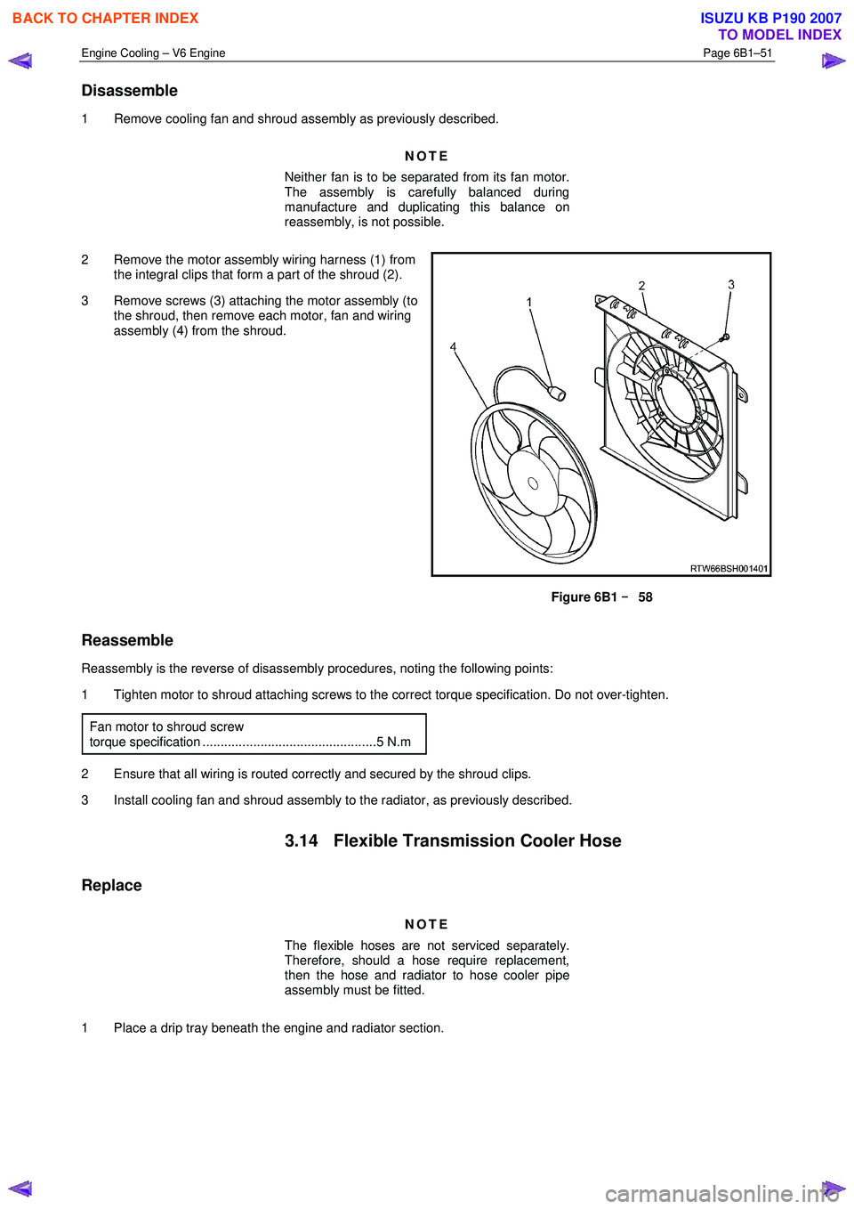
2 Remove the motor assembly wiring harness (1) from the integral clips that form a part of the shroud (2).
3 Remove screws (3) attaching the motor assembly (to the shroud, then remove each motor, fan and wiring
assembly (4) from the shroud.
Figure 6B1 –
––
–
58
Reassemble
Reassembly is the reverse of disassembly procedures, noting the following points:
1 Tighten motor to shroud attaching screws to the correct torque specification. Do not over-tighten.
Fan motor to shroud screw
torque specification ................................................5 N.m
2 Ensure that all wiring is routed correctly and secured by the shroud clips.
3 Install cooling fan and shroud assembly to the radiator, as previously described.
3.14 Flexible Transmission Cooler Hose
Replace
NOTE
The flexible hoses are not serviced separately.
Therefore, should a hose require replacement,
then the hose and radiator to hose cooler pipe
assembly must be fitted.
1 Place a drip tray beneath the engine and radiator section.
BACK TO CHAPTER INDEX
TO MODEL INDEX
ISUZU KB P190 2007
Page 3189 of 6020
Engine Cooling – V6 Engine Page 6B1–54
3.15 Radiator
Remove
Refer to 3.1 Service Notes in this Section, for
important safety items.
1 Allow engine to cool to ambient temperature (less than 50 ° C), then remove coolant filler cap.
Disconnection of the battery affects certain
vehicle electronic systems. Refer to 00
Warnings, Cautions and Notes, before
removing the ground lead.
2 Disconnect the battery ground lead. Refer to 8A – Electrical Body & Chassis.
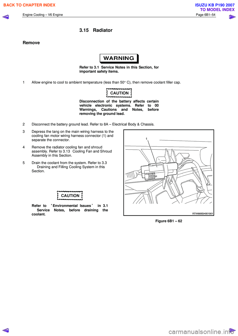
3 Depress the tang on the main wiring harness to the cooling fan motor wiring harness connector (1) and
separate the connector.
4 Remove the radiator cooling fan and shroud assembly. Refer to 3.13 Cooling Fan and Shroud
Assembly in this Section.
5 Drain the coolant from the system. Refer to 3.3 Draining and Filling Cooling System in this
Section.
Refer to ‘
‘‘
‘
Environmental Issues ’
’’
’
in 3.1
Service Notes, before draining the
coolant.
Figure 6B1 – 62
BACK TO CHAPTER INDEX
TO MODEL INDEX
ISUZU KB P190 2007