2007 ISUZU KB P190 Wiring
[x] Cancel search: WiringPage 2674 of 6020

Engine Mechanical – V6 Page 6A1–195
57 Unclip and remove the generator wiring harness
connector (1), Remove battery connection attaching
nut (4), and remove the battery harness cable (2)
from the connection stud.
Figure 6A1 – 345
58 Remove the generator attaching bolts (1, 2, and 4) three places, then remove the generator (3) from the
mounting bracket.
Figure 6A1 – 346
59 Remove the idler pulley attaching bolt and remove the idler pulley (1).
60 Remove the generator bracket attaching bolts, five places, and remove the generator mounting bracket
(2).
Figure 6A1 – 347
BACK TO CHAPTER INDEX
TO MODEL INDEX
ISUZU KB P190 2007
Page 2676 of 6020
Engine Mechanical – V6 Page 6A1–197
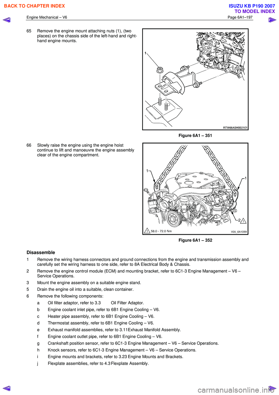
65 Remove the engine mount attaching nuts (1), (two
places) on the chassis side of the left-hand and right-
hand engine mounts.
Figure 6A1 – 351
66 Slowly raise the engine using the engine hoist continue to lift and manoeuvre the engine assembly
clear of the engine compartment.
Figure 6A1 – 352
Disassemble
1 Remove the wiring harness connectors and ground connections from the engine and transmission assembly and carefully set the wiring harness to one side, refer to 8A Electrical Body & Chassis.
2 Remove the engine control module (ECM) and mounting bracket, refer to 6C1-3 Engine Management – V6 – Service Operations.
3 Mount the engine assembly on a suitable engine stand.
5 Drain the engine oil into a suitable, clean container.
6 Remove the following components: a Oil filter adaptor, refer to 3.3 Oil Filter Adaptor.
b Engine coolant inlet pipe, refer to 6B1 Engine Cooling – V6.
c Heater pipe assembly, refer to 6B1 Engine Cooling – V6.
d Thermostat assembly, refer to 6B1 Engine Cooling – V6.
e Exhaust manifold assemblies, refer to 3.11Exhaust Manifold Assembly.
f Engine coolant outlet pipe, refer to 6B1 Engine Cooling – V6.
g Crankshaft position sensor, refer to 6C1-3 Engine Management – V6 – Service Operations.
h Knock sensors, refer to 6C1-3 Engine Management – V6 – Service Operations.
i Engine mounts and brackets, refer to 3.23 Engine Mounts and Brackets.
j Flexplate assemblies, refer to 4.3 Flexplate Assembly.
BACK TO CHAPTER INDEX
TO MODEL INDEX
ISUZU KB P190 2007
Page 2771 of 6020
Engine Mechanical – V6 Page 6A1–292
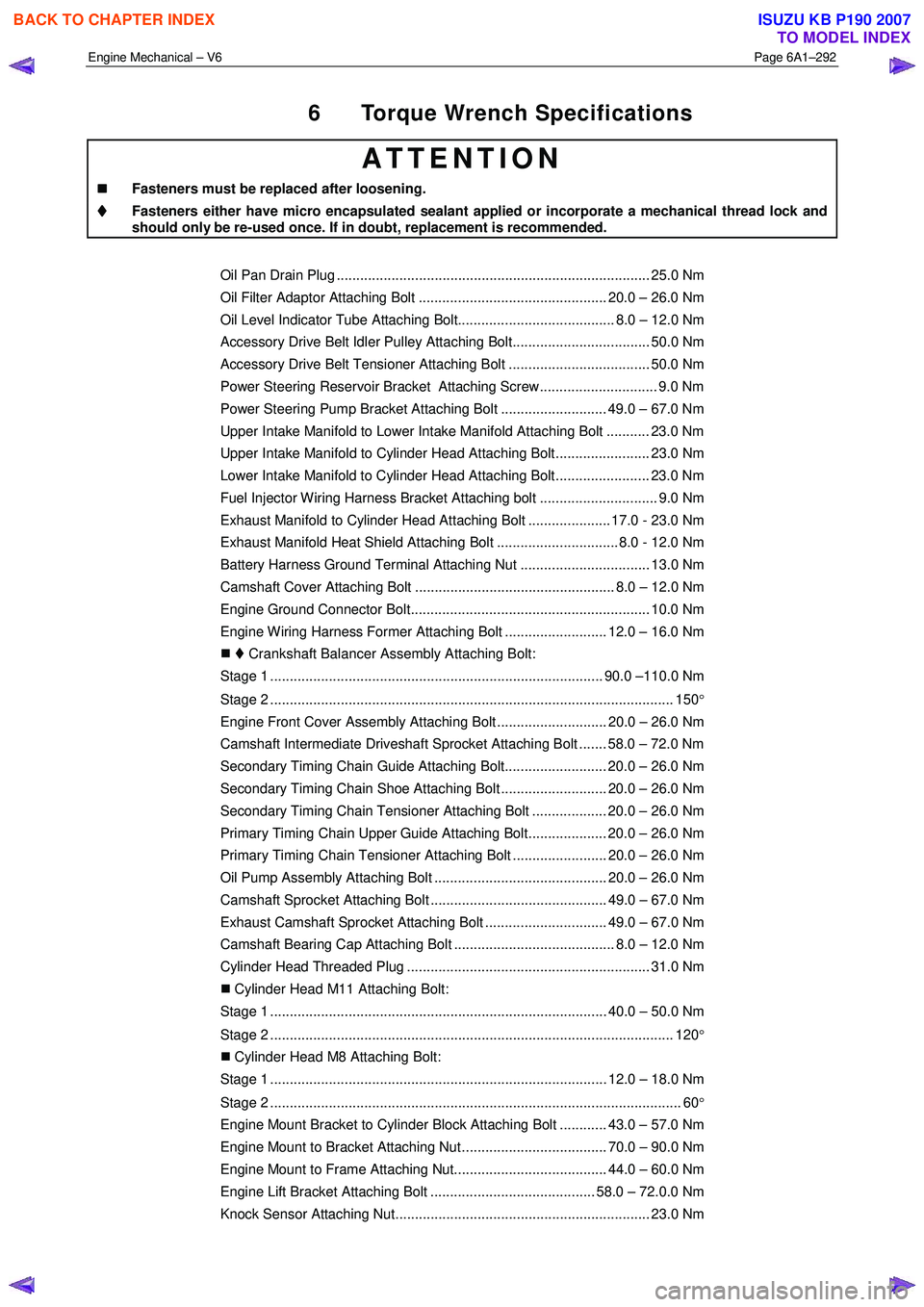
6 Torque Wrench Specifications
ATTENTION
�„
�„�„
�„
Fasteners must be replaced after loosening.
Fasteners either have micro encapsulated sealant applied or incorporate a mechanical thread lock and
should only be re-used once. If in doubt, replacement is recommended.
Oil Pan Drain Plug ................................................................................ 25.0 Nm
Oil Filter Adaptor Attaching Bolt ................................................ 20.0 – 26.0 Nm
Oil Level Indicator Tube Attaching Bolt........................................ 8.0 – 12.0 Nm
Accessory Drive Belt Idler Pulley Attaching Bolt................................... 50.0 Nm
Accessory Drive Belt Tensioner Attaching Bolt .................................... 50.0 Nm
Power Steering Reservoir Bracket Attaching Screw.............................. 9.0 Nm
Power Steering Pump Bracket Attaching Bolt ........................... 49.0 – 67.0 Nm
Upper Intake Manifold to Lower Intake Manifold Attaching Bolt ........... 23.0 Nm
Upper Intake Manifold to Cylinder Head Attaching Bolt........................ 23.0 Nm
Lower Intake Manifold to Cylinder Head Attaching Bolt........................ 23.0 Nm
Fuel Injector Wiring Harness Bracket Attaching bolt .............................. 9.0 Nm
Exhaust Manifold to Cylinder Head Attaching Bolt ..................... 17.0 - 23.0 Nm
Exhaust Manifold Heat Shield Attaching Bolt ............................... 8.0 - 12.0 Nm
Battery Harness Ground Terminal Attaching Nut ................................. 13.0 Nm
Camshaft Cover Attaching Bolt ................................................... 8.0 – 12.0 Nm
Engine Ground Connector Bolt............................................................. 10.0 Nm
Engine Wiring Harness Former Attaching Bolt .......................... 12.0 – 16.0 Nm
�„ Crankshaft Balancer Assembly Attaching Bolt:
Stage 1 ..................................................................................... 90.0 –110.0 Nm
Stage 2 ....................................................................................................... 150 °
Engine Front Cover Assembly Attaching Bolt ............................ 20.0 – 26.0 Nm
Camshaft Intermediate Driveshaft Sprocket Attaching Bolt ....... 58.0 – 72.0 Nm
Secondary Timing Chain Guide Attaching Bolt.......................... 20.0 – 26.0 Nm
Secondary Timing Chain Shoe Attaching Bolt ........................... 20.0 – 26.0 Nm
Secondary Timing Chain Tensioner Attaching Bolt ................... 20.0 – 26.0 Nm
Primary Timing Chain Upper Guide Attaching Bolt.................... 20.0 – 26.0 Nm
Primary Timing Chain Tensioner Attaching Bolt ........................ 20.0 – 26.0 Nm
Oil Pump Assembly Attaching Bolt ............................................ 20.0 – 26.0 Nm
Camshaft Sprocket Attaching Bolt ............................................. 49.0 – 67.0 Nm
Exhaust Camshaft Sprocket Attaching Bolt ............................... 49.0 – 67.0 Nm
Camshaft Bearing Cap Attaching Bolt ......................................... 8.0 – 12.0 Nm
Cylinder Head Threaded Plug .............................................................. 31.0 Nm
�„ Cylinder Head M11 Attaching Bolt:
Stage 1 ...................................................................................... 40.0 – 50.0 Nm
Stage 2 ....................................................................................................... 120 °
�„ Cylinder Head M8 Attaching Bolt:
Stage 1 ...................................................................................... 12.0 – 18.0 Nm
Stage 2 ......................................................................................................... 60 °
Engine Mount Bracket to Cylinder Block Attaching Bolt ............ 43.0 – 57.0 Nm
Engine Mount to Bracket Attaching Nut ..................................... 70.0 – 90.0 Nm
Engine Mount to Frame Attaching Nut....................................... 44.0 – 60.0 Nm
Engine Lift Bracket Attaching Bolt .......................................... 58.0 – 72.0.0 Nm
Knock Sensor Attaching Nut................................................................. 23.0 Nm
BACK TO CHAPTER INDEX
TO MODEL INDEX
ISUZU KB P190 2007
Page 2788 of 6020
Engine Mechanical – V6 Page 6A1–11
Page 6A1–11
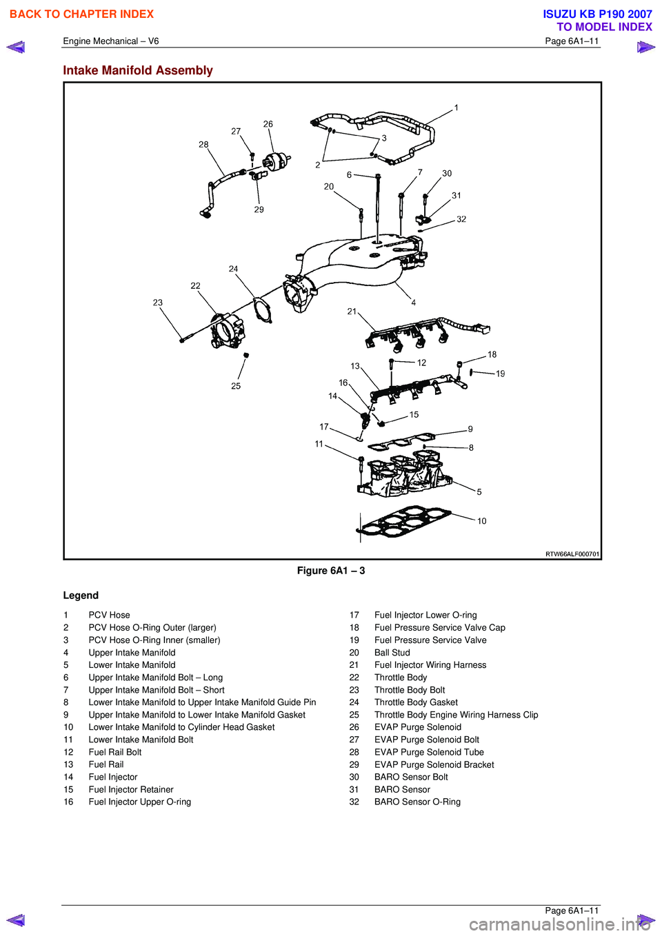
Intake Manifold Assembly
Figure 6A1 – 3
Legend
1 PCV Hose
2 PCV Hose O-Ring Outer (larger)
3 PCV Hose O-Ring Inner (smaller)
4 Upper Intake Manifold
5 Lower Intake Manifold
6 Upper Intake Manifold Bolt – Long
7 Upper Intake Manifold Bolt – Short
8 Lower Intake Manifold to Upper Intake Manifold Guide Pin
9 Upper Intake Manifold to Lower Intake Manifold Gasket
10 Lower Intake Manifold to Cylinder Head Gasket
11 Lower Intake Manifold Bolt
12 Fuel Rail Bolt
13 Fuel Rail
14 Fuel Injector
15 Fuel Injector Retainer
16 Fuel Injector Upper O-ring 17 Fuel Injector Lower O-ring
18 Fuel Pressure Service Valve Cap
19 Fuel Pressure Service Valve
20 Ball Stud
21 Fuel Injector Wiring Harness
22 Throttle Body
23 Throttle Body Bolt
24 Throttle Body Gasket
25 Throttle Body Engine Wiring Harness Clip
26 EVAP Purge Solenoid
27 EVAP Purge Solenoid Bolt
28 EVAP Purge Solenoid Tube
29 EVAP Purge Solenoid Bracket
30 BARO Sensor Bolt
31 BARO Sensor
32 BARO Sensor O-Ring
BACK TO CHAPTER INDEX
TO MODEL INDEX
ISUZU KB P190 2007
Page 2847 of 6020
Engine Mechanical – V6 Page 6A1–70
Page 6A1–70
3.3 Oil Filter Adaptor
Remove
Disconnection of the battery affects
certain vehicle electronic systems, refer to
1.1 WARNING, CAUTION and NOTES before
disconnecting the battery.
1 Disconnect the battery negative terminal.
2 Disconnect the wiring harness connecto r from the oil pressure sender.
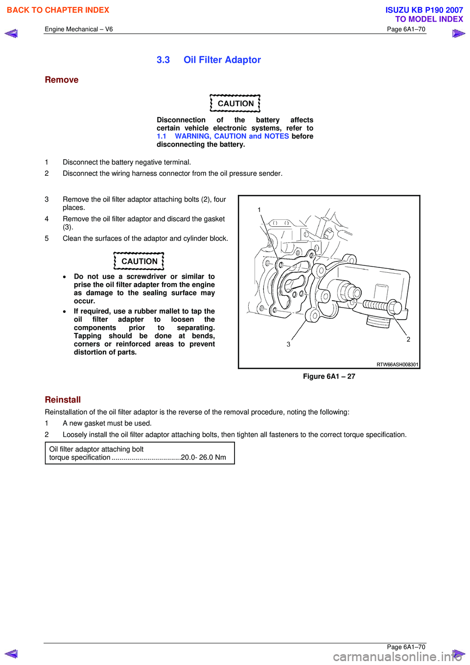
3 Remove the oil filter adaptor attaching bolts (2), four
places.
4 Remove the oil filter adaptor and discard the gasket (3).
5 Clean the surfaces of t he adaptor and cylinder block.
• Do not use a screwdriver or similar to
prise the oil filter adapter from the engine
as damage to the sealing surface may
occur.
• If required, use a rubber mallet to tap the
oil filter adapter to loosen the
components prior to separating.
Tapping should be done at bends,
corners or reinforced areas to prevent
distortion of parts.
Figure 6A1 – 27
Reinstall
Reinstallation of the oil filter adaptor is the reverse of the remo val procedure, noting the following:
1 A new gasket must be used.
2 Loosely install the oil filter adaptor attaching bolts, then tighten all fast eners to the correct torque specification.
Oil filter adaptor attaching bolt
torque specificatio n ...................................20.0- 26.0 Nm
BACK TO CHAPTER INDEX
TO MODEL INDEX
ISUZU KB P190 2007
Page 2848 of 6020
Engine Mechanical – V6 Page 6A1–71
Page 6A1–71
3.4 Oil Level Indicator Tube
Remove
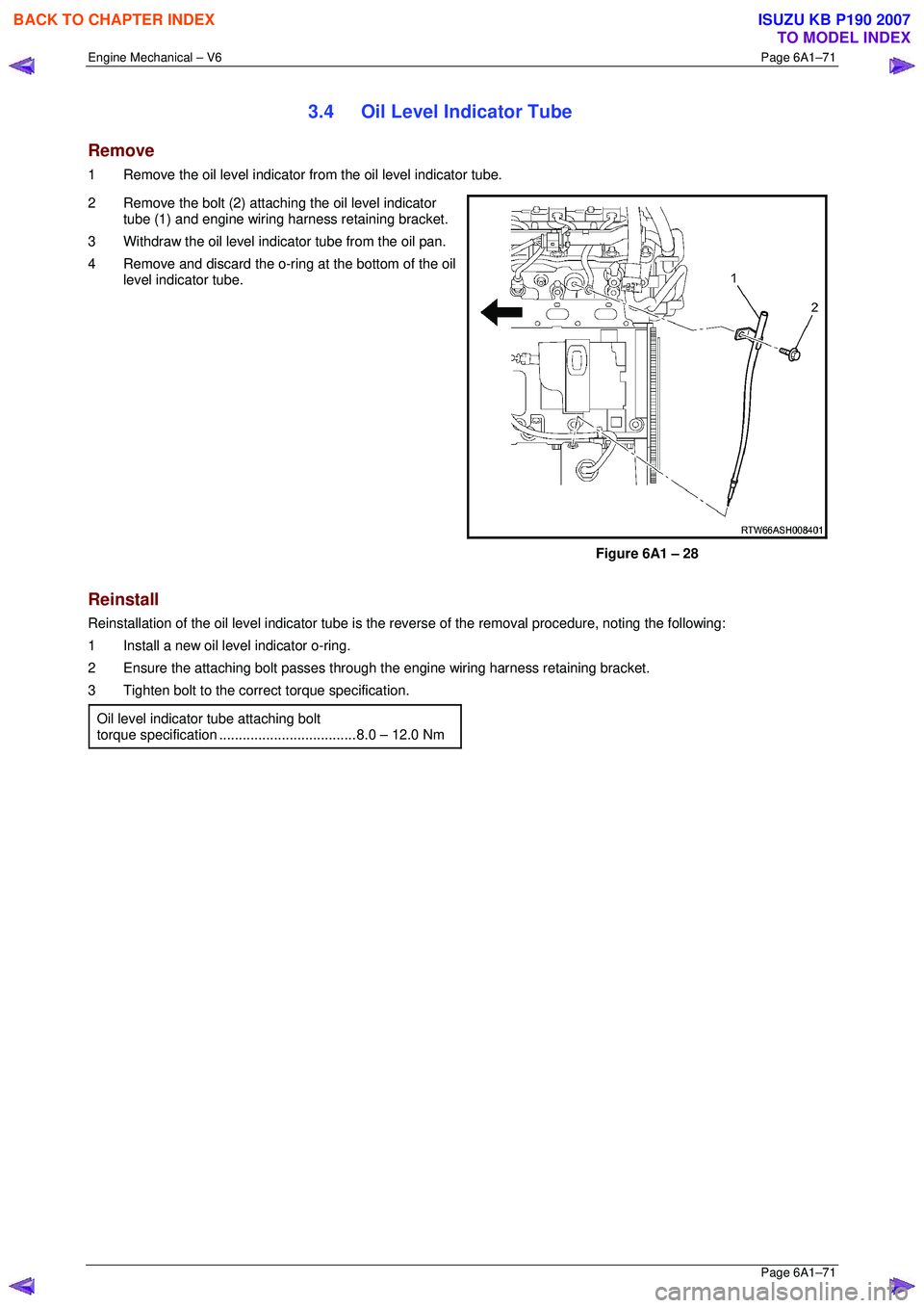
1 Remove the oil level indicator from the oil level indicator tube.
2 Remove the bolt (2) attaching the oil level indicator tube (1) and engine wiring harness retaining bracket.
3 Withdraw the oil level indi cator tube from the oil pan.
4 Remove and discard the o-ring at the bottom of the oil level indicator tube.
Figure 6A1 – 28
Reinstall
Reinstallation of the oil level indicator tube is the reverse of the removal procedure, noting the following:
1 Install a new oil level indicator o-ring.
2 Ensure the attaching bolt passes through the engine wiring harness retaining bracket.
3 Tighten bolt to the correct torque specification.
Oil level indicator tube attaching bolt
torque specificatio n ................................... 8. 0 – 12.0 Nm
BACK TO CHAPTER INDEX
TO MODEL INDEX
ISUZU KB P190 2007
Page 2855 of 6020
Engine Mechanical – V6 Page 6A1–78
Page 6A1–78
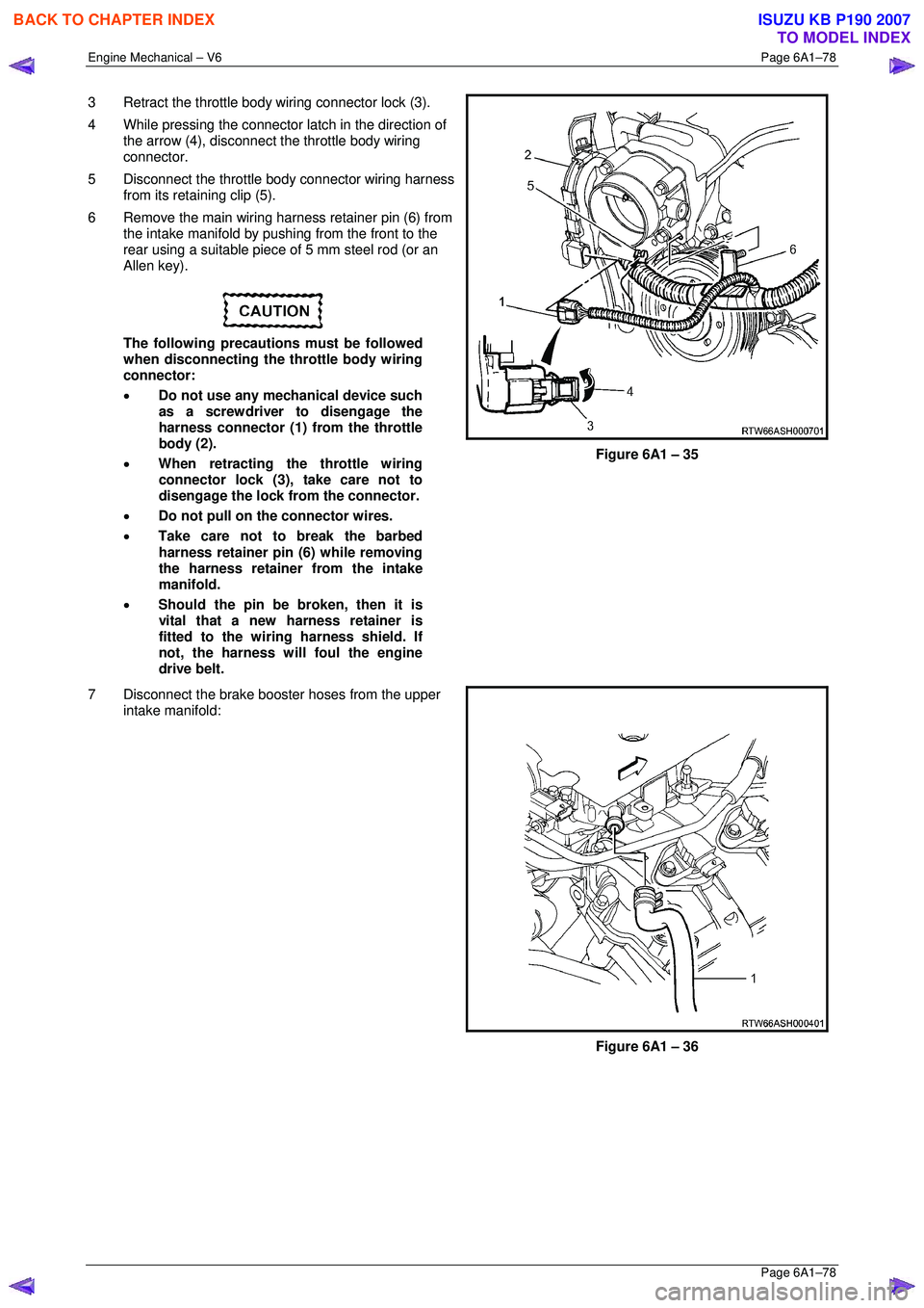
3 Retract the throttle body wiring connector lock (3).
4 While pressing the connector latch in the direction of
the arrow (4), disconnect the throttle body wiring
connector.
5 Disconnect the throttle body connector wiring harness from its retaining clip (5).
6 Remove the main wiring harness retainer pin (6) from the intake manifold by pushing from the front to the
rear using a suitable piece of 5 mm steel rod (or an
Allen key).
The following precautions must be followed
when disconnecting the throttle body wiring
connector:
• Do not use any mechanical device such
as a screwdriver to disengage the
harness connector (1) from the throttle
body (2).
• When retracting the throttle wiring
connector lock (3), take care not to
disengage the lock from the connector.
• Do not pull on the connector wires.
• Take care not to break the barbed
harness retainer pin (6) while removing
the harness retainer from the intake
manifold.
• Should the pin be broken, then it is
vital that a new harness retainer is
fitted to the wiring harness shield. If
not, the harness will foul the engine
drive belt.
Figure 6A1 – 35
7 Disconnect the brake booster hoses from the upper intake manifold:
Figure 6A1 – 36
BACK TO CHAPTER INDEX
TO MODEL INDEX
ISUZU KB P190 2007
Page 2856 of 6020
Engine Mechanical – V6 Page 6A1–79
Page 6A1–79
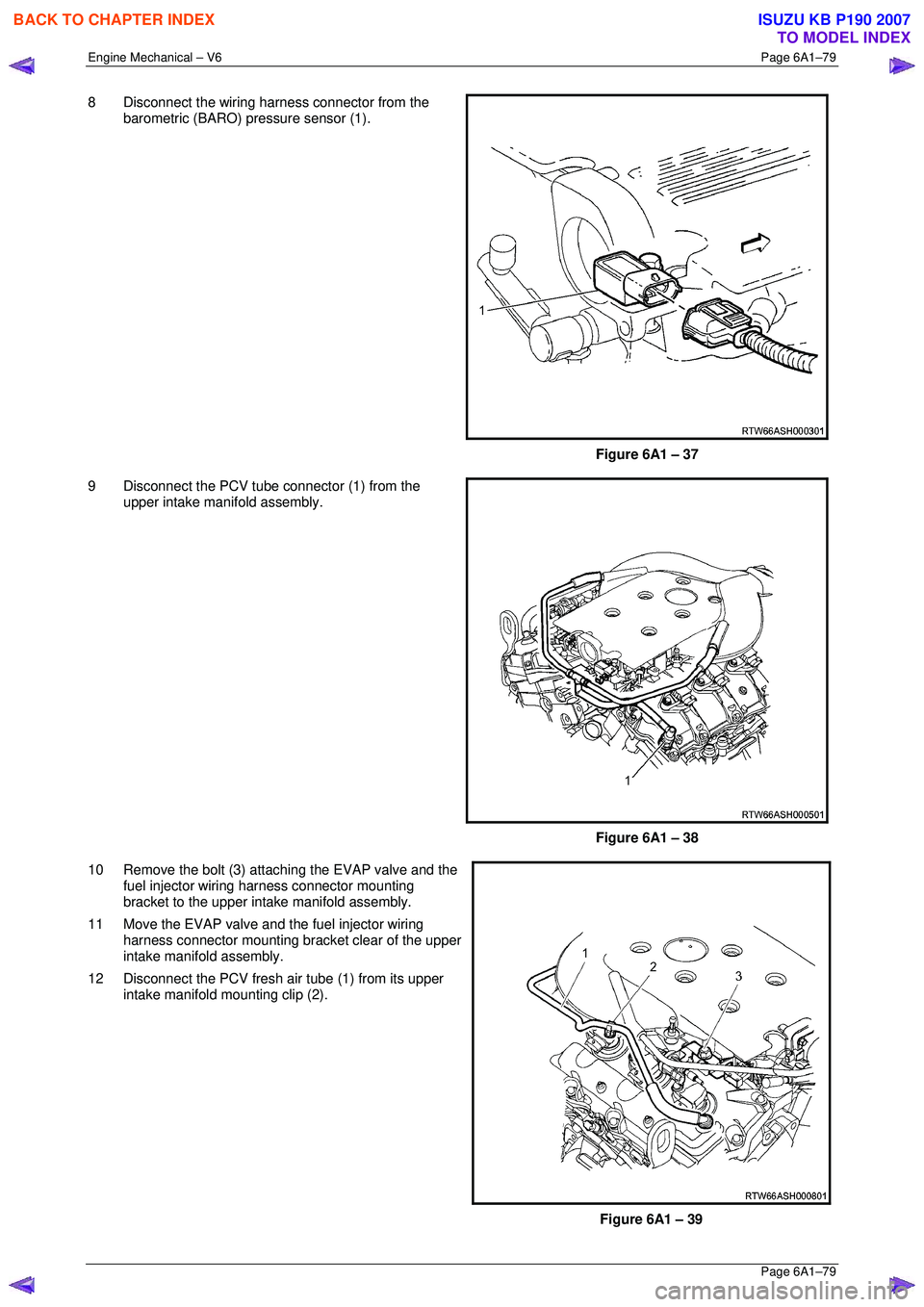
8 Disconnect the wiring harness connector from the
barometric (BARO) pressure sensor (1).
Figure 6A1 – 37
9 Disconnect the PCV tube connector (1) from the upper intake manifold assembly.
Figure 6A1 – 38
10 Remove the bolt (3) attaching the EVAP valve and the fuel injector wiring harness connector mounting
bracket to the upper inta ke manifold assembly.
11 Move the EVAP valve and the fuel injector wiring harness connector mounting br acket clear of the upper
intake manifold assembly.
12 Disconnect the PCV fresh air tube (1) from its upper intake manifold mounting clip (2).
Figure 6A1 – 39
BACK TO CHAPTER INDEX
TO MODEL INDEX
ISUZU KB P190 2007