2007 ISUZU KB P190 Wiring
[x] Cancel search: WiringPage 5749 of 6020
RESTRAINT CONTROL SYSTEM 9A1-67
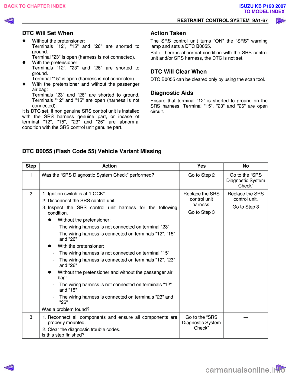
Step Action Yes No
1 W as the “SRS Diagnostic System Check” performed? Go to Step 2 Go to the “SRS
Diagnostic System Check”
2 1. Ignition switch is at “LOCK”.
2. Disconnect the SRS control unit.
3. Inspect the SRS control unit harness for the following condition.
�z W ithout the pretensioner:
- The wiring harness is not connected on terminal "23"
- The wiring harness is connected on terminals "12", "15" and "26"
�z W ith the pretensioner:
- The wiring harness is not connected on terminal "15"
- The wiring harness is connected on terminals "12", "23" and "26"
�z W ithout the pretensioner and without the passenger air
bag:
- The wiring harness is not connected on terminals "12" and "15"
- The wiring harness is connected on terminals "23" and "26"
W as a problem found? Replace the SRS
control unit harness.
Go to Step 3 Replace the SRS
control unit.
Go to Step 3
3 1. Reconnect all components and ensure all components are
properly mounted.
2. Clear the diagnostic trouble codes.
Is this step finished? Go to the “SRS
Diagnostic System Check” ―
DTC Will Set When
�z W ithout the pretensioner:
Terminals "12", "15" and "26" are shorted to
ground.
Terminal "23" is open (harness is not connected).
�z W ith the pretensioner:
Terminals "12", "23" and "26" are shorted to
ground.
Terminal "15" is open (harness is not connected).
�z W ith the pretensioner and without the passenge
r
air bag:
Terminals "23" and "26" are shorted to ground.
Terminals "12" and "15" are open (harness is not
connected).
It is DTC set, if non genuine SRS control unit is installed
with the SRS harness genuine part, or incase o
f
terminal "12", "15", "23" and "26" are abnormal
condition with the SRS control unit genuine part.
Action Taken
The SRS control unit turns “ON" the “SRS" warning
lamp and sets a DTC B0055.
But if there is abnormal condition with the SRS control
unit and/or SRS harness, the DTC is not set.
DTC Will Clear When
DTC B0055 can be cleared only by using the scan tool.
Diagnostic Aids
Ensure that terminal "12" is shorted to ground on the
SRS harness. Terminal "15", "23" and "26" are open
circuit.
DTC B0055 (Flash Code 55) Vehicle Variant Missing
BACK TO CHAPTER INDEX TO MODEL INDEX
ISUZU KB P190 2007
Page 5900 of 6020
11A-2 IMMOBILIZER SYSTEM (C24SE, 4JA1-T)
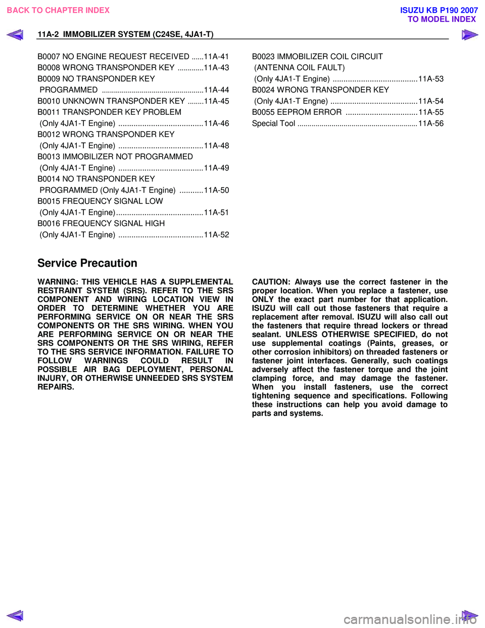
B0007 NO ENGINE REQUEST RECEIVED ......11A-41
B0008 W RONG TRANSPONDER KEY .............11A-43
B0009 NO TRANSPONDER KEY
PROGRAMMED ................................................... 11A-44
B0010 UNKNOW N TRANSPONDER KEY ........11A-45
B0011 TRANSPONDER KEY PROBLEM
(Only 4JA1-T Engine) .......................................11A-46
B0012 W RONG TRANSPONDER KEY
(Only 4JA1-T Engine) .......................................11A-48
B0013 IMMOBILIZER NOT PROGRAMMED
(Only 4JA1-T Engine) .......................................11A-49
B0014 NO TRANSPONDER KEY
PROGRAMMED (Only 4JA1-T Engine) ...........11A-50
B0015 FREQUENCY SIGNAL LOW
(Only 4JA1-T Engine) ........................................11A-51
B0016 FREQUENCY SIGNAL HIGH
(Only 4JA1-T Engine) .......................................11A-52
B0023 IMMOBILIZER COIL CIRCUIT
(ANTENNA COIL FAULT)
(Only 4JA1-T Engine) ....................................... 11A-53
B0024 W RONG TRANSPONDER KEY
(Only 4JA1-T Engne) ........................................ 11A-54
B0055 EEPROM ERROR ................................. 11A-55
Special Tool ............................................................ 11A-56
Service Precaution
WARNING: THIS VEHICLE HAS A SUPPLEMENTAL
RESTRAINT SYSTEM (SRS). REFER TO THE SRS
COMPONENT AND WIRING LOCATION VIEW IN
ORDER TO DETERMINE WHETHER YOU ARE
PERFORMING SERVICE ON OR NEAR THE SRS
COMPONENTS OR THE SRS WIRING. WHEN YOU
ARE PERFORMING SERVICE ON OR NEAR THE
SRS COMPONENTS OR THE SRS WIRING, REFER
TO THE SRS SERVICE INFORMATION. FAILURE TO
FOLLOW WARNINGS COULD RESULT IN
POSSIBLE AIR BAG DEPLOYMENT, PERSONAL
INJURY, OR OTHERWISE UNNEEDED SRS SYSTEM
REPAIRS.
CAUTION: Always use the correct fastener in the
proper location. When you replace a fastener, use
ONLY the exact part number for that application.
ISUZU will call out those fasteners that require a
replacement after removal. ISUZU will also call out
the fasteners that require thread lockers or thread
sealant. UNLESS OTHERWISE SPECIFIED, do not
use supplemental coatings (Paints, greases, o
r
other corrosion inhibitors) on threaded fasteners or
fastener joint interfaces. Generally, such coatings
adversely affect the fastener torque and the joint
clamping force, and may damage the fastener.
When you install fasteners, use the correct
tightening sequence and specifications. Following
these instructions can help you avoid damage to
parts and systems.
BACK TO CHAPTER INDEX
TO MODEL INDEX
ISUZU KB P190 2007
Page 5956 of 6020
11B-2 ANTITHEFT SYSTEM
Service Precaution
WARNING: THIS VEHICLE HAS A SUPPLEMENTAL
RESTRAINT SYSTEM (SRS). REFER TO THE SRS
COMPONENT AND WIRING LOCATION VIEW IN
ORDER TO DETERMINE WHETHER YOU ARE
PERFORMING SERVICE ON OR NEAR THE SRS
COMPONENTS OR THE SRS WIRING. WHEN YOU
ARE PERFORMING SERVICE ON OR NEAR THE
SRS COMPONENTS OR THE SRS WIRING, REFER
TO THE SRS SERVICE INFORMATION. FAILURE TO
FOLLOW WARNINGS COULD RESULT IN
POSSIBLE AIR BAG DEPLOYMENT, PERSONAL
INJURY, OR OTHERWISE UNNEEDED SRS SYSTEM
REPAIRS.
CAUTION: Always use the correct fastener in the
proper location. When you replace a fastener, use
ONLY the exact part number for that application.
ISUZU will call out those fasteners that require a
replacement after removal. ISUZU will also call out
the fasteners that require thread lockers or thread
sealant. UNLESS OTHERWISE SPECIFIED, do not
use supplemental coatings (Paints, greases, or
other corrosion inhibitors) on threaded fasteners or
fastener joint interfaces. Generally, such coatings
adversely affect the fastener torque and the joint
clamping force, and may damage the fastener.
When you install fasteners, use the correct
tightening sequence and specifications. Following
these instructions can help you avoid damage to
parts and systems.
General Description
The Antitheft system consists of the four major
components which are Antitheft Control Unit (ACU),
Antitheft horn, key (remote key), and scan tool (Tech-2).
This system can be activated by a correctly
programmed key (remote key) and starter switch is set
to OFF.
This system can be deactivated by a correctly
programmed key (remote key) connected with a
correctly programmed ACU and a correctly
programmed lCU.
W hen the vehicle doors, and engine hood are locked,
the antitheft alarm system is designed to protect your
vehicle and valuables from theft.
Any attempt to forcibly open any door, the engine hood
without using the vehicle key (or remote control) will
cause the hazard lights to flash on and off and the horn
to sound intermittently. This will continue for 30 seconds
(Hazard lamp flash; For 5 minutes) before the system
automatically shuts itself off.
Please operate the door either the key lock or remote
key after closing all doors to arm the alarm system.
Miss waning will be detected when the passenger door
is opened with locked condition and then this door is
closed.
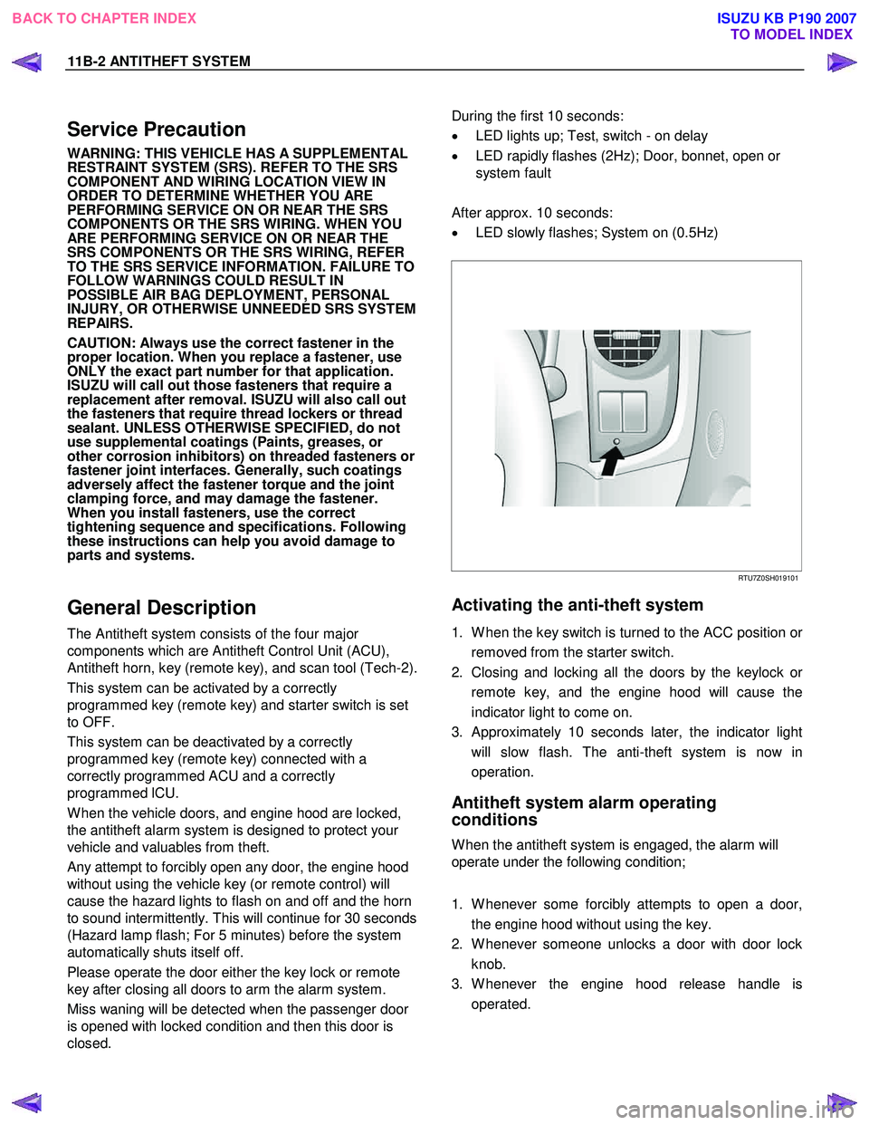
During the first 10 seconds:
• LED lights up; Test, switch - on delay
• LED rapidly flashes (2Hz); Door, bonnet, open or
system fault
After approx. 10 seconds:
• LED slowly flashes; System on (0.5Hz)
RTU7Z0SH019101
Activating the anti-theft system
1. W hen the key switch is turned to the ACC position or
removed from the starter switch.
2. Closing and locking all the doors by the keylock o
r
remote key, and the engine hood will cause the
indicator light to come on.
3. Approximately 10 seconds later, the indicator light will slow flash. The anti-theft system is now in
operation.
Antitheft system alarm operating
conditions
W hen the antitheft system is engaged, the alarm will
operate under the following condition;
1. W henever some forcibly attempts to open a door, the engine hood without using the key.
2. W henever someone unlocks a door with door lock knob.
3. W henever the engine hood release handle is operated.
BACK TO CHAPTER INDEX TO MODEL INDEX
ISUZU KB P190 2007
Page 5959 of 6020
ANTITHEFT SYSTEM 11B-5
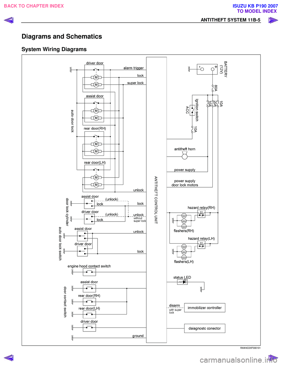
Diagrams and Schematics
System Wiring Diagrams
RAW 4C0XF000101
BACK TO CHAPTER INDEXTO MODEL INDEX
ISUZU KB P190 2007
Page 5990 of 6020
11B-36 ANTITHEFT SYSTEM
Diagnosis
Diagnostic procedure
• Once the cause of DTC is repaired or gone,
engine can be operated normally, and present
DTC becomes history code.
• History code is canceled by no repeat failure on 25
consequence ignition key on afterward.
• History code cannot be canceled by batter
y
connector disconnected.
Clearing Diagnostic Trouble Codes
IMPORTANT: Do not clear DTCs unless directed to do
so by the service information provided for each
diagnostic procedure. W hen DTCs are cleared, the
Failure Record data which may help diagnose an
intermittent fault will also be erased from memory.
Verifying Vehicle Repair
Verification of vehicle repair will be more
comprehensive for vehicles with immobilizer system
diagnostic. Following a repair, the technician should
perform the following steps:
1. Review and record the Fail Records for the DTC which has been diagnosed.
2. Clear DTC (s).
3. Operate the vehicle within conditions noted in the Fail Records.
4. Monitor the DTC status information for the DTC which has been diagnosed until the diagnostic test
associated with that DTC runs.
Following these steps are very important in verifying
repairs on immobilizer systems. Failure to follow these
steps could result in unnecessary repairs.
Diagnostic Aids
An intermittent may be caused by the following:
• Poor connections.
• Miss routed harness.
• Rubbed through wire insulation.
• Broken wire inside the insulation.
Check for the following conditions:
• Poor connection at ACU-Inspect harness
connectors for backed out terminals, imprope
r
mating, broken locks, improperly formed or
damaged terminals, and poor terminal to wire
connection.
• Damaged harness-Inspect the wiring harness fo
r
damage.
If the harness appears to be OK, observe the data
display on the Tech2 while moving connectors and
wiring harnesses related to the switch or actuator.
A change in the display will indicate the location of
the fault.
If DTC cannot be duplicated, the information included in the Failure Records data can be useful
in determined vehicle mileage since the DTC was
last set.
If it is determined that the DTC occurs intermittently, performing the DTC Diagnostic
Chart may isolate the cause of the fault.
NOTE: Breakage of antitheft fuse does not operate
antitheft system. Check LED lamp flashes at this time.
Check the Electro-Magnetic Interference (EMI)
• Location of vehicle check
Move the vehicle to a new location and perform
the check again.
• Non-OEM Parts.
Switch is “OFF” or remove the Non-OEM parts and
perform the check again.
• Other
Remove the accessory and another key from key.
Check the other items.
• Battery voltage is low.
• Antitheft programming functions.
Must be programmed antitheft system.
• Registration for security code, antitheft control unit
parts number.
• Key switch operation.
Antitheft system may detect a history DTC by the
timing of ON-OFF of a key switch.
• Active the antitheft system.
• Keyless entry system is malfunction.
• Immobilizer system is malfunction.
Check the operation
Check the operation "Lock / unlock" by using transmitter
(key) on the vehicle.
BACK TO CHAPTER INDEX TO MODEL INDEX
ISUZU KB P190 2007