Page 2554 of 6020

Engine Mechanical – V6 Page 6A1–75
CAUTION
Tighten the intake manifold bolts in a circular
pattern starting at the centre bolt and moving
outward.
4 Ensure that all fasteners are tightened to the correct torque specification. Upper intake manifold to lower intake
manifold attaching bolt torque specification .......23.0 Nm
Upper intake manifold to cylinder
head attaching bolt torque specification .............23.0 Nm
Lower intake manifold to cylinder
head attaching bolt torque specification .............23.0 Nm
Fuel injector wiring harness bracket
attaching bolt torque specification ........................9.0 Nm
Incorrect wiring connector installation may
cause component malfunction or component
damage.
5 Ensure all wiring connectors are fully engaged and if applicable, locked in place.
6 Ensure all wiring harnesses are correctly routed and attached securely in their retaining clips.
7 Ensure that all hoses and pipes are routed correctly and that any retaining clips are correctly installed.
8 After installation pull on any quick connect fittings to check that each is correctly installed.
9 Start and run the engine to check for correct operation.
3.11 Exhaust Manifold Assembly
Remove
Allow the engine to cool before commencing.
Disconnection of the battery affects certain
vehicle electronic systems, refer to 1.1
WARNING, CAUTION and NOTES before
disconnecting the battery.
1 Disconnect the battery negative terminal.
BACK TO CHAPTER INDEX
TO MODEL INDEX
ISUZU KB P190 2007
Page 2555 of 6020

Engine Mechanical – V6 Page 6A1–76
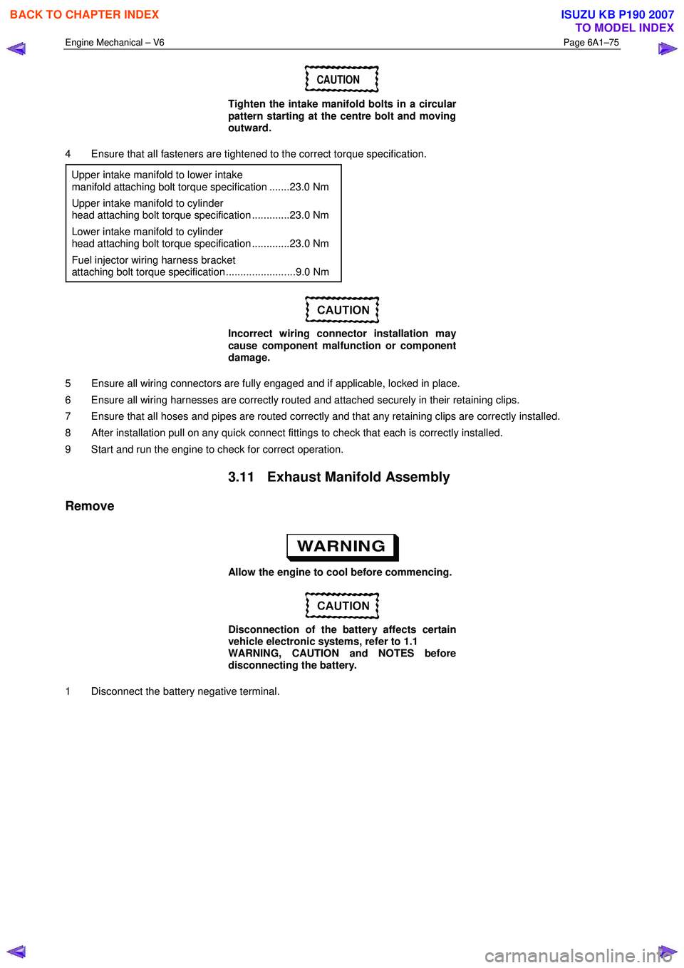
2 Remove the oxygen sensor harness connector (1)
from the retaining bracket.
3 Disconnect the oxygen sensor wiring harness connector from the engine wiring harness connector
(2).
4 Unclip the oxygen sensor wiring harness retaining clip and move aside.
5 For the left-hand side: Remove the oil level indicator tube.
6 Raise the front of the vehicle and place on stands, refer to 0A General Information.
7 W orking from under the vehicle, remove the two exhaust manifold to exhaust pipe flange nuts, refer to
6F Exhaust System - V6 - V6.
Figure 6A1 – 56
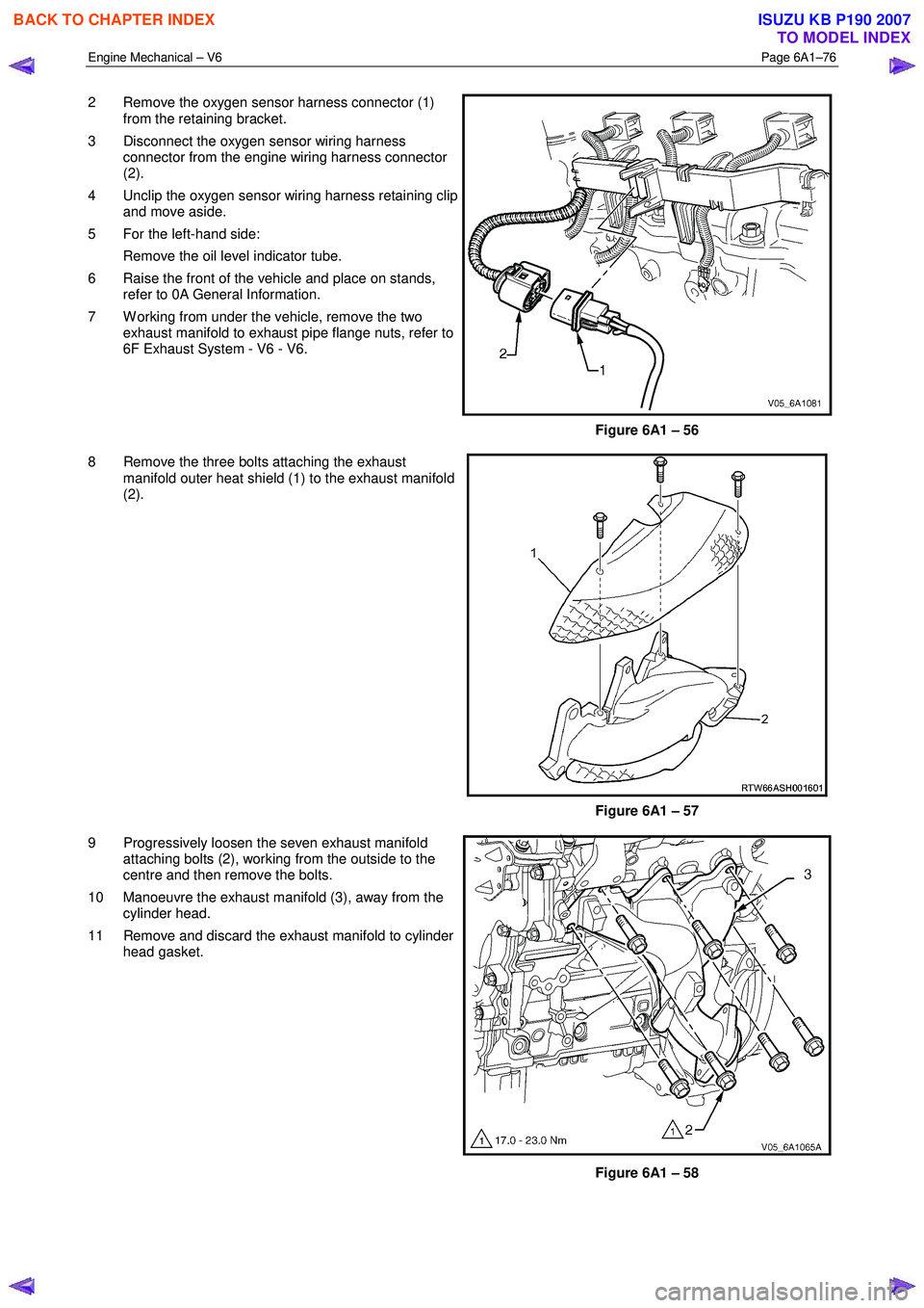
8 Remove the three bolts attaching the exhaust manifold outer heat shield (1) to the exhaust manifold
(2).
Figure 6A1 – 57
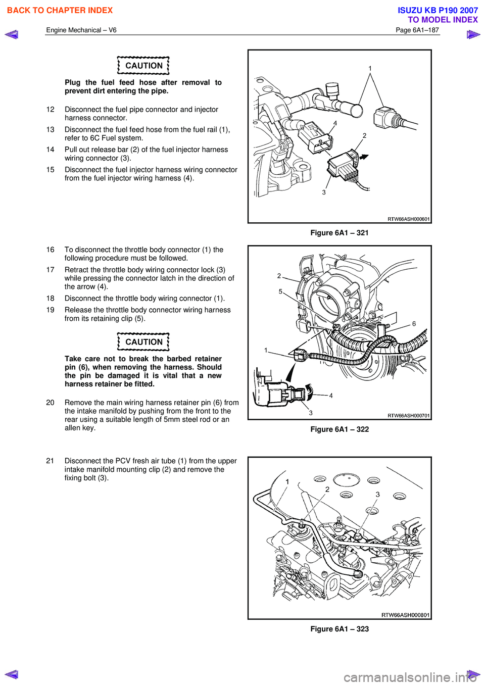
9 Progressively loosen the seven exhaust manifold attaching bolts (2), working from the outside to the
centre and then remove the bolts.
10 Manoeuvre the exhaust manifold (3), away from the cylinder head.
11 Remove and discard the exhaust manifold to cylinder head gasket.
Figure 6A1 – 58
BACK TO CHAPTER INDEX
TO MODEL INDEX
ISUZU KB P190 2007
Page 2558 of 6020
Engine Mechanical – V6 Page 6A1–79
3.12 Camshaft Cover
Remove
1 Remove the intake manifold assembly, refer to 3.10 Intake Manifold Assembly – Complete.
2 For the left-hand side, remove the evaporative (EVAP) emission canister purge solenoid, refer to 6C1-3 Engine Management – V6 – Service Operations.
3 Remove the two bolts (1) attaching the engine wiring harness former to the rear of the cylinder heads.
4 Unclip the transmission vent tube (2) from the engine wiring harness.
Figure 6A1 – 61
5 Disconnect the oxygen sensor wiring harness connector (1) from the engine wiring harness (2), left-
hand shown, right-hand similar.
Figure 6A1 – 62
BACK TO CHAPTER INDEX
TO MODEL INDEX
ISUZU KB P190 2007
Page 2559 of 6020
Engine Mechanical – V6 Page 6A1–80
6 Remove the bolt (1) attaching the ground connector
(2) to the cylinder head.
7 Fro the left-hand side, disconnect the engine coolant temperature (ECT) sensor wiring connector (3).
8 Unclip the engine wiring harness retaining lugs from the side of the camshaft cover.
Figure 6A1 – 63
9 For the right-hand side, remove the engine wiring harness retaining clip (1) from the engine control
module (ECM) bracket (2).
Figure 6A1 – 64
10 Disconnect the camshaft position (CMP) sensor wiring connector (1).
11 Unclip the engine wiring harness retaining lug (3) from the front of the camshaft cover.
12 Remove the ignition coil assemblies; refer to 6C1-3 Engine Management – V6 – Service Operations.
13 Move the engine wiring harness clear of the camshaft cover.
Figure 6A1 – 65
BACK TO CHAPTER INDEX
TO MODEL INDEX
ISUZU KB P190 2007
Page 2563 of 6020
Engine Mechanical – V6 Page 6A1–84
8 Remove Tool No. EN-46101 (1).
9 Tighten all remaining fasteners to the correct torque specification.
Engine ground connector bolt
torque specification ............................................10.0 Nm
Engine wiring harness former attaching
bolt torque specification ..........................12.0 – 16.0 Nm
Figure 6A1 – 74
3.13 Crankshaft Balancer Assembly
Remove
1 Remove the accessory drive belt, refer to 3.5 Accessory Drive Belt.
2 Remove the starter motor, refer to 6D1-2_ Starting System.
3 Install Tool No. EN-46106 (1) into the starter motor opening to stop the camshaft from rotating.
Figure 6A1 – 75
BACK TO CHAPTER INDEX
TO MODEL INDEX
ISUZU KB P190 2007
Page 2666 of 6020

Engine Mechanical – V6 Page 6A1–187
Plug the fuel feed hose after removal to
prevent dirt entering the pipe.
12 Disconnect the fuel pipe connector and injector harness connector.
13 Disconnect the fuel feed hose from the fuel rail (1), refer to 6C Fuel system.
14 Pull out release bar (2) of the fuel injector harness wiring connector (3).
15 Disconnect the fuel injector harness wiring connector from the fuel injector wiring harness (4).
Figure 6A1 – 321
16 To disconnect the throttle body connector (1) the following procedure must be followed.
17 Retract the throttle body wiring connector lock (3) while pressing the connector latch in the direction of
the arrow (4).
18 Disconnect the throttle body wiring connector (1).
19 Release the throttle body connector wiring harness from its retaining clip (5).
Take care not to break the barbed retainer
pin (6), when removing the harness. Should
the pin be damaged it is vital that a new
harness retainer be fitted.
20 Remove the main wiring harness retainer pin (6) from the intake manifold by pushing from the front to the
rear using a suitable length of 5mm steel rod or an
allen key.
Figure 6A1 – 322
21 Disconnect the PCV fresh air tube (1) from the upper intake manifold mounting clip (2) and remove the
fixing bolt (3).
Figure 6A1 – 323
BACK TO CHAPTER INDEX
TO MODEL INDEX
ISUZU KB P190 2007
Page 2668 of 6020
Engine Mechanical – V6 Page 6A1–189
28 Remove the centre exhaust pipe (1), refer to 6F
Exhaust System - V6 - V6.
Figure 6A1 – 327
29 Disconnect the two post-catalytic converter oxygen sensor wiring harness connectors, 1 each bank.
Figure 6A1 – 328
30 Disconnect the two pre-catalytic converter oxygen sensor wiring harness connectors, 1 each bank.
31 Remove the front exhaust flange nuts, three each bank.
32 Remove the front left-hand exhaust pipe from the rubber mount.
33 Remove the front exhaust pipes from the vehicle, for further information, refer to 6F Exhaust System - V6.
Figure 6A1 – 329
34 Remove the transfer case from the vehicle (4W D Only), refer to 7D Transfer Case and Adaptor Housing.
BACK TO CHAPTER INDEX
TO MODEL INDEX
ISUZU KB P190 2007
Page 2671 of 6020
Engine Mechanical – V6 Page 6A1–192
44 Remove the left-hand side engine mount (1), (automatic transmission only).
Figure 6A1 – 336
45 Unclip the oil level sensor harness from the heat shield (1).
a Remove the heat shield retaining screw (2).
b Remove the lower starter motor attaching bolt (3).
c Remove the heat shield.
d Remove the upper starter motor retaining bolt (3).
46 Remove the starter motor from the engine block and lower the starter motor as far as possible to gain
access to the wiring harness connections.
47 Remove the starter motor, (automatic transmission only).
Figure 6A1 – 337
48 Reinstall the left-hand side engine mount (1), (automatic transmission only).
49 Remove the transmission assembly, refer to 7C1 Automatic – 4L60E – General Information.
BACK TO CHAPTER INDEX
TO MODEL INDEX
ISUZU KB P190 2007