Page 4767 of 6020

7B1-48 Manual Transmission (MUX)
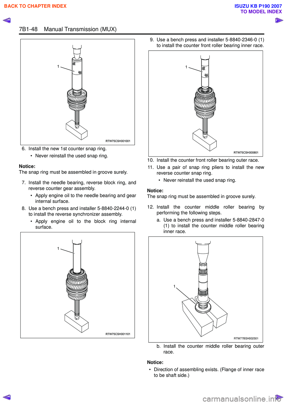
6. Install the new 1st counter snap ring.• Never reinstall the used snap ring.
Notice:
The snap ring must be assembled in groove surely.
7. Install the needle bearing, reverse block ring, and reverse counter gear assembly.
• Apply engine oil to the needle bearing and gear internal surface.
8. Use a bench press and installer 5-8840-2244-0 (1) to install the reverse synchronizer assembly.
• Apply engine oil to the block ring internal surface. 9. Use a bench press and installer 5-8840-2346-0 (1)
to install the counter front roller bearing inner race.
10. Install the counter front roller bearing outer race. 11. Use a pair of snap ring pliers to install the new reverse counter snap ring.
• Never reinstall the used snap ring.
Notice:
The snap ring must be assembled in groove surely.
12. Install the counter middle roller bearing by performing the following steps.
a. Use a bench press and installer 5-8840-2847-0 (1) to install the counter middle roller bearing
inner race.
b. Install the counter middle roller bearing outer race.
Notice: • Direction of assembling exists. (Flange of inner race to be shaft side.)
RTW75CSH001001
1
RTW75CSH001101
1
RTW75CSH000801
1
RTW77BSH002501
1
BACK TO CHAPTER INDEX
TO MODEL INDEX
ISUZU KB P190 2007
Page 4777 of 6020
7B1-58 Manual Transmission (MUX)
Special Tools
Special Tools
Illustration Tool Number/ Description5-8522-0053-0 (J-29016)Bearing Installer
5-8840-0007-0 (J-8092) Grip
5-8840-0084-0 (J-2619- 01)
Sliding Hammer
5-8840-0125-0 (J-26516) Pilot Bearing Installer
5-8840-2244-0 (J-5590) Bearing Installer
5-8840-2282-0 (J-36797) Oil Seal Installer
5852200530
5884022440
5-8840-2291-0 (J-39207)Bearing Remover
5-8840-2346-0 Installer
5-8840-2757-0 (J-45887) Bearing Remover
5-8840-2786-0 (J-46202) Oil Seal Installer
9-8522-1182-0 (J-35835) Bearing Installer
5-8840-2846-0
Oil Seal & Bearing Installer
Illustration Tool Number/ Description
5884022910
5884023460
5884027570
5884027860
9852211820
5884028460
BACK TO CHAPTER INDEX
TO MODEL INDEX
ISUZU KB P190 2007
Page 4802 of 6020

7C-24 CLUTCH
015RW 053
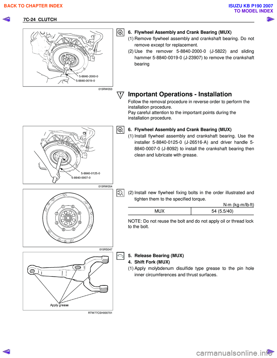
6. Flywheel Assembly and Crank Bearing (MUX)
(1) Remove flywheel assembly and crankshaft bearing. Do not remove except for replacement.
(2) Use the remover 5-8840-2000-0 (J-5822) and sliding hammer 5-8840-0019-0 (J-23907) to remove the crankshaft
bearing
Important Operations - Installation
Follow the removal procedure in reverse order to perform the
installation procedure.
Pay careful attention to the important points during the
installation procedure.
015RW 054
6. Flywheel Assembly and Crank Bearing (MUX)
(1) Install flywheel assembly and crankshaft bearing. Use the installer 5-8840-0125-0 (J-26516-A) and driver handle 5-
8840-0007-0 (J-8092) to install the crankshaft bearing then
clean and lubricate with grease.
015RS047
(2) Install new flywheel fixing bolts in the order illustrated and tighten them to the specified torque. N⋅m (kg ⋅m/lb ⋅ft)
MUX 54 (5.5/40)
NOTE: Do not reuse the bolt and do not apply oil or thread lock
to the bolt.
RTW 77CSH000701
5. Release Bearing (MUX)
4. Shift Fork (MUX)
(1)
Apply molybdenum disulfide type grease to the pin hole
inner circumferences and thrust surfaces.
BACK TO CHAPTER INDEX
TO MODEL INDEX
ISUZU KB P190 2007
Page 4807 of 6020

CLUTCH 7C-29
RTW 77CSH000301
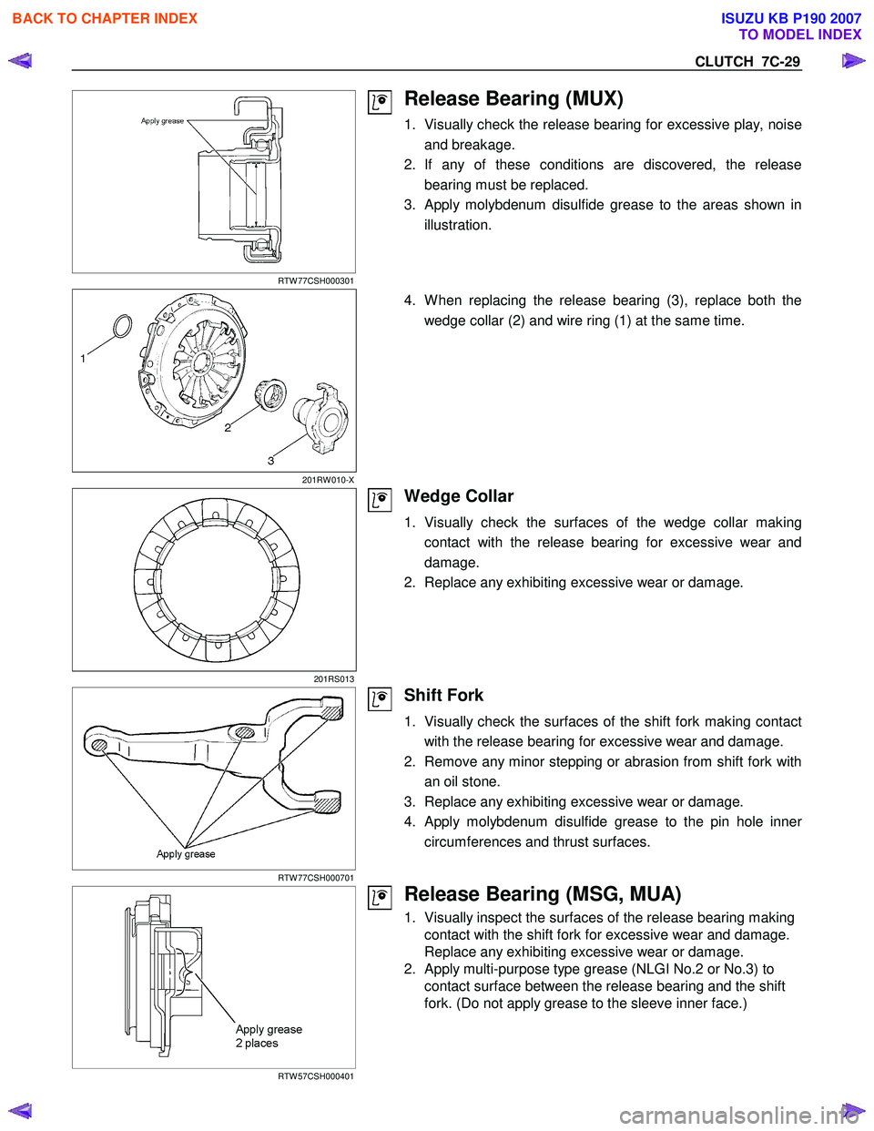
Release Bearing (MUX)
1. Visually check the release bearing for excessive play, noiseand breakage.
2. If any of these conditions are discovered, the release bearing must be replaced.
3.
Apply molybdenum disulfide grease to the areas shown in
illustration.
201RW 010-X
4. W hen replacing the release bearing (3), replace both the
wedge collar (2) and wire ring (1) at the same time.
201RS013
Wedge Collar
1. Visually check the surfaces of the wedge collar makingcontact with the release bearing for excessive wear and
damage.
2. Replace any exhibiting excessive wear or damage.
RTW 77CSH000701
Shift Fork
1. Visually check the surfaces of the shift fork making contact with the release bearing for excessive wear and damage.
2. Remove any minor stepping or abrasion from shift fork with an oil stone.
3. Replace any exhibiting excessive wear or damage.
4.
Apply molybdenum disulfide grease to the pin hole inner
circumferences and thrust surfaces.
RTW 57CSH000401
Release Bearing (MSG, MUA)
1. Visually inspect the surfaces of the release bearing making contact with the shift fork for excessive wear and damage.
Replace any exhibiting excessive wear or damage.
2. Apply multi-purpose type grease (NLGI No.2 or No.3) to contact surface between the release bearing and the shift
fork. (Do not apply grease to the sleeve inner face.)
BACK TO CHAPTER INDEX
TO MODEL INDEX
ISUZU KB P190 2007
Page 4808 of 6020

7C-30 CLUTCH
RTW 57CSH000201
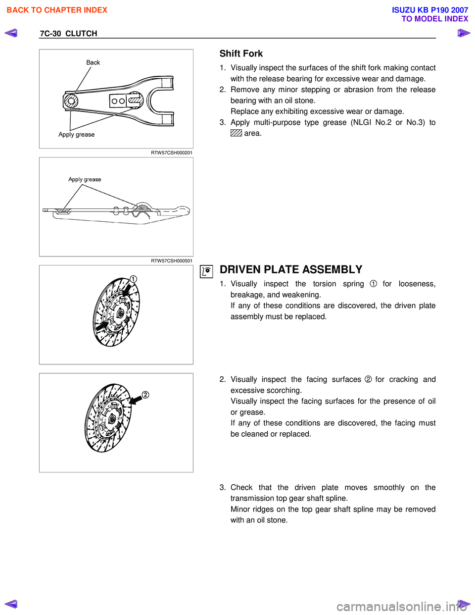
Shift Fork
1. Visually inspect the surfaces of the shift fork making contact
with the release bearing for excessive wear and damage.
2. Remove any minor stepping or abrasion from the release bearing with an oil stone.
Replace any exhibiting excessive wear or damage.
3. Apply multi-purpose type grease (NLGI No.2 or No.3) to
area.
RTW 57CSH000501
DRIVEN PLATE ASSEMBLY
1. Visually inspect the torsion spring 1 for looseness,
breakage, and weakening.
If any of these conditions are discovered, the driven plate assembly must be replaced.
2. Visually inspect the facing surfaces
2 for cracking and
excessive scorching.
Visually inspect the facing surfaces for the presence of oil or grease.
If any of these conditions are discovered, the facing must be cleaned or replaced.
3. Check that the driven plate moves smoothly on the
transmission top gear shaft spline.
Minor ridges on the top gear shaft spline may be removed with an oil stone.
BACK TO CHAPTER INDEX
TO MODEL INDEX
ISUZU KB P190 2007
Page 4810 of 6020
7C-32 CLUTCH
CLUTCH CONTROL
REMOVAL AND INSTALLATION
RTW 77CLF000601
Removal Steps
1. Pin
2. Jaw joint pin
3. Pedal assembly
4. Oil line
5. Master cylinder assembly
6. Oil line
7. Slave cylinder assembly
8. Damper cylinder assembly
Installation Steps
8. Damper cylinder assembly
7. Slave cylinder assembly
6. Oil line
5. Master cylinder assembly
4. Oil line
3. Pedal assembly
2. Jaw joint pin
1. Pin
BACK TO CHAPTER INDEX
TO MODEL INDEX
ISUZU KB P190 2007
Page 4819 of 6020
CLUTCH 7C-41
HYDRAULIC DAMPER CYLINDER
INSPECTION AND REPAIR
Make the necessary adjustments, repairs, and part replacements if excessive wear or damage is discovered during
inspection.
Visually check for oil leakage and other damage.
If oil leakage or other damage is discovered during the
inspection; the damper cylinder assembly must be replaced as
a unit.
BACK TO CHAPTER INDEX
TO MODEL INDEX
ISUZU KB P190 2007
Page 4820 of 6020
7C-42 CLUTCH
TROUBLESHOOTING
Refer to this Section to quickly diagnose and repair clutch problems.
Each troubleshooting chart has three headings arranged from left to right. (1) Checkpoint (2) Trouble Cause (3) Countermeasure
This Section is divided into five sub-sections:
1. Clutch Slippage
2. Clutch Does Not Release Properly
3. Clutch Shudder
4. Clutch Noise 1) Clutch pedal Depressed (Clutch Disengaged)
2) Clutch pedal Not Depressed (Clutch Engaged)
5. Oil Leakage
BACK TO CHAPTER INDEX
TO MODEL INDEX
ISUZU KB P190 2007