Page 4868 of 6020
7D-38 TRANSFER CASE
226R300011
36. Install the rear cover to the transfer case and tighten
the bolts to the specified torque.
Rear cover and transfer case bolt torque:
22 N ·m (2.2 kgf ·m/16 lb ·ft)
37. Apply engine oil to the companion flange O-ring.
38. Install the O-ring to the front output shaft.
39. Secure the front companion flange with a flange
holder (5-8840-0133-0).
40. Install the end nuts and tighten them to the specified
torque.
Front companion flange end nut torque:
137 N ·m (14.0 kgf ·m/101 lb ·ft)
RTW 77DSH000201
41. Use a punch (5-8840-2293-0) to caulk the front
companion flange end nut.
226R300012
RUW 34DSH000301
Legend
(1) MAX 26mm (1.02 in)
(2) MIN 4mm (0.16 in)
42.
Apply Loctite 575 to the threaded portion of the
detente plugs.
BACK TO CHAPTER INDEX
TO MODEL INDEX
ISUZU KB P190 2007
Page 4869 of 6020

TRANSFER CASE 7D-39
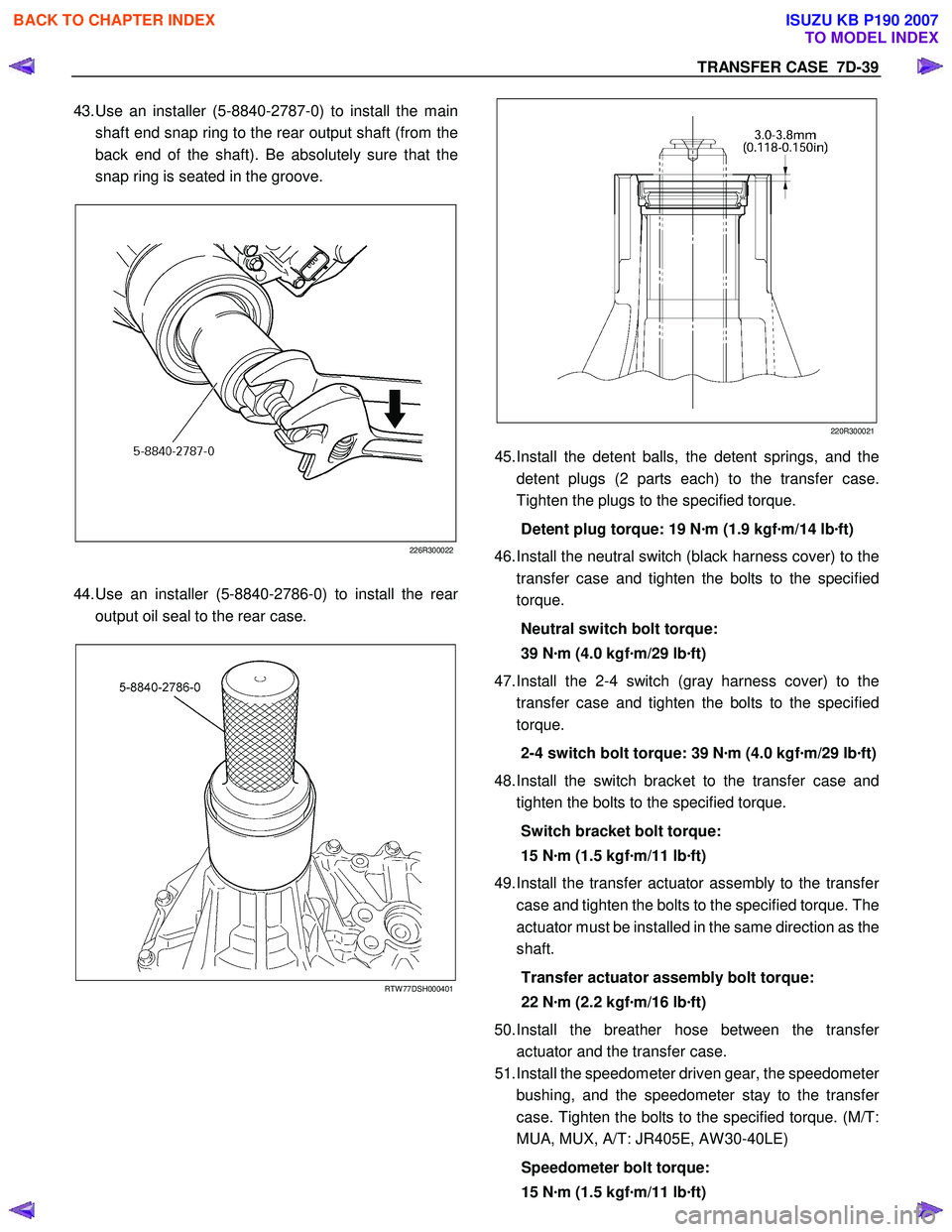
43. Use an installer (5-8840-2787-0) to install the main
shaft end snap ring to the rear output shaft (from the
back end of the shaft). Be absolutely sure that the
snap ring is seated in the groove.
226R300022
44. Use an installer (5-8840-2786-0) to install the rear
output oil seal to the rear case.
RTW 77DSH000401
220R300021
45.
Install the detent balls, the detent springs, and the
detent plugs (2 parts each) to the transfer case.
Tighten the plugs to the specified torque.
Detent plug torque: 19 N ·m (1.9 kgf ·m/14 lb ·ft)
46. Install the neutral switch (black harness cover) to the
transfer case and tighten the bolts to the specified
torque.
Neutral switch bolt torque:
39 N ·m (4.0 kgf ·m/29 lb ·ft)
47. Install the 2-4 switch (gray harness cover) to the
transfer case and tighten the bolts to the specified
torque.
2-4 switch bolt torque: 39 N ·m (4.0 kgf ·m/29 lb ·ft)
48. Install the switch bracket to the transfer case and
tighten the bolts to the specified torque.
Switch bracket bolt torque:
15 N ·m (1.5 kgf ·m/11 lb ·ft)
49. Install the transfer actuator assembly to the transfe
r
case and tighten the bolts to the specified torque. The
actuator must be installed in the same direction as the
shaft.
Transfer actuator assembly bolt torque:
22 N ·m (2.2 kgf ·m/16 lb ·ft)
50. Install the breather hose between the transfe
r
actuator and the transfer case.
51. Install the speedometer driven gear, the speedomete
r
bushing, and the speedometer stay to the transfe
r
case. Tighten the bolts to the specified torque. (M/T:
MUA, MUX, A/T: JR405E, AW 30-40LE)
Speedometer bolt torque:
15 N ·m (1.5 kgf ·m/11 lb ·ft)
BACK TO CHAPTER INDEX
TO MODEL INDEX
ISUZU KB P190 2007
Page 4870 of 6020
7D-40 TRANSFER CASE
52. Install the speed sensor to the transfer case and
tighten the specified torque. (M/T: AR-5, A/T: 4L60-E)
Speed sensor torque: 17 N ·m (1.7 kgf ·m/12 lb ·ft)
53. Install the drain plug to the transfer case and tighten it
to the specified torque.
Drain plug torque: 39 N ·m (4.0 kgf ·m/29 lb ·ft)
54. Loosen and remove the filler plug. Add the specified
volume of transfer oil (5W -30) or the equivalent to the
transfer through the filler hole.
Transfer oil volume: 1.3 lit. (1.37 US qt)
55. Replace the filler plug and tighten it to the specified
torque.
Filler plug torque: 39 N ·m (4.0 kgf ·m/29 lb ·ft)
56. Install the underguard and tighten the bolts to the
specified torque.
Underguard bolt torque:
39 N ·m (4.0 kgf ·m/29 lb ·ft)
BACK TO CHAPTER INDEX
TO MODEL INDEX
ISUZU KB P190 2007
Page 4871 of 6020
TRANSFER CASE 7D-41
Main Data and Specifications
General Specifications
Type Synchronized type gears shifting between the 2 and 4 wheel drive mode.
Planetary type gears shifting between “low" and “high".
Control method Remote control with the button switch on the instrument panel for gears
shifting among “2H", “4H" and “4L".
Gear ratio High; 1.000
Low; 2.482
Oil capacity 1.3 lit. (1.37 US qt)
Type of lubricant BESCO GEAR OIL TRANSAXLE (5W -30)
Refer to Section 0B
Torque Specifications
N⋅m (kgf ⋅m/lb ⋅ft)
RTW 67DLF000201
BACK TO CHAPTER INDEX
TO MODEL INDEX
ISUZU KB P190 2007
Page 4874 of 6020
7D-44 TRANSFER CASE
Special Tools
ILLUSTRATION PART NO.
PART NAME
ILLUSTRATION PART NO.
PART NAME
5-8840-2786-0
(J-46202)
Transfer case oil seal installer
5-8840-2784-0
(J-46200)
Ring gear installer
5-8840-0084-0
(J-2619-01)
Sliding hammer
5-8840-0133-0
(J-8614-01)
Flange holder
5-8840-0027-0
(J-26941)
Rear output shaft needle bearing replacer
5-8840-2782-0
(J-46198)
Needle bearing installer
5-8840-2293-0
(J-39209)
Punch; end nut
5-8840-2783-0
(J-46199)
Needle bearing installer
5-8840-2788-0
Front output shaft needle bearing replacer
9-8522-1268-0
Rear output shaft ball bearing installer
5-8840-2785-0
(J-46201)
Input shaft and/or front
output shaft oil seal installe
r
5-8840-2787-0
(J-46203)
Snap ring installer
BACK TO CHAPTER INDEX
TO MODEL INDEX
ISUZU KB P190 2007
Page 4920 of 6020

7D1-46 TRANSFER CONTROL SYSTEM
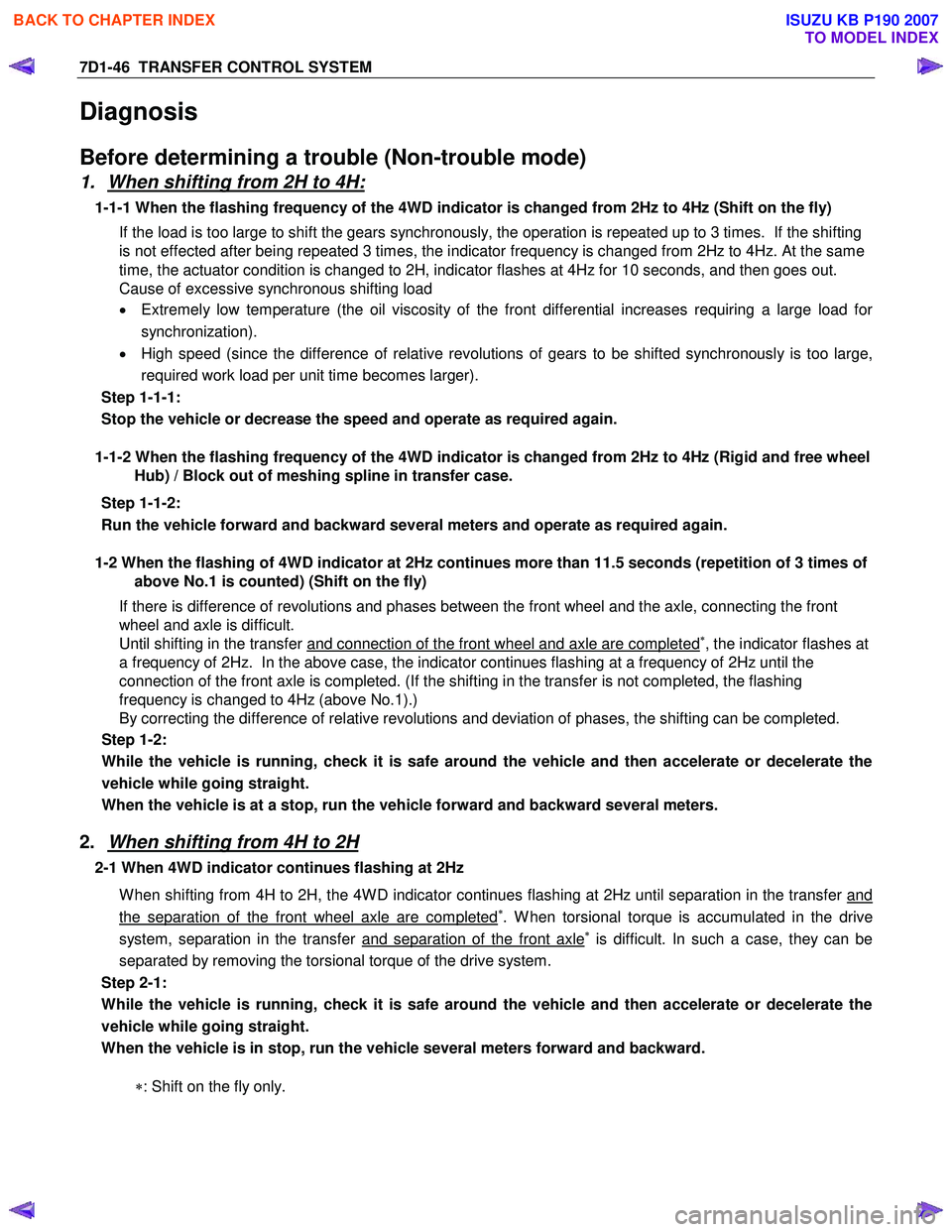
Diagnosis
Before determining a trouble (Non-trouble mode)
1. When shifting from 2H to 4H:
1-1-1 When the flashing frequency of the 4WD indicator is changed from 2Hz to 4Hz (Shift on the fly) If the load is too large to shift the gears synchronously, the operation is repeated up to 3 times. If the shifting
is not effected after being repeated 3 times, the indicator frequency is changed from 2Hz to 4Hz. At the same
time, the actuator condition is changed to 2H, indicator flashes at 4Hz for 10 seconds, and then goes out.
Cause of excessive synchronous shifting load
• Extremely low temperature (the oil viscosity of the front differential increases requiring a large load for
synchronization).
• High speed (since the difference of relative revolutions of gears to be shifted synchronously is too large,
required work load per unit time becomes larger).
Step 1-1-1:
Stop the vehicle or decrease the speed and operate as required again.
1-1-2 When the flashing frequency of the 4WD indicator is changed from 2Hz to 4Hz (Rigid and free wheel
Hub) / Block out of meshing spline in transfer case.
Step 1-1-2:
Run the vehicle forward and backward several meters and operate as required again.
1-2 When the flashing of 4WD indicator at 2Hz continues more than 11.5 seconds (repetition of 3 times of
above No.1 is counted) (Shift on the fly)
If there is difference of revolutions and phases between the front wheel and the axle, connecting the front
wheel and axle is difficult.
Until shifting in the transfer and connection of the front wheel and axle are completed
∗, the indicator flashes at
a frequency of 2Hz. In the above case, the indicator continues flashing at a frequency of 2Hz until the
connection of the front axle is completed. (If the shifting in the transfer is not completed, the flashing
frequency is changed to 4Hz (above No.1).)
By correcting the difference of relative revolutions and deviation of phases, the shifting can be completed.
Step 1-2:
While the vehicle is running, check it is safe around the vehicle and then accelerate or decelerate the
vehicle while going straight.
When the vehicle is at a stop, run the vehicle forward and backward several meters.
2. When shifting from 4H to 2H
2-1 When 4WD indicator continues flashing at 2Hz
W hen shifting from 4H to 2H, the 4W D indicator continues flashing at 2Hz until separation in the transfer and
the separation of the front wheel axle are completed∗. W hen torsional torque is accumulated in the drive
system, separation in the transfer and separation of the front axle∗ is difficult. In such a case, they can be
separated by removing the torsional torque of the drive system.
Step 2-1:
While the vehicle is running, check it is safe around the vehicle and then accelerate or decelerate the
vehicle while going straight.
When the vehicle is in stop, run the vehicle several meters forward and backward.
∗: Shift on the fly only.
BACK TO CHAPTER INDEX
TO MODEL INDEX
ISUZU KB P190 2007
Page 4954 of 6020

8A-16 ELECTRICAL-BODY AND CHASSIS
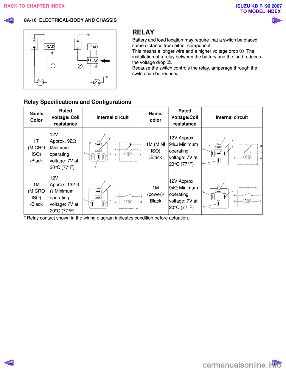
RELAY
Battery and load location may require that a switch be placed
some distance from either component.
This means a longer wire and a higher voltage drop
1. The
installation of a relay between the battery and the load reduces
the voltage drop
2.
Because the switch controls the relay, amperage through the
switch can be reduced.
Relay Specifications and Configurations
Name/ Color Rated
voltage/ Coil resistance Internal circuit
Name/
color Rated
Voltage/Coil resistance Internal circuit
1T
(MICRO ISO)
/Black 12V
Approx. 92 Ω
Minimum
operating
voltage: 7V at
20 °C (77 °F)
1M (MINI
ISO)
/Black 12V Approx.
94 Ω Minimum
operating
voltage: 7V at
20 °C (77 °F)
1M
(MICRO ISO)
/Black 12V
Approx. 132-3
Ω Minimum
operating
voltage: 7V at
20 °C (77 °F)
1M
(power)/ Black 12V Approx.
94 Ω Minimum
operating
voltage: 7V at
20 °C (77 °F)
* Relay contact shown in the wiring diagram indicates condition before actuation.
BACK TO CHAPTER INDEX TO MODEL INDEXISUZU KB P190 2007
Page 4963 of 6020

ELECTRICAL-BODY AND CHASSIS 8A-25
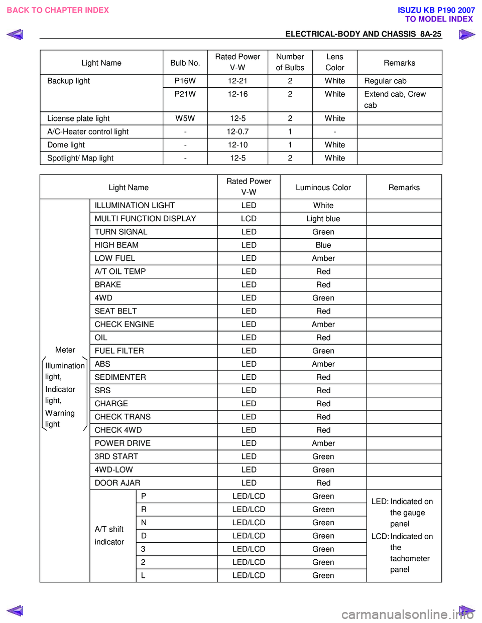
Light Name Bulb No. Rated Power
V-W Number
of Bulbs Lens
Color Remarks
P16W 12-21 2 W hite Regular cab Backup light
P21W 12-16 2 W hite Extend cab, Crew cab
License plate light W 5W 12-5 2 W hite
A/C-Heater control light - 12-0.7 1 -
Dome light - 12-10 1 W hite
Spotlight/ Map light - 12-5 2 W hite
Light Name Rated Power
V-W Luminous Color Remarks
ILLUMINATION
LIGHT LED W hite
MULTI FUNCTION DISPLAY LCD Light blue
TURN SIGNAL LED Green
HIGH BEAM LED Blue
LOW FUEL LED Amber
A/T OIL TEMP LED Red
BRAKE LED Red
4W D LED Green
SEAT BELT LED Red
CHECK ENGINE LED Amber
OIL LED Red
FUEL FILTER LED Green
ABS LED Amber
SEDIMENTER LED Red
SRS LED Red
CHARGE LED Red
CHECK TRANS LED Red
CHECK 4W D LED Red
POW ER DRIVE LED Amber
3RD START LED Green
4W D-LOW LED Green
DOOR AJAR LED Red
P LED/LCD Green
R LED/LCD Green
N LED/LCD Green
D LED/LCD Green
3 LED/LCD Green
2 LED/LCD Green
A/T shift
indicator
L LED/LCD Green LED: Indicated on
the gauge
panel
LCD: Indicated on the
tachometer
panel
Meter
Illumination
light,
Indicator
light,
W arning
light
BACK TO CHAPTER INDEX TO MODEL INDEXISUZU KB P190 2007