Page 4971 of 6020
ELECTRICAL-BODY AND CHASSIS 8A-33
FUSE LOCATION
RHD/LHD
FUSE
NO. Capacity Indication on label NO. Capacity Indication on label
C 1 10A STARTER C 1110A AUDIO
C2
C
12 20A CIGAR/ACC SOCKET
10A TRAILER *3 C 13 15A AUDIO (+B)
C3 10A ELEC IG C 14 10A METER
C4 10A TURN C 15 15A STOP
C5 10A ABS/4WD C 16
C6 10A ENGINE C 17 10A ROOM
10A ECU *4 C19 10A METER (+B)
C7 15A TCM/IG COIL/ C2 120A DOOR LOCK
10A GLOW ENGINE *4 C22
C8 10A SRS 10A ANTI THEFT *5
C9 20A FRT WIPER
C10 15A BACKUP
SLOW BLOW FUSE
NO. Capacity Indication on label
C 18 20A RR DEF
C20 30A POWER WINDOW
FUSE BOX
*3 … HFV6 (AUSTRALIA)
*4 … HFV6
*5 … 4JJ 1-TC (EUROPE)
BACK TO CHAPTER INDEX
TO MODEL INDEXISUZU KB P190 2007
Page 5290 of 6020

8A-352 ELECTRICAL-BODY AND CHASSIS
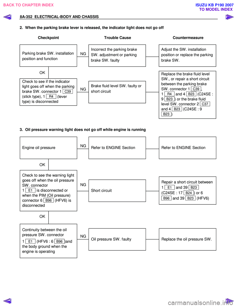
2. When the parking brake lever is released, the indicator light does not go off
Checkpoint Trouble Cause Countermeasure
Adjust the SW . installation
position or replace the parking
brake SW . Incorrect the parking brake
SW . adjustment or parking
brake SW . faulty
NG
Thermo unit malfunction
Replace the brake fluid level
SW ., or repair a short circuit
between the parking brake
SW . connector 1
C39,
1
R4 and 4 B23 (C24SE :
9
B23 ) or the brake fluid
level SW . connector 2
C37
and 4
B23 (C24SE : 9
B23 )
Check to see if the indicator
light goes off when the parking
brake SW . connector 1
C39
(stick type), 1
R4 (lever
type) is disconnected
Brake fluid level SW . faulty or
short circuit
NG
OK
Parking brake SW . installation
position and function
3. Oil pressure warning light does not go off while engine is running
Refer to ENGINE Section
Refer to ENGINE Section
NG Thermo unit malfunction
Check to see the warning light
goes off when the oil pressure
SW . connector
1
E1 is disconnected or
when the PIM (Oil pressure)
connector 6
B96 (HFV6) is
disconnected
Repair a short circuit between
1
E1 and 39 B23
(C24SE : 17
B24) or 6
B96 and 39 B23 (HFV6)
Short circuit
NG
OK
Replace the oil pressure SW .
Continuity between the oil
pressure SW . connector
1
E1 (HFV6 : 6 B96 )and
the body ground when the
engine is operating
Oil pressure SW . faulty
NG
OK
Engine oil pressure
BACK TO CHAPTER INDEX TO MODEL INDEXISUZU KB P190 2007
Page 5303 of 6020

ELECTRICAL-BODY AND CHASSIS 8A-365
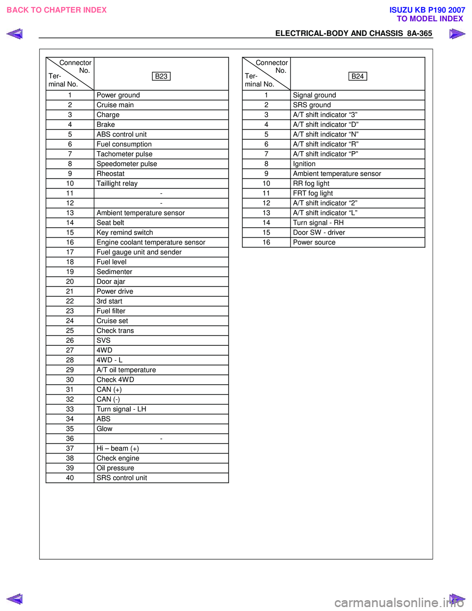
Connector
Ter- No.
minal No.
B23
1 Power ground
2 Cruise main
3 Charge
4 Brake
5 ABS control unit
6 Fuel consumption
7 Tachometer pulse
8 Speedometer pulse
9 Rheostat
10 Taillight relay
11 -
12 -
13 Ambient temperature sensor
14 Seat belt
15 Key remind switch
16 Engine coolant temperature sensor
17 Fuel gauge unit and sender
18 Fuel level
19 Sedimenter
20 Door ajar
21 Power drive
22 3rd start
23 Fuel filter
24 Cruise set
25 Check trans
26 SVS
27 4W D
28 4W D - L
29 A/T oil temperature
30 Check 4W D
31 CAN (+)
32 CAN (-)
33 Turn signal - LH
34 ABS
35 Glow
36 -
37 Hi – beam (+)
38 Check engine
39 Oil pressure
40 SRS control unit
Connector
Ter- No.
minal No.
B24
1 Signal ground
2 SRS ground
3 A/T shift indicator “3”
4 A/T shift indicator “D”
5 A/T shift indicator “N”
6 A/T shift indicator “R”
7 A/T shift indicator “P”
8 Ignition
9 Ambient temperature sensor
10 RR fog light
11 FRT fog light
12 A/T shift indicator “2”
13 A/T shift indicator “L”
14 Turn signal - RH
15 Door SW - driver
16 Power source
BACK TO CHAPTER INDEX TO MODEL INDEXISUZU KB P190 2007
Page 5304 of 6020

8A-366 ELECTRICAL-BODY AND CHASSIS
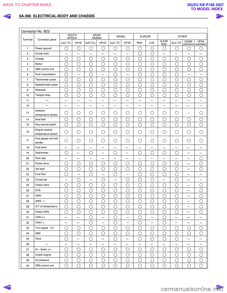
Connector No. B23 SOUTH
AFRICA SAUDI
ARABIA ISRAEL EUROPE OTHER
Terminal Connector place
4JJ1-TC HFV6 4JA1T(L) HFV6 4JJ1-TC HFV6 RHD LHD G.EXP
RHD 4JJ1-TC
C24SE
AUSTRALIAHFV6AUSTRALIA
1
Power ground
2 Cruise main
―
― ― ― ― ― ― ― ― ―
3
Charge
4 Brake
5 ABS control unit
6 Fuel consumption ―
―
―
―
―
7 Tachometer pulse
8 Speedometer pulse
9 Rheostat
10 Taillight relay
11 ―
― ― ― ― ― ― ― ― ― ― ― ―
12 ―
― ― ― ― ― ― ― ― ― ― ― ―
13 Ambient
temperature sensor ―
14 Seat belt
15 Key remind switch
16 Engine coolant
temperature sensor
17 Fuel gauge unit and
sender
18 Fuel level
― ― ― ― ― ― ― ― ― ― ― ―
19 Sedimenter ―
―
―
―
―
20 Door ajar
― ― ― ― ― ― ― ― ― ― ―
21 Power drive ―
22 3rd start ―
23 Fuel filter ―
―
―
―
―
24 Cruise set
― ―
―
―
―
―
25 Check trans ―
26 SVS ―
27 4W D ―
28 4W D - L ―
29 A/T oil temperature ―
30 Check 4W D ―
31 CAN (+)
― ― ―
―
―
― ― ―
32
CAN (-)
― ― ―
―
―
― ― ―
33
Turn signal - LH
34 ABS
35 Glow ―
―
―
―
―
36 ―
― ― ― ― ― ― ― ― ― ― ― ―
37 Hi – beam (+)
38 Check engine
39 Oil pressure
40 SRS control unit
BACK TO CHAPTER INDEX
TO MODEL INDEXISUZU KB P190 2007
Page 5427 of 6020

ELECTRICAL-BODY AND CHASSIS 8A-489
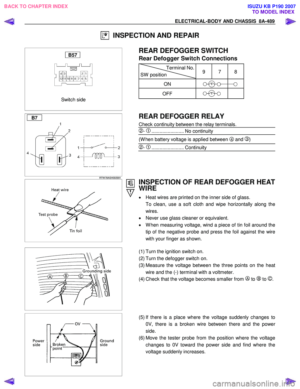
INSPECTION AND REPAIR
Switch side
B57
REAR DEFOGGER SWITCH
Rear Defogger Switch Connections
Terminal No.
SW position 9 7 8
ON
OFF
B7
RTW 78ASH002901
REAR DEFOGGER RELAY
Check continuity between the relay terminals.
2- 1........................ No continuity
(W hen battery voltage is applied between 4 and 3)
2- 1........................ Continuity
INSPECTION OF REAR DEFOGGER HEAT
WIRE
• Heat wires are printed on the inner side of glass.
To clean, use a soft cloth and wipe horizontally along the wires.
• Never use glass cleaner or equivalent.
• W hen measuring voltage, wind a piece of tin foil around the
tip of the negative probe and press the foil against the wire
with your finger as shown.
(1) Turn the ignition switch on.
(2) Turn the defogger switch on.
(3) Measure the voltage between the three points on the heat wire and the (-) terminal with a voltmeter.
(4) Check that the voltage becomes smaller from
A to B to C.
(5) If there is a place where the voltage suddenly changes to
0V, there is a broken wire between there and the powe
r
side.
(6) Move the tester probe from the position where the voltage changes to 0V toward the power side and find where the
voltage suddenly increases.
BACK TO CHAPTER INDEX TO MODEL INDEXISUZU KB P190 2007
Page 5547 of 6020
ELECTRICAL-BODY AND CHASSIS 8A-609
No. Connector face No. Connector face
B74
NOT USED B85
W eld splice 7 (Ground)
B75
Black
Rear fog light C/U B86
W eld splice 8 (Ground)
B76
White
Front rear fog light switch B87
NOT USED
B77
White
Immobilizer C/U B88
W eld splice 5 (Ground)
B78
White
Key cylinder antenna coil B89
~
B94 NOT USED
B79
White
Short connector (cooler only) B95
White
Keyless entry control unit
B80
Black
Hazard relay (RH) B96
Gray PIM1
B81
Black
Hazard relay (LH) B97
WhitePIM2
B82
W eld splice 6 (Ground) B98
WhiteDoor lock C/U
B83
~
B84 NOT USED B101
White
Key inter lock
BACK TO CHAPTER INDEX TO MODEL INDEXISUZU KB P190 2007
Page 5557 of 6020
ELECTRICAL-BODY AND CHASSIS 8A-619
No. Connector face No. Connector face
E1
Gray
Oil pressure switch E9
Gray
T.D.C sensor
E2
(C24SE)
Magnetic clutch E10
SilverEngine ground
E3
Black
Magnetic clutch AC COMP E11
Natural greenNeutral switch
E4
Green
Generator E12
Natural greenNeutral switch
E5
TPS EGR E13
Gray Injector nozzle 1
E6
(C24SE)
Fuel injector (C24SE) E14
Gray
Injector nozzle 2
E6
Injector pump E15
Gray Injector nozzle 3
E7
(C24SE)
Fuel injector (C24SE) E16
Gray
Injector nozzle 4
E8
(C24SE)
Fuel injector (C24SE) E17
Silver
Generator (B)
E9
(C24SE)
Fuel injector (C24SE) E18
(C24SE)
Ignition coil
BACK TO CHAPTER INDEX TO MODEL INDEXISUZU KB P190 2007
Page 5559 of 6020
ELECTRICAL-BODY AND CHASSIS 8A-621
No. Connector face No. Connector face
E44
Black
Vehicle speed sensor E53
NOT USED
E45
Gray
2W D-4W D switch E54
A/T term ASM (AW 30-40LE)
E46
Brown
H-L neutral switch E54
BlackA/T term ASM (JR405E)
E47
Black
MAF & IAT sensor E55
~
E58 NOT USED
E48
Black
Fuel rail pressure sensor E59
(C24SE)
Crank position sensor (C24SE)
E49
Silver
Glow plug E60
(C24SE)
ECM
E50
Gray
Suction control valve (SVC) E61
~
E63 NOT USED
E51
Gray
Inhibiter switch (AW 30-40LE) E64
(C24SE)
Oil pressure switch (P/STRG)
E51
Black
Inhibitor switch (JR405E) E65
(C24SE)
Thermo unit
E52
Black
Crankshaft position (CKP) sensor E66
(C24SE)
Duty solenoid
BACK TO CHAPTER INDEX TO MODEL INDEXISUZU KB P190 2007