Page 4718 of 6020
7B1-112 MANUAL TRANSMISSION
Special Tools (4×
××
×
4)
ILLUSTRATION TOOL NO.
TOOL NAME ILLUSTRATION
TOOL NO.
TOOL NAME
5-8840-2158-0
(J-37222)
Mainshaft retainer remover 5-8840-2159-0
(J-37223)
Mainshaft end bearing installer
5-8840-2027-0
Puller 5-8840-0015-0
(J-22912-01) Bearing
remover/installer
5-8840-2160-0
(J-37224)
Holding fixture
5-8522-0050-0
(J-29769)
Rear case oil seal installer
5-8840-0003-0
(J-3289-20)
Holding fixture base 5-8840-0026-0
(J-26540)
Front cover oil seal installer
5-8840-2156-0
(J-37219)
Mainshaft nut wrench 9-8522-1165-0
(J-6133-01)
Mainshaft collar remover
5-8840-0047-0
(J-37225)
Tork bit wrench
(T– 45) 5-8840-0007-0
(J-8092) Grip
BACK TO CHAPTER INDEX
TO MODEL INDEX
ISUZU KB P190 2007
Page 4724 of 6020
Manual Transmission (MUX) 7B1-5
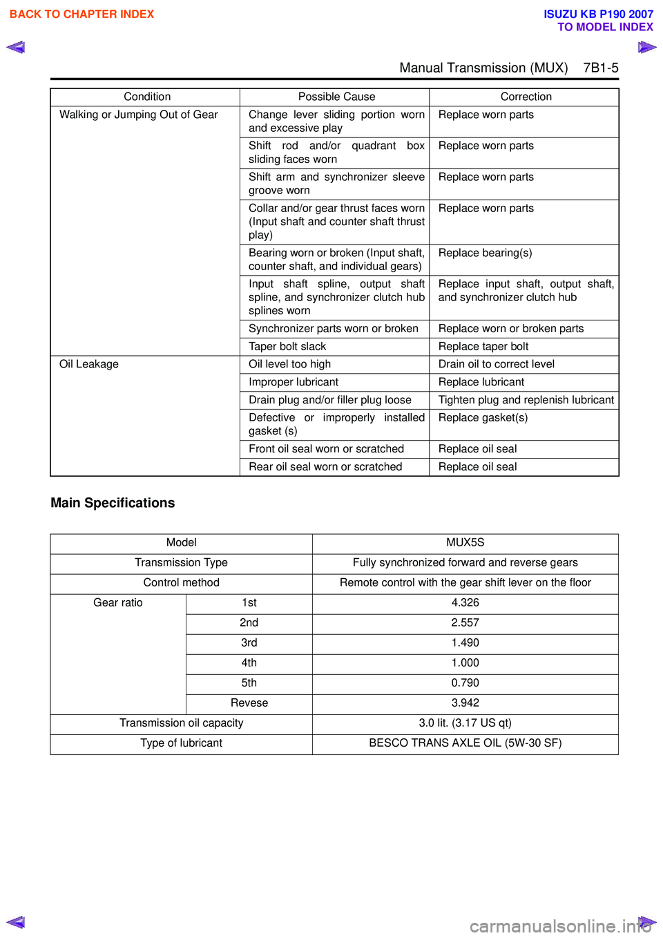
Main Specifications
Walking or Jumping Out of Gear Change lever sliding portion wornand excessive playReplace worn parts
Shift rod and/or quadrant box
sliding faces worn Replace worn parts
Shift arm and synchronizer sleeve
groove worn Replace worn parts
Collar and/or gear thrust faces worn
(Input shaft and counter shaft thrust
play) Replace worn parts
Bearing worn or broken (Input shaft,
counter shaft, and individual gears) Replace bearing(s)
Input shaft spline, output shaft
spline, and synchronizer clutch hub
splines worn Replace input shaft, output shaft,
and synchronizer clutch hub
Synchronizer parts worn or broken Replace worn or broken parts
Taper bolt slack Replace taper bolt
Oil Leakage Oil level too high Drain oil to correct level Improper lubricant Replace lubricant
Drain plug and/or filler plug loose Tighten plug and replenish lubricant
Defective or improperly installed
gasket (s) Replace gasket(s)
Front oil seal worn or scratched Replace oil seal
Rear oil seal worn or scratched Replace oil seal
Model MUX5S
Transmission Type Fully synchronized forward and reverse gears
Control method Remote control with the gear shift lever on the floor
Gear ratio 1st 4.326
2nd 2.557
3rd 1.490
4th 1.000
5th 0.790
Revese 3.942
Transmission oil capacity 3.0 lit. (3.17 US qt)
Type of lubricant BESCO TRANS AXLE OIL (5W-30 SF)
Condition
Possible Cause Correction
BACK TO CHAPTER INDEX
TO MODEL INDEX
ISUZU KB P190 2007
Page 4737 of 6020
7B1-18 Manual Transmission (MUX)
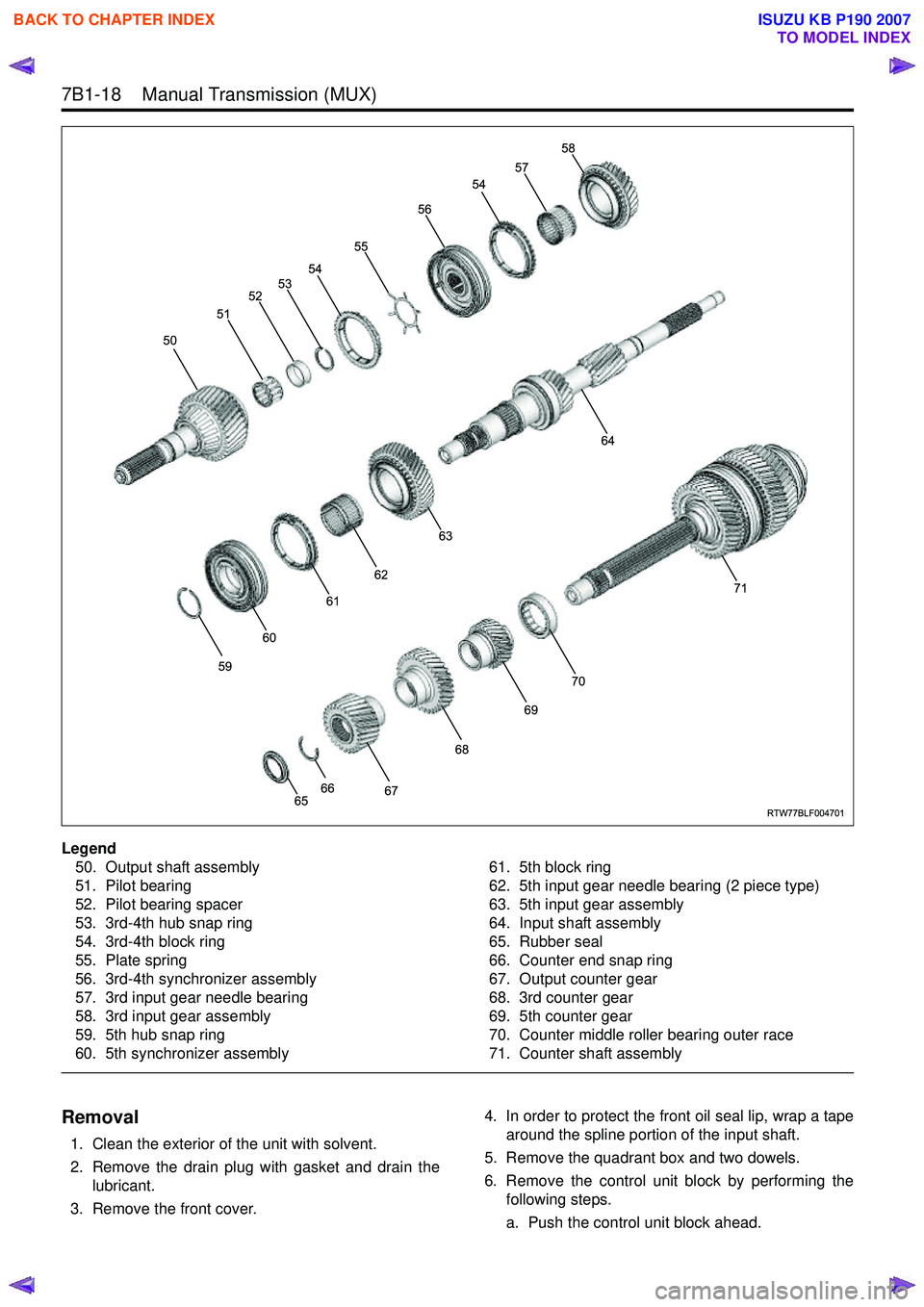
Legend50. Output shaft assembly
51. Pilot bearing
52. Pilot bearing spacer
53. 3rd-4th hub snap ring
54. 3rd-4th block ring
55. Plate spring
56. 3rd-4th synchronizer assembly
57. 3rd input gear needle bearing
58. 3rd input gear assembly
59. 5th hub snap ring
60. 5th synchronizer assembly 61. 5th block ring
62. 5th input gear needle bearing (2 piece type)
63. 5th input gear assembly
64. Input shaft assembly
65. Rubber seal
66. Counter end snap ring
67. Output counter gear
68. 3rd counter gear
69. 5th counter gear
70. Counter middle roller bearing outer race
71. Counter shaft assembly
Removal
1. Clean the exterior of the unit with solvent.
2. Remove the drain plug with gasket and drain the lubricant.
3. Remove the front cover. 4. In order to protect the front oil seal lip, wrap a tape
around the spline portion of the input shaft.
5. Remove the quadrant box and two dowels.
6. Remove the control unit block by performing the following steps.
a. Push the control unit block ahead.
RTW77BLF004701
50 51
52
53 54 55 56
54
57 58
64
63
62
61
60
59
6566
67 68
69
70 71
BACK TO CHAPTER INDEX
TO MODEL INDEX
ISUZU KB P190 2007
Page 4743 of 6020
7B1-24 Manual Transmission (MUX)
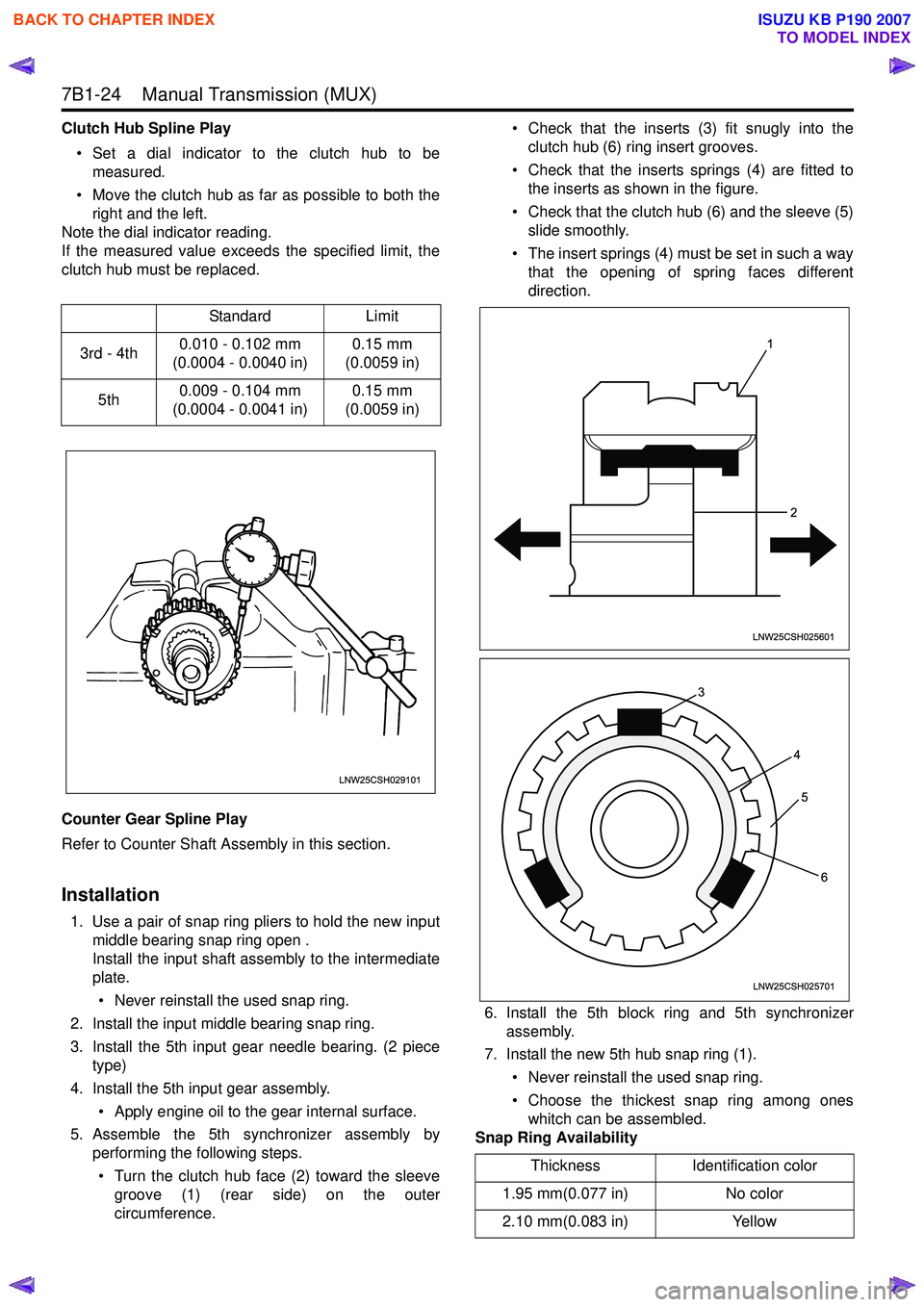
Clutch Hub Spline Play• Set a dial indicator to the clutch hub to be measured.
• Move the clutch hub as far as possible to both the right and the left.
Note the dial indicator reading.
If the measured value exceeds the specified limit, the
clutch hub must be replaced.
Counter Gear Spline Play
Refer to Counter Shaft Assembly in this section.
Installation
1. Use a pair of snap ring pliers to hold the new input middle bearing snap ring open .
Install the input shaft assembly to the intermediate
plate.
• Never reinstall the used snap ring.
2. Install the input middle bearing snap ring.
3. Install the 5th input gear needle bearing. (2 piece type)
4. Install the 5th input gear assembly. • Apply engine oil to the gear internal surface.
5. Assemble the 5th synchronizer assembly by performing the following steps.
• Turn the clutch hub face (2) toward the sleeve groove (1) (rear side) on the outer
circumference. • Check that the inserts (3) fit snugly into the
clutch hub (6) ring insert grooves.
• Check that the inserts springs (4) are fitted to the inserts as shown in the figure.
• Check that the clutch hub (6) and the sleeve (5) slide smoothly.
• The insert springs (4) must be set in such a way that the opening of spring faces different
direction.
6. Install the 5th block ring and 5th synchronizer assembly.
7. Install the new 5th hub snap ring (1).
• Never reinstall the used snap ring.
• Choose the thickest snap ring among ones whitch can be assembled.
Snap Ring Availability
Standard
Limit
3rd - 4th 0.010 - 0.102 mm
(0.0004 - 0.0040 in) 0.15 mm
(0.0059 in)
5th 0.009 - 0.104 mm
(0.0004 - 0.0041 in) 0.15 mm
(0.0059 in)
LNW25CSH029101
Thickness Identification color
1.95 mm(0.077 in) No color
2.10 mm(0.083 in) Yellow
1
2
LNW25CSH025601
3 45
6
LNW25CSH025701
BACK TO CHAPTER INDEX
TO MODEL INDEX
ISUZU KB P190 2007
Page 4744 of 6020
Manual Transmission (MUX) 7B1-25
8. Install the counter middle roller bearing outer race,counter shaft assembly and 5th counter gear to the
intermediate plate.
• Apply engine oil to the gear internal surface.
9. Install the 3rd counter gear. • Apply engine oil to the gear internal surface.
10. Iinstall the 3rd input gear needle bearing.
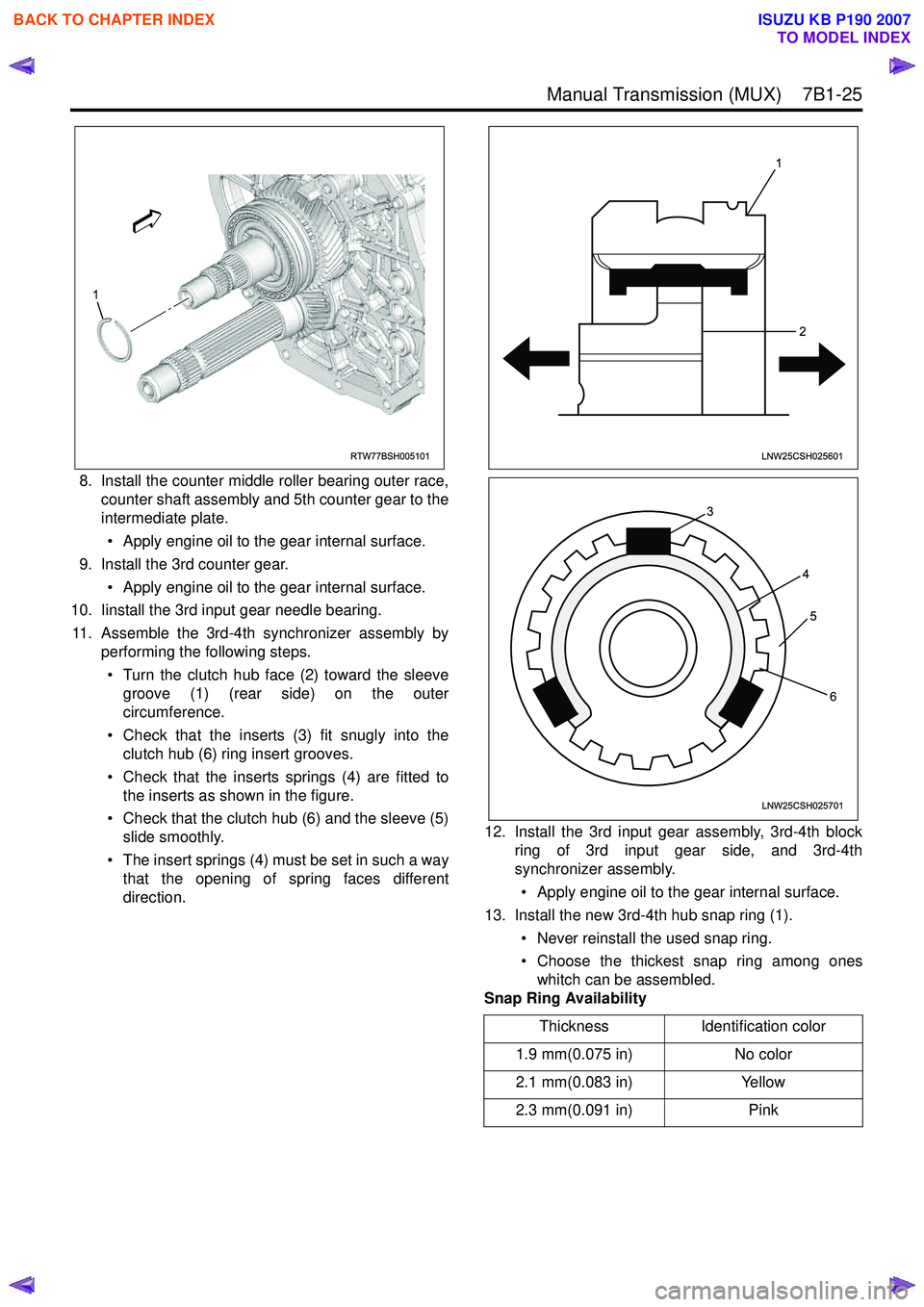
11. Assemble the 3rd-4th synchronizer assembly by performing the following steps.
• Turn the clutch hub face (2) toward the sleeve groove (1) (rear side) on the outer
circumference.
• Check that the inserts (3) fit snugly into the clutch hub (6) ring insert grooves.
• Check that the inserts springs (4) are fitted to the inserts as shown in the figure.
• Check that the clutch hub (6) and the sleeve (5) slide smoothly.
• The insert springs (4) must be set in such a way that the opening of spring faces different
direction. 12. Install the 3rd input gear assembly, 3rd-4th block
ring of 3rd input gear side, and 3rd-4th
synchronizer assembly.
• Apply engine oil to the gear internal surface.
13. Install the new 3rd-4th hub snap ring (1).
• Never reinstall the used snap ring.
• Choose the thickest snap ring among ones whitch can be assembled.
Snap Ring Availability
RTW77BSH005101
1
Thickness Identification color
1.9 mm(0.075 in) No color
2.1 mm(0.083 in) Yellow
2.3 mm(0.091 in) Pink
1
2
LNW25CSH025601
3 45
6
LNW25CSH025701
BACK TO CHAPTER INDEX
TO MODEL INDEX
ISUZU KB P190 2007
Page 4745 of 6020
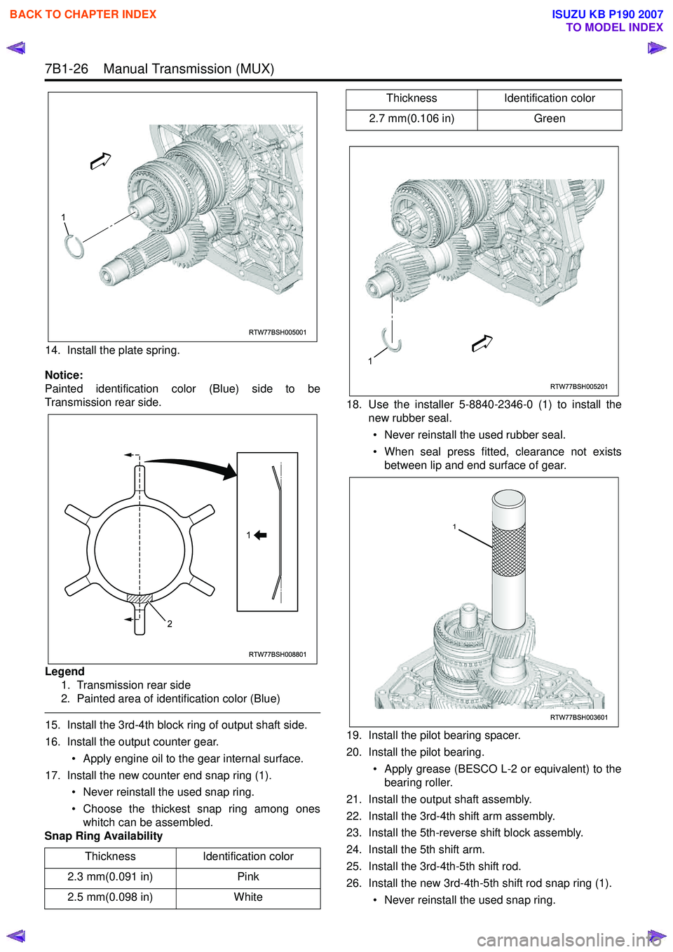
7B1-26 Manual Transmission (MUX)
14. Install the plate spring.
Notice:
Painted identification color (Blue) side to be
Transmission rear side.
Legend 1. Transmission rear side
2. Painted area of identification color (Blue)
15. Install the 3rd-4th block ring of output shaft side.
16. Install the output counter gear.
• Apply engine oil to the gear internal surface.
17. Install the new counter end snap ring (1). • Never reinstall the used snap ring.
• Choose the thickest snap ring among ones whitch can be assembled.
Snap Ring Availability 18. Use the installer 5-8840-2346-0 (1) to install the
new rubber seal.
• Never reinstall the used rubber seal.
• When seal press fitted, clearance not exists between lip and end surface of gear.
19. Install the pilot bearing spacer.
20. Install the pilot bearing. • Apply grease (BESCO L-2 or equivalent) to thebearing roller.
21. Install the output shaft assembly.
22. Install the 3rd-4th shift arm assembly.
23. Install the 5th-reverse shift block assembly.
24. Install the 5th shift arm.
25. Install the 3rd-4th-5th shift rod.
26. Install the new 3rd-4th-5th shift rod snap ring (1).
• Never reinstall the used snap ring.
Thickness
Identification color
2.3 mm(0.091 in) Pink
2.5 mm(0.098 in) White
RTW77BSH005001
1
RTW77BSH008801
1
2
2.7 mm(0.106 in) Green
Thickness
Identification color
RTW77BSH005201
1
RTW77BSH003601
1
BACK TO CHAPTER INDEX
TO MODEL INDEX
ISUZU KB P190 2007
Page 4748 of 6020
Manual Transmission (MUX) 7B1-29
42. In order to protect the front oil seal lip, wrap a tapearound the spline portion of the input shaft.
43. Install the intermediate plate assembly with gear (1) to the front case.
• Apply recommended liquid gasket (LOCTITE FMD-127 or equivalent) with the width of 3 to 5
mm to the area marked in the figure below. 44. Install the magnet (1).
45. Remove the straight plug (1) from the rear case.
46. Install the rear case assembly.
RTW77BSH007601
1
4
3
2
RTW77BSH005801
RTW77BSH007501
1
RTW77BSH008201
1
RTW77BSH0063011
BACK TO CHAPTER INDEX
TO MODEL INDEX
ISUZU KB P190 2007
Page 4752 of 6020
Manual Transmission (MUX) 7B1-33
63. Install the front cover.• Tighten the front cover bolts to the specifiedtorque.
Torque: 23 N ⋅m (2.3 kgf ⋅m/17 lb ⋅ft)
64. After reassembling the transmission, refill the case with the new specified transmission oil.
a. Install the drain plug with new gasket. • Never reinstall the used gasket.
• Apply engine oil to the new gasket surface.
• Tighten the drain plug to the specified torque.
Torque: 39 N ⋅m (4.0 kgf ⋅m/29 lb ⋅ft)
b. Remove the filler plug with gasket.
c. Refill the case with the new specified transmission oil (BESCO Trans Axle Oil 5W-30
SF) amount 3.0 liters.
d. Install the filler plug with new gasket. • Never reinstall the used gasket.
• Apply engine oil to the new gasket surface.
• Tighten the filler plug to the specified torque.
Torque: 39 N ⋅m (4.0 kgf ⋅m/29 lb ⋅ft)
BACK TO CHAPTER INDEX
TO MODEL INDEX
ISUZU KB P190 2007